EP1522801A1 - Latentwärmeabsorber für Gaskessel - Google Patents
Latentwärmeabsorber für Gaskessel Download PDFInfo
- Publication number
- EP1522801A1 EP1522801A1 EP04356054A EP04356054A EP1522801A1 EP 1522801 A1 EP1522801 A1 EP 1522801A1 EP 04356054 A EP04356054 A EP 04356054A EP 04356054 A EP04356054 A EP 04356054A EP 1522801 A1 EP1522801 A1 EP 1522801A1
- Authority
- EP
- European Patent Office
- Prior art keywords
- chamber
- heat exchanger
- gas boiler
- latent heat
- duct
- Prior art date
- Legal status (The legal status is an assumption and is not a legal conclusion. Google has not performed a legal analysis and makes no representation as to the accuracy of the status listed.)
- Withdrawn
Links
Images


Classifications
-
- F—MECHANICAL ENGINEERING; LIGHTING; HEATING; WEAPONS; BLASTING
- F24—HEATING; RANGES; VENTILATING
- F24H—FLUID HEATERS, e.g. WATER OR AIR HEATERS, HAVING HEAT-GENERATING MEANS, e.g. HEAT PUMPS, IN GENERAL
- F24H1/00—Water heaters, e.g. boilers, continuous-flow heaters or water-storage heaters
- F24H1/22—Water heaters other than continuous-flow or water-storage heaters, e.g. water heaters for central heating
- F24H1/40—Water heaters other than continuous-flow or water-storage heaters, e.g. water heaters for central heating with water tube or tubes
-
- F—MECHANICAL ENGINEERING; LIGHTING; HEATING; WEAPONS; BLASTING
- F24—HEATING; RANGES; VENTILATING
- F24H—FLUID HEATERS, e.g. WATER OR AIR HEATERS, HAVING HEAT-GENERATING MEANS, e.g. HEAT PUMPS, IN GENERAL
- F24H1/00—Water heaters, e.g. boilers, continuous-flow heaters or water-storage heaters
- F24H1/10—Continuous-flow heaters, i.e. heaters in which heat is generated only while the water is flowing, e.g. with direct contact of the water with the heating medium
- F24H1/12—Continuous-flow heaters, i.e. heaters in which heat is generated only while the water is flowing, e.g. with direct contact of the water with the heating medium in which the water is kept separate from the heating medium
- F24H1/14—Continuous-flow heaters, i.e. heaters in which heat is generated only while the water is flowing, e.g. with direct contact of the water with the heating medium in which the water is kept separate from the heating medium by tubes, e.g. bent in serpentine form
-
- F—MECHANICAL ENGINEERING; LIGHTING; HEATING; WEAPONS; BLASTING
- F24—HEATING; RANGES; VENTILATING
- F24H—FLUID HEATERS, e.g. WATER OR AIR HEATERS, HAVING HEAT-GENERATING MEANS, e.g. HEAT PUMPS, IN GENERAL
- F24H8/00—Fluid heaters characterised by means for extracting latent heat from flue gases by means of condensation
-
- F—MECHANICAL ENGINEERING; LIGHTING; HEATING; WEAPONS; BLASTING
- F24—HEATING; RANGES; VENTILATING
- F24H—FLUID HEATERS, e.g. WATER OR AIR HEATERS, HAVING HEAT-GENERATING MEANS, e.g. HEAT PUMPS, IN GENERAL
- F24H8/00—Fluid heaters characterised by means for extracting latent heat from flue gases by means of condensation
- F24H8/006—Means for removing condensate from the heater
-
- F—MECHANICAL ENGINEERING; LIGHTING; HEATING; WEAPONS; BLASTING
- F28—HEAT EXCHANGE IN GENERAL
- F28F—DETAILS OF HEAT-EXCHANGE AND HEAT-TRANSFER APPARATUS, OF GENERAL APPLICATION
- F28F1/00—Tubular elements; Assemblies of tubular elements
- F28F1/02—Tubular elements of cross-section which is non-circular
-
- F—MECHANICAL ENGINEERING; LIGHTING; HEATING; WEAPONS; BLASTING
- F28—HEAT EXCHANGE IN GENERAL
- F28F—DETAILS OF HEAT-EXCHANGE AND HEAT-TRANSFER APPARATUS, OF GENERAL APPLICATION
- F28F1/00—Tubular elements; Assemblies of tubular elements
- F28F1/10—Tubular elements and assemblies thereof with means for increasing heat-transfer area, e.g. with fins, with projections, with recesses
- F28F1/12—Tubular elements and assemblies thereof with means for increasing heat-transfer area, e.g. with fins, with projections, with recesses the means being only outside the tubular element
- F28F1/24—Tubular elements and assemblies thereof with means for increasing heat-transfer area, e.g. with fins, with projections, with recesses the means being only outside the tubular element and extending transversely
- F28F1/26—Tubular elements and assemblies thereof with means for increasing heat-transfer area, e.g. with fins, with projections, with recesses the means being only outside the tubular element and extending transversely the means being integral with the element
-
- Y—GENERAL TAGGING OF NEW TECHNOLOGICAL DEVELOPMENTS; GENERAL TAGGING OF CROSS-SECTIONAL TECHNOLOGIES SPANNING OVER SEVERAL SECTIONS OF THE IPC; TECHNICAL SUBJECTS COVERED BY FORMER USPC CROSS-REFERENCE ART COLLECTIONS [XRACs] AND DIGESTS
- Y02—TECHNOLOGIES OR APPLICATIONS FOR MITIGATION OR ADAPTATION AGAINST CLIMATE CHANGE
- Y02B—CLIMATE CHANGE MITIGATION TECHNOLOGIES RELATED TO BUILDINGS, e.g. HOUSING, HOUSE APPLIANCES OR RELATED END-USER APPLICATIONS
- Y02B30/00—Energy efficient heating, ventilation or air conditioning [HVAC]
Definitions
- the present invention relates to a gas boiler employing an upward-type Bunsen burner combustion system, and more particularly to a latent heat absorbing apparatus for a gas boiler, which recovers waste heat, generally being produced after heat exchange with heating water through a sensible heat exchanger and then discharged along with exhaust gas, through a latent heat exchanger, so that thermal efficiency is enhanced, resulting in a reduction of gas consumption.
- a gas boiler is constructed such that heat of exhaust gas produced after burning fuels, such as gas, is exchanged with the heat of water, such as heating water, in a heat exchanger disposed on a combustion chamber, thereby heating rooms or water.
- the combustion gas is supplied to carry out heat exchange through the heat exchanger, and is then discharged out of the gas boiler as exhaust gas.
- the exhaust gas has a temperature of lower than the initial temperature of the combustion gas but higher than the room's temperature.
- a method for recycling the latent heat of the exhaust gas there was suggested a method of utilizing a dual-heat exchange system using both the combustion gas and the exhausted gas.
- the dual-heat exchange operation is accomplished by exchanging the heat of the initial combustion gas through the sensible heat exchanger and then exchanging the heat of the exhaust gas, produced after the above heat exchange, through the latent heat exchanger disposed on the sensible heat exchanger.
- the present invention has been made to solve the above problems, and it is an object of the present invention to provide a latent heat absorbing apparatus for a gas boiler, which separates a sensible heat exchanger and a latent heat exchanger, thereby preventing thermal flux and thermal transition between the sensible heat exchanger and the latent heat exchanger.
- a gas boiler comprising a combustion chamber, a sensible heat exchanger located at an upper portion of the combustion chamber, and a latent heat exchanger communicating with the combustion chamber to secondarily absorb heat from exhaust gas passing through the sensible heat exchanger
- the gas boiler further comprising: a chamber for receiving the latent heat exchanger, the chamber having a box shape while being separated from the combustion chamber and from the outside of the gas boiler; a plurality of tubes arranged in the latent heat exchanger, each of the tubes allowing heating water to flow therein; a first duct communicating with the combustion chamber at one side of the chamber and with the chamber at the other side thereof; and a second duct having opening part communicating with the outside of the gas boiler and communicating with the chamber at the other side of the chamber.
- the chamber is opened at the top thereof, and the gas boiler further comprises a cover provided with an opening for communicating with the second duct and adapted to close the top of the chamber.
- the chamber has a slanted bottom lowered toward one side of the bottom, and the gas boiler has a drain opened at the one side of the bottom of the chamber to the outside of the gas boiler.
- the first duct has, at a portion communicating with the combustion chamber, a cross-sectional area larger than that at a portion communicating with the chamber, so that the exhaust gas fiows f rom the first duct into the chamber in an accelerated state.
- the chamber primarily prevents heat transition between the sensible heat exchanger and the latent heat exchanger, and a heat shielding plate attached to the outside of the chamber secondarily prevents the heat transition between them.
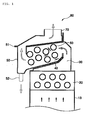
- Fig. 1 shows a latent heat absorbing apparatus 80 according to the present invention
- Fig. 2 shows a gas boiler 10 provided with the latent heat absorbing apparatus 80 of the invention
- Figs. 3 and 4 show a tube 61 of the latent heat absorbing apparatus 80 of the invention.
- the latent heat absorbing apparatus 80 is installed above a combustion chamber 13 of the gas boiler 10.
- the gas boiler 10 includes a blower 11, a burner 12, a sensible heat exchanger 20 and a first duct 30.
- the blower 11 is installed below the lowermost portion of the gas boiler 10.
- the blower 11 includes a motor that rotates with the application of electric power supplied thereto from the outside and a blowing fan rotated by a rotational force of the motor.
- the blowing fan sucks air from the outside of the gas boiler 10 through an opening communicating with the outside, and then blows air into the gas boiler 10 through an opening communicating with the inside of the gas boiler 10.
- the burner 12 is located above the blower 11 to make an ignition for burning the air blown there into by the blower 11 and fuel including gas introduced through a fuel line in a mixed state.
- the combustion chamber 13 defines a space for combusting the air and the gas and has a box shape isolated from the outside of the gas boiler.
- the sensible heat exchanger 20 is arranged at an upper portion of the combustion chamber 13 and has a single or a plurality of tubes 61 allowing heating water to flow therein. Each of the tubes 61 is bent or folded in several portions to provide a box shape for the sensible heat exchanger 20.
- the first duct 30 is located above the uppermost portion of the combustion chamber 13 to communicate with not only the combustion chamber 13 but also the outside of the combustion chamber.
- the first duct 30 has, at a portion communicating with the combustion chamber 13, a cross sectional area larger than that at a portion communicating with a chamber 50, which will be described below, so that exhaust gas from the combustion chamber 13 flows faster at the outlet of the first duct 30 than the inlet thereof.
- the latent heat absorbing apparatus 80 comprises a chamber 50, a cover 51, a second duct 70, a latent heat exchanger 60, a drain 52 and a heat shielding plate 40.
- the chamber 50 is located above the upper end of the first duct 30 such that the chamber 50 is very close to the first duct 30, and has a box shape opened at the top thereof.
- the chamber 50 is opened at a portion connected with the first duct 30 such that the chamber communicates with an opening of the first duct.
- the cover 51 has a plate shape to close the top of the chamber 50 opened, and is also opened at a connected portion with a second duct 70, which will be described below, such that the chamber 50 communicates with the second duct 70.
- the cover 51 is mounted on the chamber 50 with a fastening member including a bolt such that when mounting, for example, the latent heat exchanger 60 into the chamber 50 or repairing it in the chamber, the cover 51 is separated from the upper end of the chamber 50 to open the chamber 50.
- the communicating portion between the chamber 50 and the first duct 30 and the communicating portion between the cover 51 and the second duct 70 are provided at opposite ends, respectively, such that the exhaust gas can be transferred from one side of the chamber 50 to the other side thereof.
- the second duct 70 is installed on the upper end of the cover 50 such that the second duct is very close to the cover. At one side of the second duct 70, an opening is provided at the bottom thereof to communicate with the opening provided at one end of the cover 51. At the other side of the second duct 70, a tubular shape opening is provided at the top thereof to communicate with the outside of the gas boiler.
- the latent heat exchanger 60 is provided with a single or a plurality of tubes 61 therein such that each of the tubes is bent or folded in several portions to provide a box-like shape for the latent heat exchanger 60 to have a shape similar to that of the sensible heat exchanger 20. Further, the latent heat exchanger 60 has an outer shape fitted to the inside of the chamber 50 such that the latent heat exchanger 60 is attached to the inside of the chamber 50 after being mounted therein.
- the drain 52 is formed at one side of the bottom of the chamber 50 such that condensed water filled in the chamber 50 can be discharged out.
- the drain 52 is provided to have a tubular shape with a predetermined width outwardly protruded from the chamber 50.
- the chamber 50 communicates with the first duct 30 at one end of the chamber 50 and with the second duct 70 at the other end thereof.
- the drain 52 is provided for the chamber 50 to communicate with the outside thereof.
- the bottom of the chamber 50 is slanted toward the drain 52 to be lowered compared with other parts such that the condensed water can be easily discharged to the outside through the drain 52.
- the heat shielding plate 40 has a plate shape, the same as that of the underside of the chamber 50, such that the heat shielding plate is attached to the underside of the chamber 50.
- the heat shielding plate 40 is interposed into a region where the chamber 50 and the first duct 30 face each other, such that one end of the heat shielding plate 40 is connected to a lower portion of the chamber 50 and the other end thereof is connected to an upper portion of the first duct 30.
- the heat shielding plate 40 is made of a material, such as ceramic, to prevent heat transition caused by a temperature difference between the combustion chamber 13 and the chamber 50.
- each tube 61 with a cylindrical tubular shape is provided with a plurality of fins arranged on the outer surface of the tube in the direction of the exhaust gas flowing on the tubes (Highly Finned Tube) .
- each tube 61 may have a fin structure different from that of Fig. 3.
- each tube may be provided with a protrusion and groove spirally extending along the tube on the inner and outer surfaces thereof (Spiral Tube). In either case, each tube has a relatively larger fin area in contact with the exhaust gas filled in the chamber 50 without interfering with the flow of the exhaust gas into the chamber 50.
- the tube 61 is made of a corrosion resistant aluminium material and the tube 62 is made of a corrosion resistance stainless steel material.
- the exhaust gas flows into the latent heat absorbing apparatus 80 through the first duct 30 installed on the sensible heat exchanger 20.
- the exhaust gas from the combustion chamber 13 to the first duct 30 flows faster when passing through the outlet of the first duct 30.
- the exhaust gas accelerated in the first duct 30 flows into the chamber 50 communicating with the first duct 30 of the latent heat exchanger 80.
- the exhaust gas transferred into the chamber 50 flows into the latent heat exchanger 60 in the chamber 50, so that the heating water in the tubes 61 is heated and so that the heat of the exhaust gas is exchanged on the tubes 61 of the latent heat exchanger 60.
- the exhaust gas subjected to the heat exchange on the tubes 61 is discharged out of the gas boiler 10 through the opening communicating with the second duct 70 above the chamber 50.
- the exhaust gas flowing on tubes 61 of the latent heat exchanger 60 smoothly flows with reduced flow resistance of the gas by the tubes, each of which has the shape of a plurality of fins arranged on the outer surface thereof in the direction of the exhaust gas flow on the tube, as shown in Fig. 3, or the shape of a relatively low protrusion spirally extending along the outer surface thereof, as shown in Fig. 4.
- each tube has the shape of the fins arranged on the tube in the direction of the exhaust gas flowing on the tubes or the shape of the outwardly protruded fins extending spirally thereon.
- the present invention is not limited to these fin shapes.
- each tube may be provided with fins having holes perforated thereon in order to reduce the flow resistance of the gas.
- the heat transition from the sensible heat exchanger 20 of a relatively high temperature to the latent heat exchanger 60 is prevented by the chamber 50 separating the latent heat exchanger 60 from the sensible heat exchanger 20.
- the heat exchange is stably carried out in the combustion chamber 13 and the chamber 50 without outside influence.
- the chamber 50 has the bottom slanted toward the drain 52 formed at one side of the bottom of the chamber 50, even though the condensed water produced in the latent heat exchanger 60 falls to the bottom of the chamber 50, it flows along the shape of the bottom of the chamber 50 toward the drain 52 due to the force of the gravity, and is then discharged out of the gas boiler 10 through the drain 52.
- Assembly of the latent heat exchanger 60 into the chamber 50 or repair thereof can be accomplished with the upper side of the chamber 50 opened by separating the cover 51 fastened to the upper end of the chamber 50.
Landscapes
- Engineering & Computer Science (AREA)
- Physics & Mathematics (AREA)
- Thermal Sciences (AREA)
- Mechanical Engineering (AREA)
- General Engineering & Computer Science (AREA)
- Chemical & Material Sciences (AREA)
- Combustion & Propulsion (AREA)
- Geometry (AREA)
- Instantaneous Water Boilers, Portable Hot-Water Supply Apparatuses, And Control Of Portable Hot-Water Supply Apparatuses (AREA)
Applications Claiming Priority (2)
| Application Number | Priority Date | Filing Date | Title |
|---|---|---|---|
| KR2003031461 | 2003-10-07 | ||
| KR20030031461U KR200338878Y1 (ko) | 2003-10-07 | 2003-10-07 | 가스보일러용 잠열흡수장치 |
Publications (1)
| Publication Number | Publication Date |
|---|---|
| EP1522801A1 true EP1522801A1 (de) | 2005-04-13 |
Family
ID=34374104
Family Applications (1)
| Application Number | Title | Priority Date | Filing Date |
|---|---|---|---|
| EP04356054A Withdrawn EP1522801A1 (de) | 2003-10-07 | 2004-04-19 | Latentwärmeabsorber für Gaskessel |
Country Status (3)
| Country | Link |
|---|---|
| EP (1) | EP1522801A1 (de) |
| KR (1) | KR200338878Y1 (de) |
| CN (1) | CN1605812A (de) |
Cited By (7)
| Publication number | Priority date | Publication date | Assignee | Title |
|---|---|---|---|---|
| US20090288813A1 (en) * | 2008-05-26 | 2009-11-26 | Daesung Industrial Corporation | Structure of Heat Exchange Apparatus for Gas Boiler |
| CN101782270A (zh) * | 2010-02-26 | 2010-07-21 | 艾欧史密斯(中国)热水器有限公司 | 冷凝式燃气锅炉 |
| JP2015155786A (ja) * | 2014-02-21 | 2015-08-27 | 株式会社ノーリツ | 消音機能を備えた熱交換器 |
| JP2015158328A (ja) * | 2014-02-25 | 2015-09-03 | 株式会社ノーリツ | 排気集合筒 |
| EP2604944A4 (de) * | 2010-08-12 | 2016-06-01 | Kyungdong Navien Co Ltd | Latenter wärmetauscher in einem kondensationsboiler |
| JP2018141598A (ja) * | 2017-02-28 | 2018-09-13 | 株式会社ノーリツ | 熱交換器および熱源機 |
| WO2023033193A1 (en) * | 2021-09-01 | 2023-03-09 | Kim Hyon Il | Boiler comprising heat shield structure |
Families Citing this family (12)
| Publication number | Priority date | Publication date | Assignee | Title |
|---|---|---|---|---|
| KR20090067760A (ko) * | 2007-12-21 | 2009-06-25 | 주식회사 경동나비엔 | 상향 연소식 콘덴싱 보일러의 열교환기 |
| CN101832645B (zh) * | 2010-05-20 | 2012-02-29 | 浙江上能锅炉有限公司 | 一种真空热水锅炉的蒸发室 |
| CN102384588B (zh) * | 2011-10-31 | 2014-07-30 | 广东万家乐燃气具有限公司 | 一种用于燃气热水器的倒v形结构冷凝换热器 |
| CN102589128B (zh) * | 2012-02-07 | 2017-07-28 | 海尔集团公司 | 冷凝式燃气热水器双进风换热装置 |
| RU2684360C2 (ru) * | 2014-11-25 | 2019-04-08 | Киунгдонг Навиен Ко., Лтд. | Конденсационный котел |
| KR101749063B1 (ko) | 2016-07-06 | 2017-06-20 | 주식회사 경동나비엔 | 콘덴싱 보일러 |
| KR102240319B1 (ko) | 2018-06-05 | 2021-04-29 | 주식회사 경동나비엔 | 열교환기 유닛 |
| KR102536797B1 (ko) | 2018-06-05 | 2023-05-26 | 주식회사 경동나비엔 | 열교환배관을 포함하는 열교환기 유닛 및 이를 이용한 콘덴싱 보일러 |
| WO2019235780A1 (ko) | 2018-06-05 | 2019-12-12 | 주식회사 경동나비엔 | 열교환기 유닛 및 이를 이용한 콘덴싱 보일러 |
| KR102546285B1 (ko) | 2019-12-30 | 2023-06-23 | 주식회사 경동나비엔 | 열교환기 유닛 |
| CN114321963B (zh) * | 2021-12-27 | 2025-03-28 | 湖南金牛化工有限公司 | 一种用于锅炉烟气余热利用系统的换热器结构 |
| CN116336661A (zh) * | 2023-03-28 | 2023-06-27 | 芜湖美的智能厨电制造有限公司 | 冷凝换热器和燃气设备 |
Citations (3)
| Publication number | Priority date | Publication date | Assignee | Title |
|---|---|---|---|---|
| GB2043850A (en) * | 1978-12-22 | 1980-10-08 | Nederlandse Gasunie Nv | Boilers for Central Heating Systems |
| US4651680A (en) * | 1985-07-25 | 1987-03-24 | Service National: Gaz De France | Reduced wreath condensation boiler |
| EP0945688A2 (de) * | 1998-03-25 | 1999-09-29 | Ravenheat Manufacturing Limited | Kessel |
-
2003
- 2003-10-07 KR KR20030031461U patent/KR200338878Y1/ko not_active Expired - Lifetime
-
2004
- 2004-04-09 CN CNA2004100337187A patent/CN1605812A/zh active Pending
- 2004-04-19 EP EP04356054A patent/EP1522801A1/de not_active Withdrawn
Patent Citations (3)
| Publication number | Priority date | Publication date | Assignee | Title |
|---|---|---|---|---|
| GB2043850A (en) * | 1978-12-22 | 1980-10-08 | Nederlandse Gasunie Nv | Boilers for Central Heating Systems |
| US4651680A (en) * | 1985-07-25 | 1987-03-24 | Service National: Gaz De France | Reduced wreath condensation boiler |
| EP0945688A2 (de) * | 1998-03-25 | 1999-09-29 | Ravenheat Manufacturing Limited | Kessel |
Cited By (8)
| Publication number | Priority date | Publication date | Assignee | Title |
|---|---|---|---|---|
| US20090288813A1 (en) * | 2008-05-26 | 2009-11-26 | Daesung Industrial Corporation | Structure of Heat Exchange Apparatus for Gas Boiler |
| US8191512B2 (en) * | 2008-05-26 | 2012-06-05 | Daesung Industrial Corporation | Structure of heat exchange apparatus for gas boiler |
| CN101782270A (zh) * | 2010-02-26 | 2010-07-21 | 艾欧史密斯(中国)热水器有限公司 | 冷凝式燃气锅炉 |
| EP2604944A4 (de) * | 2010-08-12 | 2016-06-01 | Kyungdong Navien Co Ltd | Latenter wärmetauscher in einem kondensationsboiler |
| JP2015155786A (ja) * | 2014-02-21 | 2015-08-27 | 株式会社ノーリツ | 消音機能を備えた熱交換器 |
| JP2015158328A (ja) * | 2014-02-25 | 2015-09-03 | 株式会社ノーリツ | 排気集合筒 |
| JP2018141598A (ja) * | 2017-02-28 | 2018-09-13 | 株式会社ノーリツ | 熱交換器および熱源機 |
| WO2023033193A1 (en) * | 2021-09-01 | 2023-03-09 | Kim Hyon Il | Boiler comprising heat shield structure |
Also Published As
| Publication number | Publication date |
|---|---|
| KR200338878Y1 (ko) | 2004-01-16 |
| CN1605812A (zh) | 2005-04-13 |
Similar Documents
| Publication | Publication Date | Title |
|---|---|---|
| US5437263A (en) | High efficiency furnace method and apparatus | |
| US4848314A (en) | Condensing furnace | |
| US8191512B2 (en) | Structure of heat exchange apparatus for gas boiler | |
| KR200338878Y1 (ko) | 가스보일러용 잠열흡수장치 | |
| US4416325A (en) | Heat exchanger | |
| CA2141532C (en) | Dual drainage slope recuperative heat exchanger assembly for fuel-fired condensing furnaces | |
| US4738307A (en) | Heat exchanger for condensing furnace | |
| US6662758B1 (en) | Condensing gas boiler for recollecting condensed latent heat using uptrend combustion | |
| EP0073560B1 (de) | Brennstoffbeheizter Flüssigkeitserhitzer | |
| CA1211016A (en) | Compact high efficiency furnace | |
| US4947548A (en) | Method of making a heat exchanger for condensing furnace | |
| JP2003343926A (ja) | コンデンシングガスボイラーの熱交換器配置構造 | |
| EP0085470A2 (de) | Kessel mit Rauchgaskondensation | |
| CA2127923C (en) | High efficiency fuel-fired condensing furnace having a compact heat exchanger system | |
| KR20020000703A (ko) | 가스보일러의 콘덴싱 방식 열교환기 | |
| EP0459785B1 (de) | Heisswasserkessel | |
| RU2194920C2 (ru) | Усовершенствованный конденсационный котел с предварительным смешением для систем коммунально-бытового водоснабжения и отопительных систем | |
| KR200376666Y1 (ko) | 가스보일러용 잠열흡수장치 | |
| WO1985000649A1 (en) | Improvements in heating boilers | |
| KR100391895B1 (ko) | 콘덴싱 보일러의 상향 연소식 열교환기 구조 | |
| KR100392594B1 (ko) | 콘덴싱 가스보일러 | |
| KR100581589B1 (ko) | 콘덴싱 보일러의 잠열 열교환기 | |
| KR102837914B1 (ko) | 가스 난방장치 | |
| US2886295A (en) | Heat exchanger for warm air furnaces | |
| KR100449413B1 (ko) | 고부하 예혼합 버너를 갖는 콘덴싱 가스보일러 |
Legal Events
| Date | Code | Title | Description |
|---|---|---|---|
| PUAI | Public reference made under article 153(3) epc to a published international application that has entered the european phase |
Free format text: ORIGINAL CODE: 0009012 |
|
| AK | Designated contracting states |
Kind code of ref document: A1 Designated state(s): AT BE BG CH CY CZ DE DK EE ES FI FR GB GR HU IE IT LI LU MC NL PL PT RO SE SI SK TR |
|
| AX | Request for extension of the european patent |
Extension state: AL HR LT LV MK |
|
| 17P | Request for examination filed |
Effective date: 20050506 |
|
| AKX | Designation fees paid |
Designated state(s): DE FR GB IT NL |
|
| STAA | Information on the status of an ep patent application or granted ep patent |
Free format text: STATUS: THE APPLICATION IS DEEMED TO BE WITHDRAWN |
|
| 18D | Application deemed to be withdrawn |
Effective date: 20060527 |