EP1522812A2 - Plattenwärmetauscher zum Trocknen eines gasförmigen Mediums - Google Patents
Plattenwärmetauscher zum Trocknen eines gasförmigen Mediums Download PDFInfo
- Publication number
- EP1522812A2 EP1522812A2 EP04023607A EP04023607A EP1522812A2 EP 1522812 A2 EP1522812 A2 EP 1522812A2 EP 04023607 A EP04023607 A EP 04023607A EP 04023607 A EP04023607 A EP 04023607A EP 1522812 A2 EP1522812 A2 EP 1522812A2
- Authority
- EP
- European Patent Office
- Prior art keywords
- heat exchanger
- gas
- plates
- stack
- adjacent
- Prior art date
- Legal status (The legal status is an assumption and is not a legal conclusion. Google has not performed a legal analysis and makes no representation as to the accuracy of the status listed.)
- Granted
Links
- 238000001035 drying Methods 0.000 title claims description 7
- 239000002826 coolant Substances 0.000 claims abstract description 9
- 239000003507 refrigerant Substances 0.000 claims description 15
- 230000001404 mediated effect Effects 0.000 claims description 6
- 239000000463 material Substances 0.000 claims description 5
- 238000001816 cooling Methods 0.000 claims description 2
- 238000004519 manufacturing process Methods 0.000 description 6
- 238000000034 method Methods 0.000 description 3
- 239000002245 particle Substances 0.000 description 2
- 206010013786 Dry skin Diseases 0.000 description 1
- 230000015572 biosynthetic process Effects 0.000 description 1
- 239000007767 bonding agent Substances 0.000 description 1
- 239000003795 chemical substances by application Substances 0.000 description 1
- 238000009833 condensation Methods 0.000 description 1
- 230000005494 condensation Effects 0.000 description 1
- 230000002349 favourable effect Effects 0.000 description 1
- 230000002093 peripheral effect Effects 0.000 description 1
- 239000004033 plastic Substances 0.000 description 1
- 230000000284 resting effect Effects 0.000 description 1
- 238000005476 soldering Methods 0.000 description 1
- 239000007787 solid Substances 0.000 description 1
Images
Classifications
-
- F—MECHANICAL ENGINEERING; LIGHTING; HEATING; WEAPONS; BLASTING
- F28—HEAT EXCHANGE IN GENERAL
- F28D—HEAT-EXCHANGE APPARATUS, NOT PROVIDED FOR IN ANOTHER SUBCLASS, IN WHICH THE HEAT-EXCHANGE MEDIA DO NOT COME INTO DIRECT CONTACT
- F28D9/00—Heat-exchange apparatus having stationary plate-like or laminated conduit assemblies for both heat-exchange media, the media being in contact with different sides of a conduit wall
- F28D9/0093—Multi-circuit heat-exchangers, e.g. integrating different heat exchange sections in the same unit or heat-exchangers for more than two fluids
-
- F—MECHANICAL ENGINEERING; LIGHTING; HEATING; WEAPONS; BLASTING
- F28—HEAT EXCHANGE IN GENERAL
- F28D—HEAT-EXCHANGE APPARATUS, NOT PROVIDED FOR IN ANOTHER SUBCLASS, IN WHICH THE HEAT-EXCHANGE MEDIA DO NOT COME INTO DIRECT CONTACT
- F28D9/00—Heat-exchange apparatus having stationary plate-like or laminated conduit assemblies for both heat-exchange media, the media being in contact with different sides of a conduit wall
-
- F—MECHANICAL ENGINEERING; LIGHTING; HEATING; WEAPONS; BLASTING
- F28—HEAT EXCHANGE IN GENERAL
- F28D—HEAT-EXCHANGE APPARATUS, NOT PROVIDED FOR IN ANOTHER SUBCLASS, IN WHICH THE HEAT-EXCHANGE MEDIA DO NOT COME INTO DIRECT CONTACT
- F28D21/00—Heat-exchange apparatus not covered by any of the groups F28D1/00 - F28D20/00
- F28D2021/0019—Other heat exchangers for particular applications; Heat exchange systems not otherwise provided for
- F28D2021/0038—Other heat exchangers for particular applications; Heat exchange systems not otherwise provided for for drying or dehumidifying gases or vapours
Definitions
- the invention is in the field of plate heat exchangers for drying a gaseous Medium, especially air.
- Gaseous media such as air
- the gaseous medium usually has certain Meet properties for the production process, for example, a predetermined Purity or have a minimum moisture content.
- plate heat exchangers which are used to a gaseous medium, For example, compressed air to dry, so that the gaseous Medium only has a predetermined moisture content.
- the gaseous medium is introduced into the plate heat exchanger through an input port fed. Subsequently, the thus fed moist incoming gas stream flows through a Gas-gas heat exchanger.
- the gas-gas heat exchanger is in the plate heat exchanger in formed a portion of a stack of plates, which are used to form flow areas between the plates are interconnected.
- the incoming moist gas flow away from the input port and a dried one Output gas stream, which are then fed back into the production process can, to an output terminal through separate flow areas in the plate stack.
- the moist input gas stream and the dried starting gas stream flow in countercurrent, on the one hand to pre-cool the moist incoming gas stream.
- the dried starting gas stream by heat transfer from the wet inlet gas stream heated to the previously dried starting gas stream.
- the moist input gas stream passes from the gas-gas heat exchanger in this case Gas-refrigerant heat exchanger in the plate stack, which also has several flow areas between the plates of the stack.
- the gas-refrigerant heat exchanger flow the precooled input gas stream and a countercurrent refrigerant, so that the moist incoming gas stream is cooled, resulting in the subsequent convection of the moisture particles the input gas stream leads, so that the input gas stream is dried.
- the dried starting gas stream formed in this way flows through an overflow component from the outlet of the gas-refrigerant heat exchanger to the gas-gas heat exchanger, where it is reheated by absorbing heat from the incoming input gas stream.
- the thus heated starting gas stream flows through the output port of the plate heat exchanger for further use.
- the object of the invention is therefore to provide a plate heat exchanger for drying a gaseous Specify medium, which under operating conditions, a high pressurization allowed and holds this state, so that the safety standards are guaranteed.
- the invention includes the idea of using a plate heat exchanger for drying a gaseous medium, in particular air, which in a stack of plates, a gas-gas heat exchanger and a gas-refrigerant heat exchanger, an overflow component in a flow connection between the outlet of the gas-refrigerant heat exchanger and the gas-gas heat exchanger by means of a stack of adjacent ones Form plates, which form to overflow areas between the adjacent Plates are interconnected, wherein between facing side surfaces of the adjacent Plate contact areas are formed, in which the facing side surfaces connected to each other.
- a direct contact between the produced facing side surfaces of the adjacent plates of Matterströmbauteils wherein the contact may optionally be mediated by a suitable connecting means.
- An expedient embodiment of the invention provides that the adjacent plates at the deflecting component are soldered together, whereby on the one hand a reliable solid connection the adjacent plates is guaranteed.
- this way can Connecting the adjacent plates of Matterströmbauteils the same manufacturing technology used, as it is commonly used for connecting the plates of the stack in which the gas-gas heat exchanger and the gas-refrigerant heat exchanger are formed.
- the contact areas in the Kochströmbauteil edge contact areas include, in which, optionally mediated by a connecting material, edge portions of the facing side surfaces of the Touch adjacent plates. In this way, a peripheral on the edge of Kochströmbauteils pressure-resistant connection between the adjacent plates of the stack in the Overflow component allows.
- the contact areas in the overflow component comprise surface contact areas in which, optionally mediated by a connecting material in each case in a central region of adjacent plates of a plate plane projecting portions of the facing Touch side surfaces of adjacent plates.
- the strength of the adjacent plates of Matterströmbauteils is at a favorable Embodiment of the invention improved by the fact that the adjacent plates of the Kochströmbauteils have an embossed surface structure at least in some areas. hereby In particular, the surface stability of the adjacent plates of the overflow component optimized.
- a space-saving arrangement of Matterströmbauteils in the formation of the plate heat exchanger is achieved in a preferred embodiment of the invention in that the Kochströmbauteil arranged on an outer plate of the stack of plates surface resting is. In this way, as short as possible overflow connection between the Output promoted the gas-coolant heat exchanger and the gas-gas heat exchanger.
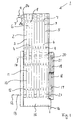
- FIG. 1 shows a plate heat exchanger 1 for drying a gaseous medium, in particular Air, in longitudinal section.
- the plate heat exchanger 1 comprises a stack 2 of a plurality of plates 3, which in the embodiment in the brazed plate heat exchanger are soldered together in the usual way, so that between the several plates 3 more Flow regions 4 are formed in a channel shape.
- a gas-gas heat exchanger In an upper section 5 of the plate heat exchanger 1 is a gas-gas heat exchanger with the aid of the plurality of plates 3 and the flow areas 4 6 formed.
- the gas-gas heat exchanger 6 flows a humid inlet gas stream 7, which is fed via an input terminal 8a, in the flow areas 4 down in countercurrent to an upwardly flowing output gas stream.
- the moist input gas stream flows 7 between the plates 3 in a lower portion 10 of the plate heat exchanger 1, in which a gas-refrigerant heat exchanger 11 is formed.
- a gas-refrigerant heat exchanger 11 is a coolant 12 via a coolant connection 13 between the plates. 3 fed so that the coolant 12 flows upwards between the plates 3, d. H. downhill flowing, moist incoming gas stream 7 against.
- Via a coolant outlet 14 the coolant 12 leaves the plate heat exchanger 1 and is itself a cooling again fed.
- the humid input gas flow 7 cooled below the predetermined dew point for each gaseous medium, so that Moisture components condense and in a separator 15 in the lower portion 10 of the Plate heat exchanger 1 are deposited. About an exit port 16, the condensed moisture particles are then removed.
- the thus cooled and dried gaseous medium flows after the condensation process via an overflow connection 17 back into the gas-gas heat exchanger. 6
- an overflow component 18 is arranged, in which overflow areas 19 are formed through which the dried starting gas stream is passed.
- the Mathströmbauteil 18 is formed by means of a stack 20 of a plurality of plates 21 at which facing side surfaces are connected to each other by means of contact areas.
- the contact regions include edge contact regions 22 and / or surface contact regions 23, in which, optionally mediated by a suitable bonding agent, for example Lot, the facing side surfaces touch. In this way, a pressure-resistant Kochströmbauteil 18 created.
- the surface contact regions 23 in particular Sections are used in the central area of the plurality of panels 21 in which the plurality Plates have 21 embossments, so that sections of the imprints adjacent Touch plates.
- the plate heat exchanger 1 may be lined internally with a suitable material, For example, a plastic which is resistant to the gaseous to be dried Medium is.
- moist compressed air can be dried which arises in different manufacturing processes.
- the dried compressed air or dried in other cases gaseous starting medium before leaving of the plate heat exchanger 1 through an output port 8b in the gas-gas heat exchanger 5 in the upward flow by heat transfer from the wet inlet gas stream 7 heated again, so that with the aid of the plate heat exchanger 1 a the process conditions adapted to a predetermined minimum temperature, heated Gas flow can be returned.
Landscapes
- Engineering & Computer Science (AREA)
- Physics & Mathematics (AREA)
- Thermal Sciences (AREA)
- Mechanical Engineering (AREA)
- General Engineering & Computer Science (AREA)
- Heat-Exchange Devices With Radiators And Conduit Assemblies (AREA)
- Drying Of Solid Materials (AREA)
- Fuel Cell (AREA)
Abstract
Description
- Figur 1
- einen Plattenwärmetauscher zum Trocknen eines gasförmigen Mediums im Längsschnitt.
Claims (8)
- Plattenwärmetauscher (1) zum Trocknen eines gasförmigen Mediums, insbesondere Luft, mit einem Stapel (2) von Platten (3), die zum Ausbilden von Strömungsbereichen (4) zwischen den Platten (3) miteinander verbunden sind, wobei in einem Abschnitt (5) des Stapels ein Gas-Gas-Wärmetauscher (6), in welchem zum Austausch von Wärmeenergie ein feuchter Eingangsgasstrom (7) von einem Eingangsanschluß (8a) weg und ein getrockneter Ausgangsgasstrom (9) zu einem Ausgangsanschluß (8b) hin durch getrennte Strömungsbereiche benachbart zueinander strömen, und in einem anderen Abschnitt (10) des Stapels ein Gas-Kühlmittel-Wärmetauscher (11) gebildet sind, in welchem zum Abkühlen der feuchte Eingangsgasstrom (7) und ein Kühlmittel (12) durch weitere getrennte Strömungsbereiche benachbart zueinander strömen, und wobei zwischen einem Ausgang des Gas-Kühlmittel-Wärmetauschers (11) und dem Gas-Gas-Wärmetauscher (6) eine Strömungsverbindung (17) gebildet ist, die ein Überströmbauteil (18) umfaßt, um den getrockneten Ausgangsgasstrom (9) über das Überströmbauteil (18) vom Ausgang des Gas-Kühlmittel-Wärmetauschers (11) zu dem Gas-Gas-Wärmetauscher (6) zu leiten, dadurch gekennzeichnet, daß das Überströmbauteil (18) mit Hilfe eines Stapels (20) von benachbarten Platten (21) gebildet ist, die zum Ausbilden von Überströmbereichen (19) zwischen den benachbarten Platten (21) miteinander verbunden sind, wobei zwischen sich zugewandten Seitenflächen der benachbarten Platten (21) Kontaktbereiche (22; 23) gebildet sind.
- Plattenwärmetauscher (1) nach Anspruch 1, dadurch gekennzeichnet, daß die benachbarten Platten (21) bei dem Überströmbauteil (18) miteinander verlötet sind.
- Plattenwärmetauscher (1) nach Anspruch 1 oder 2, dadurch gekennzeichnet, daß die Kontaktbereiche (22; 23) bei dem Überströmbauteil (18) Randkontaktbereiche (22) umfassen, in denen sich, wahlweise vermittelt durch ein Verbindungsmaterial, Randabschnitte der sich zugewandten Seitenflächen der benachbarten Platten (21) berühren.
- Plattenwärmetauscher (1) nach einem der vorangehenden Ansprüche, dadurch gekennzeichnet, daß die Kontaktbereiche (22; 23) bei dem Überströmbauteil (18) Flächenkontaktbereiche (23) umfassen, in denen sich, wahlweise vermittelt durch ein Verbindungsmaterial, jeweils in einem zentralen Bereich der benachbarten Platten (21) von einer Plattenebene vorstehende Abschnitte der sich zugewandten Seitenflächen der benachbarten Platten (21) berühren.
- Plattenwärmetauscher (1) nach einem der vorangehenden Ansprüche, dadurch gekennzeichnet, daß die benachbarten Platten (21) des Überströmbauteils (18) zumindest in Teilbereichen eine geprägte Oberflächenstruktur aufweisen.
- Plattenwärmetauscher (1) nach einem der vorangehenden Ansprüche, dadurch gekennzeichnet, daß das Überströmbauteil (18) auf einer Außenplatte des Stapels (2) von Platten (3) flächig aufliegend angeordnet ist.
- Plattenwärmetauscher (1) nach Anspruch 6, dadurch gekennzeichnet, daß das Überströmbauteil (18) auf die Außenplatte des Stapels (2) von Platten (3) aufgelötet ist.
- Plattenwärmetauscher (1) nach Anspruch 6 oder 7, dadurch gekennzeichnet, daß zwischen dem Überströmbauteil (18) und der Außenplatte des Stapels (2) von Platten (3) ein Abschnitt der Überströmbereiche (19) gebildet ist.
Applications Claiming Priority (2)
| Application Number | Priority Date | Filing Date | Title |
|---|---|---|---|
| DE10347880A DE10347880B4 (de) | 2003-10-10 | 2003-10-10 | Plattenwärmetauscher zum Trocknen eines gasförmigen Mediums |
| DE10347880 | 2003-10-10 |
Publications (3)
| Publication Number | Publication Date |
|---|---|
| EP1522812A2 true EP1522812A2 (de) | 2005-04-13 |
| EP1522812A3 EP1522812A3 (de) | 2007-11-21 |
| EP1522812B1 EP1522812B1 (de) | 2009-03-04 |
Family
ID=34306405
Family Applications (1)
| Application Number | Title | Priority Date | Filing Date |
|---|---|---|---|
| EP04023607A Expired - Lifetime EP1522812B1 (de) | 2003-10-10 | 2004-10-04 | Plattenwärmetauscher zum Trocknen eines gasförmigen Mediums |
Country Status (7)
| Country | Link |
|---|---|
| US (1) | US7789128B2 (de) |
| EP (1) | EP1522812B1 (de) |
| CN (1) | CN100339674C (de) |
| AT (1) | ATE424542T1 (de) |
| DE (2) | DE10347880B4 (de) |
| DK (1) | DK1522812T3 (de) |
| ES (1) | ES2322584T3 (de) |
Cited By (5)
| Publication number | Priority date | Publication date | Assignee | Title |
|---|---|---|---|---|
| EP2124010A3 (de) * | 2008-05-20 | 2013-11-20 | Parker Hannifin Manufacturing S.r.l. | Druckgastrockner auf Kühlungsbasis mit verbesserten Wärmetauschern |
| US20170030661A1 (en) * | 2015-07-30 | 2017-02-02 | Mahle Filter Systems Japan Corporation | Heat exchanger |
| AT518082B1 (de) * | 2016-03-31 | 2017-07-15 | Gerhard Kunze Dr | Klimatisierung durch Mehrphasen-Plattenwärmetauscher |
| US10228192B2 (en) | 2015-12-28 | 2019-03-12 | Mahle Filter Systems Japan Corporation | Heat exchanger |
| DE202019100507U1 (de) * | 2019-01-29 | 2020-05-12 | Akg Verwaltungsgesellschaft Mbh | Vorrichtung zur Abkühlung und Trocknung von Luft |
Families Citing this family (7)
| Publication number | Priority date | Publication date | Assignee | Title |
|---|---|---|---|---|
| US20050189097A1 (en) * | 2004-03-01 | 2005-09-01 | The Boeing Company | Formed sheet heat exchanger |
| EP2377596B9 (de) * | 2010-04-14 | 2016-04-13 | Kaeser Kompressoren Se | Kältetrockner, insbesondere druckluftkältetrockner, sowie wärmetauscher für einen kältetrockner, insbesondere druckluftkältetrockner |
| IT1403733B1 (it) * | 2011-02-07 | 2013-10-31 | Mta Spa | Apparato per l'essiccazione di gas. |
| JP5773353B2 (ja) * | 2011-02-15 | 2015-09-02 | 忠元 誠 | 熱交換器 |
| CN104006683A (zh) * | 2014-05-01 | 2014-08-27 | 铜陵钱谊化工设备有限责任公司 | 一种板式换热器 |
| IT201700119692A1 (it) * | 2017-10-23 | 2019-04-23 | Ceccato Aria Compressa S R L | Scambiatore di calore perfezionato e impianto di essiccazione dell’aria utilizzante il suddetto scambiatore di calore |
| DE102019119124A1 (de) * | 2019-07-15 | 2021-01-21 | Bayerische Motoren Werke Aktiengesellschaft | Kombinationswärmetauscher mit einem Chiller und einem inneren Wärmetauscher sowie Kühl-Kälte-Kreislaufsystem und Kraftfahrzeug mit einem solchen |
Citations (6)
| Publication number | Priority date | Publication date | Assignee | Title |
|---|---|---|---|---|
| US3797565A (en) | 1971-11-22 | 1974-03-19 | United Aircraft Prod | Refrigerated gas dryer |
| US5275233A (en) | 1993-01-25 | 1994-01-04 | Ingersoll-Rand Company | Apparatus for removing moisture from a hot compressed gas |
| DE4342598A1 (de) | 1993-12-14 | 1995-06-22 | Sabroe Gmbh Druckluft Und Gast | Vorrichtung zur Trocknung von Druckluft |
| DE19737205A1 (de) | 1997-08-27 | 1999-03-04 | Ultratroc Gmbh Drucklufttechni | Verfahren zum Betrieb von Kältedrucklufttrocknern |
| US20030041619A1 (en) | 2001-09-03 | 2003-03-06 | Yingzhong Lu | Integrated gas dehydrator |
| DE20315267U1 (de) | 2002-10-21 | 2004-03-04 | Autokühler GmbH & Co. KG | Vorrichtung zur Abkühlung und Trocknung von Luft, insbesondere für Kältemitteltrockner von Druckluftanlagen |
Family Cites Families (11)
| Publication number | Priority date | Publication date | Assignee | Title |
|---|---|---|---|---|
| US1781515A (en) * | 1928-03-14 | 1930-11-11 | Lewis Corp Inc | Humidifier and heater |
| US2808237A (en) * | 1953-02-16 | 1957-10-01 | Kenneth E Fosnes | Wall mounted air circulating heat exchangers |
| JPS50448A (de) * | 1973-05-09 | 1975-01-07 | ||
| US5434002A (en) * | 1990-06-04 | 1995-07-18 | Korea Institute Of Science And Technology | Non-spun, short, acrylic polymer, fibers |
| KR0124939B1 (ko) | 1990-06-04 | 1997-12-15 | 박원희 | 무방사 아크릴 단섬유 |
| DE4118289A1 (de) * | 1991-06-04 | 1992-12-10 | Autokuehler Gmbh & Co Kg | Waermetauscher-vorrichtung fuer kaeltetrockner an druckluftanlagen |
| FR2685071B1 (fr) * | 1991-12-11 | 1996-12-13 | Air Liquide | Echangeur de chaleur indirect du type a plaques. |
| JPH05312490A (ja) * | 1992-05-11 | 1993-11-22 | Hitachi Ltd | 積層熱交換器 |
| DE4426692C1 (de) * | 1994-07-28 | 1995-09-14 | Daimler Benz Ag | Zweistufige Verdampfereinheit für einen Reaktant-Massenstrom und Verfahren zur Herstellung desselben |
| US5845505A (en) * | 1997-05-30 | 1998-12-08 | American Precision Industries Inc. | Precooler/chiller/reheater heat exchanger for air dryers |
| DE10311602A1 (de) * | 2003-03-14 | 2004-09-23 | Agt Thermotechnik Gmbh | Vorrichtung, insbesondere Wärmetauscher, und Verfahren |
-
2003
- 2003-10-10 DE DE10347880A patent/DE10347880B4/de not_active Expired - Fee Related
-
2004
- 2004-10-04 DE DE502004009072T patent/DE502004009072D1/de not_active Expired - Fee Related
- 2004-10-04 DK DK04023607T patent/DK1522812T3/da active
- 2004-10-04 EP EP04023607A patent/EP1522812B1/de not_active Expired - Lifetime
- 2004-10-04 AT AT04023607T patent/ATE424542T1/de not_active IP Right Cessation
- 2004-10-04 ES ES04023607T patent/ES2322584T3/es not_active Expired - Lifetime
- 2004-10-08 US US10/962,379 patent/US7789128B2/en not_active Expired - Fee Related
- 2004-10-10 CN CNB2004100822515A patent/CN100339674C/zh not_active Expired - Fee Related
Patent Citations (6)
| Publication number | Priority date | Publication date | Assignee | Title |
|---|---|---|---|---|
| US3797565A (en) | 1971-11-22 | 1974-03-19 | United Aircraft Prod | Refrigerated gas dryer |
| US5275233A (en) | 1993-01-25 | 1994-01-04 | Ingersoll-Rand Company | Apparatus for removing moisture from a hot compressed gas |
| DE4342598A1 (de) | 1993-12-14 | 1995-06-22 | Sabroe Gmbh Druckluft Und Gast | Vorrichtung zur Trocknung von Druckluft |
| DE19737205A1 (de) | 1997-08-27 | 1999-03-04 | Ultratroc Gmbh Drucklufttechni | Verfahren zum Betrieb von Kältedrucklufttrocknern |
| US20030041619A1 (en) | 2001-09-03 | 2003-03-06 | Yingzhong Lu | Integrated gas dehydrator |
| DE20315267U1 (de) | 2002-10-21 | 2004-03-04 | Autokühler GmbH & Co. KG | Vorrichtung zur Abkühlung und Trocknung von Luft, insbesondere für Kältemitteltrockner von Druckluftanlagen |
Cited By (10)
| Publication number | Priority date | Publication date | Assignee | Title |
|---|---|---|---|---|
| EP2124010A3 (de) * | 2008-05-20 | 2013-11-20 | Parker Hannifin Manufacturing S.r.l. | Druckgastrockner auf Kühlungsbasis mit verbesserten Wärmetauschern |
| US20170030661A1 (en) * | 2015-07-30 | 2017-02-02 | Mahle Filter Systems Japan Corporation | Heat exchanger |
| CN106403666A (zh) * | 2015-07-30 | 2017-02-15 | 株式会社马勒滤清系统 | 热交换器 |
| US10234211B2 (en) * | 2015-07-30 | 2019-03-19 | Mahle Filter Systems Japan Corporation | Heat exchanger |
| CN106403666B (zh) * | 2015-07-30 | 2020-04-24 | 株式会社马勒滤清系统 | 热交换器 |
| US10228192B2 (en) | 2015-12-28 | 2019-03-12 | Mahle Filter Systems Japan Corporation | Heat exchanger |
| US10900716B2 (en) | 2015-12-28 | 2021-01-26 | Mahle Filter Systems Japan Corporation | Heat exchanger |
| AT518082B1 (de) * | 2016-03-31 | 2017-07-15 | Gerhard Kunze Dr | Klimatisierung durch Mehrphasen-Plattenwärmetauscher |
| AT518082A4 (de) * | 2016-03-31 | 2017-07-15 | Gerhard Kunze Dr | Klimatisierung durch Mehrphasen-Plattenwärmetauscher |
| DE202019100507U1 (de) * | 2019-01-29 | 2020-05-12 | Akg Verwaltungsgesellschaft Mbh | Vorrichtung zur Abkühlung und Trocknung von Luft |
Also Published As
| Publication number | Publication date |
|---|---|
| HK1078925A1 (zh) | 2006-03-24 |
| US20080210411A1 (en) | 2008-09-04 |
| US7789128B2 (en) | 2010-09-07 |
| EP1522812A3 (de) | 2007-11-21 |
| DK1522812T3 (da) | 2009-07-06 |
| DE10347880B4 (de) | 2007-10-31 |
| DE10347880A1 (de) | 2005-05-04 |
| ES2322584T3 (es) | 2009-06-23 |
| EP1522812B1 (de) | 2009-03-04 |
| ATE424542T1 (de) | 2009-03-15 |
| CN1707211A (zh) | 2005-12-14 |
| DE502004009072D1 (de) | 2009-04-16 |
| CN100339674C (zh) | 2007-09-26 |
Similar Documents
| Publication | Publication Date | Title |
|---|---|---|
| EP1522812B1 (de) | Plattenwärmetauscher zum Trocknen eines gasförmigen Mediums | |
| DE10035939A1 (de) | Vorrichtung zur Wärmeübertragung | |
| EP2010853A1 (de) | Mehrstufiger wärmetauschkanal mit parallel angeordnetem leitkanal | |
| DE3215961A1 (de) | Waermetauscher | |
| EP1452816A3 (de) | Plattenwärmetauscher | |
| DE69400794T2 (de) | Gaskompressionsverfahren und Vorrichtung | |
| DE2706253A1 (de) | Keramischer, rekuperativer gegenstromwaermetauscher | |
| DE3513936A1 (de) | Kuehleinrichtung fuer einen mehrstufigen verdichter | |
| EP1477761A2 (de) | Platten-Wärmeübertrager | |
| DE19648139A1 (de) | Gegenstromwärmetauscher | |
| DE3834941A1 (de) | Waermeaustauscher | |
| AT405376B (de) | Verfahren zur kühlung von schadstoffbeladenem heissem rohgas und anordnung zur durchführung des verfahrens | |
| WO2004081478A1 (de) | Wärmetauscher | |
| DE10213543A1 (de) | Wärmeübertrager für gasförmige Medien | |
| DE69515443T2 (de) | Vorrichtung zur Zirkulation eines Fluids | |
| WO2016155929A1 (de) | Vorrichtung und verfahren zur abscheidung von kohlendioxid aus einem gasstrom | |
| DE3630940C2 (de) | ||
| DE4118787A1 (de) | Prozessintegriertes betriebsfluessigkeitsreinigungssystem fuer verdichter | |
| DE112015003901B4 (de) | Sammelkammer für einen Wärmetauscher, Verbindungssystem und Wärmetauscher | |
| DE102018216047A1 (de) | Kühlstruktur | |
| DE3643749A1 (de) | Waermetauschermodul aus gebranntem keramischen material | |
| DE10150041B4 (de) | Austrag-Kühleinrichtung für eine Druckmaschine | |
| EP4177557B1 (de) | Wärmeübertragungsvorrichtung | |
| DE148330C (de) | ||
| DE10159839A1 (de) | Vorrichtung zur Belüftung von Innenräumen |
Legal Events
| Date | Code | Title | Description |
|---|---|---|---|
| PUAI | Public reference made under article 153(3) epc to a published international application that has entered the european phase |
Free format text: ORIGINAL CODE: 0009012 |
|
| AK | Designated contracting states |
Kind code of ref document: A2 Designated state(s): AT BE BG CH CY CZ DE DK EE ES FI FR GB GR HU IE IT LI LU MC NL PL PT RO SE SI SK TR |
|
| AX | Request for extension of the european patent |
Extension state: AL HR LT LV MK |
|
| REG | Reference to a national code |
Ref country code: HK Ref legal event code: DE Ref document number: 1078925 Country of ref document: HK |
|
| RAP1 | Party data changed (applicant data changed or rights of an application transferred) |
Owner name: GEA WTT GMBH |
|
| PUAL | Search report despatched |
Free format text: ORIGINAL CODE: 0009013 |
|
| AK | Designated contracting states |
Kind code of ref document: A3 Designated state(s): AT BE BG CH CY CZ DE DK EE ES FI FR GB GR HU IE IT LI LU MC NL PL PT RO SE SI SK TR |
|
| AX | Request for extension of the european patent |
Extension state: AL HR LT LV MK |
|
| 17P | Request for examination filed |
Effective date: 20080312 |
|
| AKX | Designation fees paid |
Designated state(s): AT BE BG CH CY CZ DE DK EE ES FI FR GB GR HU IE IT LI LU MC NL PL PT RO SE SI SK TR |
|
| GRAP | Despatch of communication of intention to grant a patent |
Free format text: ORIGINAL CODE: EPIDOSNIGR1 |
|
| GRAS | Grant fee paid |
Free format text: ORIGINAL CODE: EPIDOSNIGR3 |
|
| GRAA | (expected) grant |
Free format text: ORIGINAL CODE: 0009210 |
|
| AK | Designated contracting states |
Kind code of ref document: B1 Designated state(s): AT BE BG CH CY CZ DE DK EE ES FI FR GB GR HU IE IT LI LU MC NL PL PT RO SE SI SK TR |
|
| REG | Reference to a national code |
Ref country code: GB Ref legal event code: FG4D Free format text: NOT ENGLISH |
|
| REG | Reference to a national code |
Ref country code: CH Ref legal event code: EP |
|
| REG | Reference to a national code |
Ref country code: IE Ref legal event code: FG4D Free format text: LANGUAGE OF EP DOCUMENT: GERMAN |
|
| REF | Corresponds to: |
Ref document number: 502004009072 Country of ref document: DE Date of ref document: 20090416 Kind code of ref document: P |
|
| REG | Reference to a national code |
Ref country code: ES Ref legal event code: FG2A Ref document number: 2322584 Country of ref document: ES Kind code of ref document: T3 Ref country code: SE Ref legal event code: TRGR |
|
| REG | Reference to a national code |
Ref country code: DK Ref legal event code: T3 |
|
| PG25 | Lapsed in a contracting state [announced via postgrant information from national office to epo] |
Ref country code: SI Free format text: LAPSE BECAUSE OF FAILURE TO SUBMIT A TRANSLATION OF THE DESCRIPTION OR TO PAY THE FEE WITHIN THE PRESCRIBED TIME-LIMIT Effective date: 20090304 Ref country code: FI Free format text: LAPSE BECAUSE OF FAILURE TO SUBMIT A TRANSLATION OF THE DESCRIPTION OR TO PAY THE FEE WITHIN THE PRESCRIBED TIME-LIMIT Effective date: 20090304 |
|
| PG25 | Lapsed in a contracting state [announced via postgrant information from national office to epo] |
Ref country code: PL Free format text: LAPSE BECAUSE OF FAILURE TO SUBMIT A TRANSLATION OF THE DESCRIPTION OR TO PAY THE FEE WITHIN THE PRESCRIBED TIME-LIMIT Effective date: 20090304 |
|
| REG | Reference to a national code |
Ref country code: IE Ref legal event code: FD4D |
|
| PG25 | Lapsed in a contracting state [announced via postgrant information from national office to epo] |
Ref country code: PT Free format text: LAPSE BECAUSE OF FAILURE TO SUBMIT A TRANSLATION OF THE DESCRIPTION OR TO PAY THE FEE WITHIN THE PRESCRIBED TIME-LIMIT Effective date: 20090819 Ref country code: IE Free format text: LAPSE BECAUSE OF FAILURE TO SUBMIT A TRANSLATION OF THE DESCRIPTION OR TO PAY THE FEE WITHIN THE PRESCRIBED TIME-LIMIT Effective date: 20090304 Ref country code: EE Free format text: LAPSE BECAUSE OF FAILURE TO SUBMIT A TRANSLATION OF THE DESCRIPTION OR TO PAY THE FEE WITHIN THE PRESCRIBED TIME-LIMIT Effective date: 20090304 Ref country code: CZ Free format text: LAPSE BECAUSE OF FAILURE TO SUBMIT A TRANSLATION OF THE DESCRIPTION OR TO PAY THE FEE WITHIN THE PRESCRIBED TIME-LIMIT Effective date: 20090304 |
|
| REG | Reference to a national code |
Ref country code: HK Ref legal event code: GR Ref document number: 1078925 Country of ref document: HK |
|
| PG25 | Lapsed in a contracting state [announced via postgrant information from national office to epo] |
Ref country code: SK Free format text: LAPSE BECAUSE OF FAILURE TO SUBMIT A TRANSLATION OF THE DESCRIPTION OR TO PAY THE FEE WITHIN THE PRESCRIBED TIME-LIMIT Effective date: 20090304 Ref country code: RO Free format text: LAPSE BECAUSE OF FAILURE TO SUBMIT A TRANSLATION OF THE DESCRIPTION OR TO PAY THE FEE WITHIN THE PRESCRIBED TIME-LIMIT Effective date: 20090304 |
|
| PLBE | No opposition filed within time limit |
Free format text: ORIGINAL CODE: 0009261 |
|
| STAA | Information on the status of an ep patent application or granted ep patent |
Free format text: STATUS: NO OPPOSITION FILED WITHIN TIME LIMIT |
|
| PG25 | Lapsed in a contracting state [announced via postgrant information from national office to epo] |
Ref country code: BG Free format text: LAPSE BECAUSE OF FAILURE TO SUBMIT A TRANSLATION OF THE DESCRIPTION OR TO PAY THE FEE WITHIN THE PRESCRIBED TIME-LIMIT Effective date: 20090604 |
|
| 26N | No opposition filed |
Effective date: 20091207 |
|
| PG25 | Lapsed in a contracting state [announced via postgrant information from national office to epo] |
Ref country code: MC Free format text: LAPSE BECAUSE OF NON-PAYMENT OF DUE FEES Effective date: 20091031 |
|
| REG | Reference to a national code |
Ref country code: CH Ref legal event code: PL |
|
| PG25 | Lapsed in a contracting state [announced via postgrant information from national office to epo] |
Ref country code: DE Free format text: LAPSE BECAUSE OF NON-PAYMENT OF DUE FEES Effective date: 20100501 |
|
| PG25 | Lapsed in a contracting state [announced via postgrant information from national office to epo] |
Ref country code: LI Free format text: LAPSE BECAUSE OF NON-PAYMENT OF DUE FEES Effective date: 20091031 Ref country code: GR Free format text: LAPSE BECAUSE OF FAILURE TO SUBMIT A TRANSLATION OF THE DESCRIPTION OR TO PAY THE FEE WITHIN THE PRESCRIBED TIME-LIMIT Effective date: 20090605 Ref country code: CH Free format text: LAPSE BECAUSE OF NON-PAYMENT OF DUE FEES Effective date: 20091031 |
|
| PG25 | Lapsed in a contracting state [announced via postgrant information from national office to epo] |
Ref country code: AT Free format text: LAPSE BECAUSE OF NON-PAYMENT OF DUE FEES Effective date: 20091004 |
|
| PG25 | Lapsed in a contracting state [announced via postgrant information from national office to epo] |
Ref country code: LU Free format text: LAPSE BECAUSE OF NON-PAYMENT OF DUE FEES Effective date: 20091004 |
|
| PG25 | Lapsed in a contracting state [announced via postgrant information from national office to epo] |
Ref country code: HU Free format text: LAPSE BECAUSE OF FAILURE TO SUBMIT A TRANSLATION OF THE DESCRIPTION OR TO PAY THE FEE WITHIN THE PRESCRIBED TIME-LIMIT Effective date: 20090905 |
|
| PG25 | Lapsed in a contracting state [announced via postgrant information from national office to epo] |
Ref country code: TR Free format text: LAPSE BECAUSE OF FAILURE TO SUBMIT A TRANSLATION OF THE DESCRIPTION OR TO PAY THE FEE WITHIN THE PRESCRIBED TIME-LIMIT Effective date: 20090304 |
|
| PG25 | Lapsed in a contracting state [announced via postgrant information from national office to epo] |
Ref country code: CY Free format text: LAPSE BECAUSE OF FAILURE TO SUBMIT A TRANSLATION OF THE DESCRIPTION OR TO PAY THE FEE WITHIN THE PRESCRIBED TIME-LIMIT Effective date: 20090304 |
|
| PGFP | Annual fee paid to national office [announced via postgrant information from national office to epo] |
Ref country code: ES Payment date: 20140911 Year of fee payment: 11 |
|
| PGFP | Annual fee paid to national office [announced via postgrant information from national office to epo] |
Ref country code: DK Payment date: 20141010 Year of fee payment: 11 |
|
| PGFP | Annual fee paid to national office [announced via postgrant information from national office to epo] |
Ref country code: GB Payment date: 20141001 Year of fee payment: 11 |
|
| PGFP | Annual fee paid to national office [announced via postgrant information from national office to epo] |
Ref country code: NL Payment date: 20141010 Year of fee payment: 11 |
|
| PGFP | Annual fee paid to national office [announced via postgrant information from national office to epo] |
Ref country code: BE Payment date: 20141013 Year of fee payment: 11 |
|
| REG | Reference to a national code |
Ref country code: FR Ref legal event code: PLFP Year of fee payment: 12 |
|
| REG | Reference to a national code |
Ref country code: DK Ref legal event code: EBP Effective date: 20151031 |
|
| GBPC | Gb: european patent ceased through non-payment of renewal fee |
Effective date: 20151004 |
|
| REG | Reference to a national code |
Ref country code: NL Ref legal event code: MM Effective date: 20151101 |
|
| PG25 | Lapsed in a contracting state [announced via postgrant information from national office to epo] |
Ref country code: GB Free format text: LAPSE BECAUSE OF NON-PAYMENT OF DUE FEES Effective date: 20151004 |
|
| PG25 | Lapsed in a contracting state [announced via postgrant information from national office to epo] |
Ref country code: NL Free format text: LAPSE BECAUSE OF NON-PAYMENT OF DUE FEES Effective date: 20151101 |
|
| REG | Reference to a national code |
Ref country code: FR Ref legal event code: PLFP Year of fee payment: 13 |
|
| PG25 | Lapsed in a contracting state [announced via postgrant information from national office to epo] |
Ref country code: DK Free format text: LAPSE BECAUSE OF NON-PAYMENT OF DUE FEES Effective date: 20151031 |
|
| REG | Reference to a national code |
Ref country code: ES Ref legal event code: FD2A Effective date: 20161125 |
|
| PGFP | Annual fee paid to national office [announced via postgrant information from national office to epo] |
Ref country code: FR Payment date: 20160928 Year of fee payment: 13 |
|
| PG25 | Lapsed in a contracting state [announced via postgrant information from national office to epo] |
Ref country code: ES Free format text: LAPSE BECAUSE OF NON-PAYMENT OF DUE FEES Effective date: 20151005 |
|
| PGFP | Annual fee paid to national office [announced via postgrant information from national office to epo] |
Ref country code: IT Payment date: 20161024 Year of fee payment: 13 Ref country code: SE Payment date: 20161011 Year of fee payment: 13 |
|
| PG25 | Lapsed in a contracting state [announced via postgrant information from national office to epo] |
Ref country code: BE Free format text: LAPSE BECAUSE OF NON-PAYMENT OF DUE FEES Effective date: 20151031 |
|
| REG | Reference to a national code |
Ref country code: SE Ref legal event code: EUG |
|
| REG | Reference to a national code |
Ref country code: FR Ref legal event code: ST Effective date: 20180629 |
|
| PG25 | Lapsed in a contracting state [announced via postgrant information from national office to epo] |
Ref country code: SE Free format text: LAPSE BECAUSE OF NON-PAYMENT OF DUE FEES Effective date: 20171005 Ref country code: FR Free format text: LAPSE BECAUSE OF NON-PAYMENT OF DUE FEES Effective date: 20171031 |
|
| PG25 | Lapsed in a contracting state [announced via postgrant information from national office to epo] |
Ref country code: IT Free format text: LAPSE BECAUSE OF NON-PAYMENT OF DUE FEES Effective date: 20171004 |