EP1523081A2 - Portable charger for mobile phones - Google Patents
Portable charger for mobile phones Download PDFInfo
- Publication number
- EP1523081A2 EP1523081A2 EP04023902A EP04023902A EP1523081A2 EP 1523081 A2 EP1523081 A2 EP 1523081A2 EP 04023902 A EP04023902 A EP 04023902A EP 04023902 A EP04023902 A EP 04023902A EP 1523081 A2 EP1523081 A2 EP 1523081A2
- Authority
- EP
- European Patent Office
- Prior art keywords
- mobile phone
- battery
- voltage
- accommodation recess
- charging current
- Prior art date
- Legal status (The legal status is an assumption and is not a legal conclusion. Google has not performed a legal analysis and makes no representation as to the accuracy of the status listed.)
- Withdrawn
Links
Images






Classifications
-
- H—ELECTRICITY
- H02—GENERATION; CONVERSION OR DISTRIBUTION OF ELECTRIC POWER
- H02J—ELECTRIC POWER NETWORKS; CIRCUIT ARRANGEMENTS OR SYSTEMS FOR SUPPLYING OR DISTRIBUTING ELECTRIC POWER; SYSTEMS FOR STORING ELECTRIC ENERGY
- H02J7/00—Circuit arrangements for charging or discharging batteries or for supplying loads from batteries
- H02J7/70—Circuit arrangements for charging or discharging batteries or for supplying loads from batteries characterised by the mechanical construction
- H02J7/731—Circuit arrangements for charging or discharging batteries or for supplying loads from batteries characterised by the mechanical construction specially adapted for holding portable devices containing batteries
-
- A—HUMAN NECESSITIES
- A45—HAND OR TRAVELLING ARTICLES
- A45F—TRAVELLING OR CAMP EQUIPMENT: SACKS OR PACKS CARRIED ON THE BODY
- A45F5/00—Holders or carriers for hand articles; Holders or carriers for use while travelling or camping
-
- A—HUMAN NECESSITIES
- A45—HAND OR TRAVELLING ARTICLES
- A45F—TRAVELLING OR CAMP EQUIPMENT: SACKS OR PACKS CARRIED ON THE BODY
- A45F5/00—Holders or carriers for hand articles; Holders or carriers for use while travelling or camping
- A45F5/02—Fastening articles to the garment
- A45F5/021—Fastening articles to the garment to the belt
-
- H—ELECTRICITY
- H01—ELECTRIC ELEMENTS
- H01M—PROCESSES OR MEANS, e.g. BATTERIES, FOR THE DIRECT CONVERSION OF CHEMICAL ENERGY INTO ELECTRICAL ENERGY
- H01M50/00—Constructional details or processes of manufacture of the non-active parts of electrochemical cells other than fuel cells, e.g. hybrid cells
- H01M50/20—Mountings; Secondary casings or frames; Racks, modules or packs; Suspension devices; Shock absorbers; Transport or carrying devices; Holders
- H01M50/202—Casings or frames around the primary casing of a single cell or a single battery
-
- H—ELECTRICITY
- H01—ELECTRIC ELEMENTS
- H01M—PROCESSES OR MEANS, e.g. BATTERIES, FOR THE DIRECT CONVERSION OF CHEMICAL ENERGY INTO ELECTRICAL ENERGY
- H01M50/00—Constructional details or processes of manufacture of the non-active parts of electrochemical cells other than fuel cells, e.g. hybrid cells
- H01M50/20—Mountings; Secondary casings or frames; Racks, modules or packs; Suspension devices; Shock absorbers; Transport or carrying devices; Holders
- H01M50/244—Secondary casings; Racks; Suspension devices; Carrying devices; Holders characterised by their mounting method
-
- H—ELECTRICITY
- H01—ELECTRIC ELEMENTS
- H01M—PROCESSES OR MEANS, e.g. BATTERIES, FOR THE DIRECT CONVERSION OF CHEMICAL ENERGY INTO ELECTRICAL ENERGY
- H01M50/00—Constructional details or processes of manufacture of the non-active parts of electrochemical cells other than fuel cells, e.g. hybrid cells
- H01M50/20—Mountings; Secondary casings or frames; Racks, modules or packs; Suspension devices; Shock absorbers; Transport or carrying devices; Holders
- H01M50/247—Mountings; Secondary casings or frames; Racks, modules or packs; Suspension devices; Shock absorbers; Transport or carrying devices; Holders specially adapted for portable devices, e.g. mobile phones, computers, hand tools or pacemakers
-
- H—ELECTRICITY
- H01—ELECTRIC ELEMENTS
- H01M—PROCESSES OR MEANS, e.g. BATTERIES, FOR THE DIRECT CONVERSION OF CHEMICAL ENERGY INTO ELECTRICAL ENERGY
- H01M50/00—Constructional details or processes of manufacture of the non-active parts of electrochemical cells other than fuel cells, e.g. hybrid cells
- H01M50/20—Mountings; Secondary casings or frames; Racks, modules or packs; Suspension devices; Shock absorbers; Transport or carrying devices; Holders
- H01M50/262—Mountings; Secondary casings or frames; Racks, modules or packs; Suspension devices; Shock absorbers; Transport or carrying devices; Holders with fastening means, e.g. locks
-
- H—ELECTRICITY
- H01—ELECTRIC ELEMENTS
- H01M—PROCESSES OR MEANS, e.g. BATTERIES, FOR THE DIRECT CONVERSION OF CHEMICAL ENERGY INTO ELECTRICAL ENERGY
- H01M50/00—Constructional details or processes of manufacture of the non-active parts of electrochemical cells other than fuel cells, e.g. hybrid cells
- H01M50/20—Mountings; Secondary casings or frames; Racks, modules or packs; Suspension devices; Shock absorbers; Transport or carrying devices; Holders
- H01M50/296—Mountings; Secondary casings or frames; Racks, modules or packs; Suspension devices; Shock absorbers; Transport or carrying devices; Holders characterised by terminals of battery packs
-
- H—ELECTRICITY
- H02—GENERATION; CONVERSION OR DISTRIBUTION OF ELECTRIC POWER
- H02J—ELECTRIC POWER NETWORKS; CIRCUIT ARRANGEMENTS OR SYSTEMS FOR SUPPLYING OR DISTRIBUTING ELECTRIC POWER; SYSTEMS FOR STORING ELECTRIC ENERGY
- H02J4/00—Circuit arrangements for mains or distribution networks not specified as AC or DC; Circuit arrangements for mains or distribution networks combining AC and DC sections or sub-networks
- H02J4/20—Networks integrating separated AC and DC power sections
- H02J4/25—Networks integrating separated AC and DC power sections for transfer of electric power between AC and DC networks, e.g. for supplying the DC section within a load from an AC mains system
-
- H—ELECTRICITY
- H02—GENERATION; CONVERSION OR DISTRIBUTION OF ELECTRIC POWER
- H02J—ELECTRIC POWER NETWORKS; CIRCUIT ARRANGEMENTS OR SYSTEMS FOR SUPPLYING OR DISTRIBUTING ELECTRIC POWER; SYSTEMS FOR STORING ELECTRIC ENERGY
- H02J7/00—Circuit arrangements for charging or discharging batteries or for supplying loads from batteries
-
- H—ELECTRICITY
- H02—GENERATION; CONVERSION OR DISTRIBUTION OF ELECTRIC POWER
- H02J—ELECTRIC POWER NETWORKS; CIRCUIT ARRANGEMENTS OR SYSTEMS FOR SUPPLYING OR DISTRIBUTING ELECTRIC POWER; SYSTEMS FOR STORING ELECTRIC ENERGY
- H02J7/00—Circuit arrangements for charging or discharging batteries or for supplying loads from batteries
- H02J7/02—Circuit arrangements for charging or discharging batteries or for supplying loads from batteries for charging batteries from AC mains by converters
-
- H—ELECTRICITY
- H02—GENERATION; CONVERSION OR DISTRIBUTION OF ELECTRIC POWER
- H02J—ELECTRIC POWER NETWORKS; CIRCUIT ARRANGEMENTS OR SYSTEMS FOR SUPPLYING OR DISTRIBUTING ELECTRIC POWER; SYSTEMS FOR STORING ELECTRIC ENERGY
- H02J7/00—Circuit arrangements for charging or discharging batteries or for supplying loads from batteries
- H02J7/50—Circuit arrangements for charging or discharging batteries or for supplying loads from batteries acting upon multiple batteries simultaneously or sequentially
-
- A—HUMAN NECESSITIES
- A45—HAND OR TRAVELLING ARTICLES
- A45F—TRAVELLING OR CAMP EQUIPMENT: SACKS OR PACKS CARRIED ON THE BODY
- A45F5/00—Holders or carriers for hand articles; Holders or carriers for use while travelling or camping
- A45F2005/006—Holders or carriers for hand articles; Holders or carriers for use while travelling or camping comprising a suspension strap or lanyard
-
- A—HUMAN NECESSITIES
- A45—HAND OR TRAVELLING ARTICLES
- A45F—TRAVELLING OR CAMP EQUIPMENT: SACKS OR PACKS CARRIED ON THE BODY
- A45F5/00—Holders or carriers for hand articles; Holders or carriers for use while travelling or camping
- A45F5/02—Fastening articles to the garment
- A45F2005/025—Fastening articles to the garment with a holder or item rotatably connected to the fastening device, e.g. having a rotation axis perpendicular to the garment
-
- A—HUMAN NECESSITIES
- A45—HAND OR TRAVELLING ARTICLES
- A45F—TRAVELLING OR CAMP EQUIPMENT: SACKS OR PACKS CARRIED ON THE BODY
- A45F5/00—Holders or carriers for hand articles; Holders or carriers for use while travelling or camping
- A45F5/02—Fastening articles to the garment
-
- A—HUMAN NECESSITIES
- A45—HAND OR TRAVELLING ARTICLES
- A45F—TRAVELLING OR CAMP EQUIPMENT: SACKS OR PACKS CARRIED ON THE BODY
- A45F5/00—Holders or carriers for hand articles; Holders or carriers for use while travelling or camping
- A45F5/1516—Holders or carriers for portable handheld communication devices, e.g. pagers or smart phones
-
- H—ELECTRICITY
- H01—ELECTRIC ELEMENTS
- H01M—PROCESSES OR MEANS, e.g. BATTERIES, FOR THE DIRECT CONVERSION OF CHEMICAL ENERGY INTO ELECTRICAL ENERGY
- H01M10/00—Secondary cells; Manufacture thereof
- H01M10/42—Methods or arrangements for servicing or maintenance of secondary cells or secondary half-cells
- H01M10/46—Accumulators structurally combined with charging apparatus
-
- Y—GENERAL TAGGING OF NEW TECHNOLOGICAL DEVELOPMENTS; GENERAL TAGGING OF CROSS-SECTIONAL TECHNOLOGIES SPANNING OVER SEVERAL SECTIONS OF THE IPC; TECHNICAL SUBJECTS COVERED BY FORMER USPC CROSS-REFERENCE ART COLLECTIONS [XRACs] AND DIGESTS
- Y02—TECHNOLOGIES OR APPLICATIONS FOR MITIGATION OR ADAPTATION AGAINST CLIMATE CHANGE
- Y02E—REDUCTION OF GREENHOUSE GAS [GHG] EMISSIONS, RELATED TO ENERGY GENERATION, TRANSMISSION OR DISTRIBUTION
- Y02E60/00—Enabling technologies; Technologies with a potential or indirect contribution to GHG emissions mitigation
- Y02E60/10—Energy storage using batteries
Definitions
- the present invention relates generally to a portable charger for a mobile phone (also referred to as a mobile communication terminal or a portable phone) and, more particularly, to a portable charger for a mobile phone, which is easy to carry, can easily charge the battery of the mobile phone with direct current power charged in a secondary battery, and can simultaneously charge the secondary battery and the battery of the mobile phone using a travel adaptor.
- a mobile phone also referred to as a mobile communication terminal or a portable phone
- a portable charger for a mobile phone which is easy to carry, can easily charge the battery of the mobile phone with direct current power charged in a secondary battery, and can simultaneously charge the secondary battery and the battery of the mobile phone using a travel adaptor.
- a conventional portable charger equipped with an internal battery is disclosed in Korean Utility Model Registration No. 20-0275514 (registered on May 1, 2002).
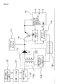
- an Alternating Current (AC) power connection unit 110 provided with a power plug 111 is attached to a side of a body 100 to allow the portable charger to be connected to a domestic power outlet, as shown in FIGS. 1 and 2.
- AC Alternating Current
- the power plug 111 can be retracted to a position parallel to the body 100 using a rotation shaft 112 provided on the body 100, so that it is secured in a position perpendicular to the body 100 when in use (indicated by dotted lines), and is retracted into a recess 113 when not in use (indicated by solid lines).
- a cable 151 and an interface jack 152 are provided on a side of the body 100 to allow the charger to be electrically connected to the interface connector (not shown) of a mobile phone.
- the internal terminals of the interface connector of the mobile phone are electrically connected to the positive (+) terminal, negative (-) terminal and identification data input (IN) terminal of an external battery connection unit 115.
- the charger is electrically connected to domestic 110V or 220V AC power through the AC power connection unit 110.
- An ElectroMagnetic Interference (EMI) filter 121 is connected to the AC power connection unit 110 to remove noise from AC power that is applied through the AC power connection unit 110.
- a rectifying unit 122 is connected to the EMI filter 121 to rectify the AC power, applied through the EMI filter 121, to Direct Current (DC) power and supply the DC power to a switching mode power supply unit 114.
- DC Direct Current
- the switching mode power supply unit 114 functions to receive the DC current from the rectifying unit, interrupt the DC current according to a duty ratio, and supply stepped-down charging current.
- the switching mode power supply unit 114 includes a coil unit 114a for producing the stepped-down current by interrupting the DC current input from the rectifying unit 122, and a switching control unit 114b for adjusting the amount of charging current flowing into the secondary battery by switching the coil unit 114a.
- the external battery connection unit 115 is connected to the interface connector of the mobile phone so that identification data (ID) transmitted from the battery identification terminal of the mobile phone is applied to a microprocessor 119 through an identification output terminal OUT.
- the interface jack 152 is provided with the positive (+) input terminal, the negative (-) input terminal and the identification data input (IN) terminal that are connected to the charging terminal, ground terminal and identification terminal of the battery of the mobile phone, respectively.
- a Pulse Width Modulation (PWM) control unit 116 adjusts the voltage level of current charging voltage based on a voltage control signal applied from the microprocessor 119 so that charging voltage applied to the external battery connection unit 115 reaches a specific reference voltage and is maintained at the specific reference voltage.
- the modulation signal output terminal of the PWM control unit 116 is connected to the base terminal of a transistor Q1, the output terminal of the switching mode power supply unit 114 is connected to the collector terminal of the transistor Q1, and the charging current input terminal of the external battery connection unit 115 as well as the voltage feedback signal input terminal of the PWM control unit 116 are connected to the emitter terminal of the transistor Q1.
- An internal battery 117 connected to the output terminal of the switching mode power supply unit 114 is a secondary battery that stores electrical energy using DC power, output from the switching mode power supply unit 114, as charging current.
- the internal battery 117 is charged with electricity to charge an external battery (battery of a mobile phone) that is connected to the external battery connection unit 115.
- the internal battery 117 is equipped with an overcharge prevention circuit to prevent overcharge.
- a photocoupler 118 is connected between the microprocessor 119 and the switching control unit 114b of the switching mode power supply unit 114 to convert a current control signal, applied by the microprocessor 119, into an optical signal, to convert the optical signal into an electrical signal having a specific duty ratio and to control the application of power to the switching mode power supply unit 114.
- the microprocessor 119 reads the identification data of the battery transmitted from the external battery connection unit 115, sets the maximum charging voltage and maximum charging current, and controls the switching mode power supply unit 114 and the PWM control unit 116 based on the maximum charging voltage and the maximum charging current.
- the user In the case where a user charges the battery of a mobile phone with domestic 110V or 220V AC power, the user inserts the power plug 111 of the AC power connection unit 120 into a domestic power outlet and connects the interface jack 152 to the interface connector (not shown) of the mobile phone.
- the noise-free AC power is rectified to DC power by the rectifying unit 122, and the DC power is applied to the switching mode power supply unit 114.
- the DC power applied to the switching mode power supply unit 114 is used to charge the battery of the mobile phone and the internal battery 117 under the control of the microprocessor 119.
- the microprocessor 119 After applying a current control signal, that is, a PWM modulation signal, to the photocoupler 118 based on the preset maximum charging voltage and charging current of the internal battery 117, the microprocessor 119 reads the identification data (ID) of the mobile phone transmitted from the external battery connection unit 115, sets the maximum charging voltage and maximum charging current for the battery of the mobile phone, and sets the reference voltage of the PWM control unit 116 to the maximum charging voltage of the battery of the mobile phone.
- ID identification data
- the photocoupler 118 outputs an electrical signal having a specific duty ratio to the switching control unit 114b to correspond to the current control signal transmitted from the microprocessor 119.
- the switching control unit 114b adjusts the amount of charging current, which will be supplied to the external battery connection unit 115 and the internal battery 117, by interrupting the operation of the coil unit 114a according to the duty ratio of the electrical signal.
- the PWM control unit 116 compares the voltage (current charged voltage of the battery of the mobile phone), applied to the emitter terminal of the transistor Q1 and the connection node of the external battery connection unit 115, with the preset reference voltage, and adjusts the period of ON/OFF operation of the transistor Q1 so that the current charged voltage reaches the preset reference voltage and is maintained at the preset reference voltage.
- the PWM control unit 116 When the current charged voltage reaches the reference voltage, the PWM control unit 116 indicates to the microprocessor 119 that current charged voltage has reached the reference voltage.
- the microprocessor 119 applies a current control signal to the photocoupler 118 in response to the information so that the amount of charging current output from the switching mode power supply unit 114 gradually decreases.
- the microprocessor 119 controls the operation of the switching mode power supply unit 114 according to the preset maximum charging voltage and current for the internal battery 117. Furthermore, the microprocessor 119 prevents overcharge of the battery connected to the external battery connection unit 115 by adjusting the amount of charging current that is output from the switching mode power supply unit 114 based on the current charged voltage of the mobile phone. When the internal battery 117 reaches a fully charged state, the microprocessor 119 detects the fully charged state using the overcharge prevention circuit and automatically blocks the inflow of charging current.
- the charging current output from the switching mode power supply unit 114 charges the internal battery 117 through a diode D1, and is applied to the external battery connection unit 115 and charges the battery of the mobile phone as well.
- the microprocessor 119 reads the identification data (ID) of the battery of the mobile phone transmitted from the external battery connection unit 115, sets the maximum charging voltage and current of the battery of the mobile phone, and sets the reference voltage of the PWM control unit 116 to the maximum charging voltage.
- ID identification data
- the PWM control unit 116 charges the battery of the mobile phone by comparing the current charged voltage of the battery of the mobile phone, connected to the external battery connection unit 115, with the preset reference voltage, and adjusting the period of ON/OFF operation of the transistor Q1 so that the current charged voltage reaches the preset reference voltage and is maintained at the preset reference voltage.
- the conventional portable charger equipped with an internal battery is capable of charging the battery of a mobile phone even at locations where domestic AC power and automobile battery power are not available
- the conventional charger is disadvantageous in that the conventional charger is not possible and the charging operation of the conventional charger is complicated and inconvenient because the cable 152, provided with the interface jack 152 that will be connected to the interface connector of a mobile phone, is required to charge the battery of the mobile phone and one end of the cable 152 must be electrically connected to the body 100.
- an object of the present invention is to provide a portable charger for a mobile phone that is easy to carry because it can be easily attached to and detached from a waist belt using a belt clip and the wearing position of the portable charger for a mobile phone can be changed through the rotation thereof when being worn on a waist belt.
- Another object of the present invention is to provide a portable charger for a mobile phone, which can simultaneously charge a secondary battery and the battery of a mobile phone with the DC power obtained by a travel adaptor.
- Still another object of the present invention is to provide a portable charger for a mobile phone, which can prevent charging power from being discharged from a secondary battery when the mobile phone is not electrically connected to the accommodation recess of the front housing of the portable charger for a mobile phone.
- Still another object of the present invention is to provide a portable charger for a mobile phone, which prevents charge when the surrounding temperature is equal to or higher than a predetermined temperature (for example, 45°C) or equal to or lower than a predetermined temperature (for example,-5°C).
- a predetermined temperature for example, 45°C
- a predetermined temperature for example,-5°C
- Still another object of the present invention is to provide a portable charger for a mobile phone, which can easily charge the battery of a mobile phone with the DC power charged in the secondary battery.
- Still another object of the present invention is to provide a portable charger for a mobile phone, which can easily charge the battery of a mobile phone using an automobile battery while connecting to a hands-free kit.
- Still another object of the present invention is to provide a portable charger for a mobile phone, which can simultaneously charge a secondary battery and the battery of a mobile phone using a travel adaptor while electrically connecting to a table charging stand.
- the present invention provides a portable charger for a mobile phone, including a front housing having an accommodation recess formed in the front side of the front housing to accommodate a mobile phone, and cutouts formed on the right and left sides of the upper portion of the accommodation recess to allow a user to easily grip the mobile phone seated in the accommodation recess and easily manipulate a volume key of the mobile phone; a rear housing fastened to the back of the front housing by screws to close the rear open side of the front housing; a belt clip detachably attached into a long accommodation recess formed on the back of the rear housing to change the mounting position of the rear housing; a fastening unit placed in the long accommodation recess formed on the back of the rear housing to prevent the belt clip from being removed from the accommodation recess; a pair of clamps rotatably placed on the right and left sidewalls of the accommodation recess formed in the front housing to prevent the mobile phone from being removed during charging while engaging with recesses formed on both sides of the mobile phone, respectively
- the present invention provides a portable charger for a mobile phone, including a front housing having an accommodation recess formed in the front side of the front housing to accommodate a mobile phone, and cutouts formed on the right and left sides of an upper portion of the accommodation recess to allow a user to easily grip the mobile phone seated in the accommodation recess and easily manipulate a volume key of the mobile phone; a rear housing fastened to the back of the front housing by screws to close the rear open side of the front housing; a belt clip detachably attached into a long accommodation recess formed on the back of the rear housing to change the mounting position of the rear housing; a fastening unit placed in the long accommodation recess formed on the back of the rear housing to prevent the belt clip from being removed from the accommodation recess; a pair of clamps rotatably placed on the right and left sidewalls of the accommodation recess formed in the front housing to prevent the mobile phone from being removed during charging while engaging with recesses formed on both sides of the mobile phone, respectively; a release button placed
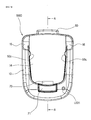
- FIG. 3 is a front view schematically showing a portable charger for a mobile phone according to an embodiment of the present invention.
- FIG. 4 is a right side view showing the portable charger for a mobile phone with a belt clip in a non-operational position.
- FIG. 5 is a right side view showing the portable charger for a mobile phone with the belt clip in an operational position.
- FIG. 6 is a longitudinal section taken along line A-A of FIG. 3 with a secondary battery and a charge control circuit removed therefrom.
- FIG. 7 is a rearward perspective view showing the portable charger for a mobile phone with the belt clip separated therefrom.
- FIG. 8 is a rearward perspective view showing the portable charger for a mobile phone with a coupling member is separated from the fastening member of the belt clip.
- FIG. 9 is a view showing the coupling member rotated by 90° clockwise and counterclockwise around the fastening member of the belt clip in the portable charger for a mobile phone according to the embodiment of the present invention.
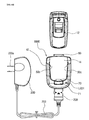
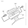
- FIG. 10 is a view showing the electrical connection of a charging cable to the portable charger for a mobile phone according to the embodiment of the present invention and the mounting of a mobile phone in the portable charger for a mobile phone according to the embodiment of the present invention.
- FIG. 11 is a view showing the mounting of a mobile phone in the portable charger for a mobile phone according to the embodiment of the present invention and the charging of the battery of the mobile phone using the secondary battery.
- FIG. 12 is a view showing the portable charger for a mobile phone with a release button not operated and a rear housing removed therefrom.
- FIG. 13 is an exploded view of the portable charger for a mobile phone according to the embodiment of the present invention.
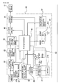
- FIG. 14 is a block diagram showing the control unit of the portable charger for a mobile phone according to the embodiment of the present invention
- the portable charger 1000 for a mobile phone includes a front housing 10 having an accommodation recess 14 formed in the front side of the front housing 10 to accommodate a mobile phone 12, and cutouts 16 formed on the right and left sides of an upper portion of the accommodation recess 14 to allow a user to easily grip the mobile phone 12 seated in the accommodation recess 14 and easily manipulate the volume key (not shown) of the mobile phone 12; a rear housing 20 fastened to the back of the front housing 10 by screws 11 to close the rear open side of the front housing 10; a belt clip 30 detachably attached into a long accommodation recess 22 formed on a back of the rear housing 20 to change the mounting position of the rear housing 20; a fastening unit 40 placed in the long accommodation recess 22 formed on the back of the rear housing 20 to prevent the belt clip 30 from being removed from the accommodation recess 22; a pair of clamps 50 rotatably placed on the right and left sidewalls of the accommodation recess 14
- the belt clip 30 includes a coupling member 31 having a pair of projections 31a formed on the top of the coupling member 31, and a recess 31c formed on the bottom of the coupling member 31 to engage with the projection 42 of the fastening unit 40, so that the coupling member 31, which is placed in the long accommodation recess 22 formed on the back of the rear housing 20, is fastened by the fastening unit 40; a rotating plate 32 having a pair of circular projections 32a and 32b configured to engage with a pair of depressions 31b formed on the circular projection 31d of the coupling member 31, and a coil spring 32d configured to push a catch 32c downward; a fastening member 33 integrated with the circular projection 31d of the coupling member 31 using ultrasonic fusion welding to accommodate the rotating plate 32 so that the rotating plate 32 can be rotated clockwise or counterclockwise; a moving member 34 mounted on the fastening member 33 to be rotated around a hinge pin 33a; and a coil spring 35 configured to push the front end (lower portion in FIG.
- the fastening unit 40 includes a slider 41 configured to be pushed upward by a spring (not shown); a projection 42 integrally formed on the top of the slider 41 to prevent the removal of the belt clip 30 while engaging with the recess 31c formed on the bottom of the coupling member 31 of the belt clip 30; and a projection plate 43 integrally formed on the slider 41 to slide the slider 41 downward to detach the belt clip 30 from the rear housing 10.
- the clamps 50 includes a pair of projections 50c placed on both sidewalls of the accommodation recess 14, formed in the front housing 10, to be selectively projected and retracted and to clamp the mobile phone 12 so as to prevent removal of the mobile phone 12 seated in the accommodation recess 14; a pair of coil springs 51 mounted on shafts 51a; a pair of lower actuating members 52 configured to be pushed inward by the coil spring 51 and protrude the projections 50c when the release button 60 is pulled; and a pair of upper actuating levers 53 mounted on hinge shafts 51a so that, when the release button 60 is pushed, the upper actuating levers 53 come into contact with an inclined surface 64 downwardly formed from the bottom of the release button 60 and are rotated outward, thus retracting the projections 50c.
- the release button 60 is pushed by a coil spring 62 so that the projections 50c of the clamps 50 are pushed toward the accommodation recess 14 formed in the front housing 10.
- the charge control unit 80 includes a microprocessor 81 for controlling an entire operation relating to charge of the battery of the mobile phone 12 and the secondary battery 210; a voltage converting means 82 for receiving the DC power converted by the travel adaptor and the DC power (DC current and DC voltage) charged in the secondary battery 210, boosting or stepping down the DC power to charge the battery of the mobile phone 12, and outputting the boosted or stepped-down DC power to the microprocessor 81; first charging current detecting means 83 for receiving the DC power boosted or stepped-down by the voltage converting means 82, detecting charging current, and outputting the detected charging current to the microprocessor 81; first constant current/voltage adjusting means 84 for receiving the DC voltage boosted or stepped-down by the voltage converting means 82 and the charging current detected by the first charging current detecting means 83, performing operation on the DC voltage and the charging current through the microprocessor 81, and receiving the charging current detected by the first charging current detecting means 83 and adjusting the detected
- the discharge preventing means 90 is composed of a field effect transistor Q5 that operates in such a way as to be switched on by application of low level voltage to a gate terminal through bias resistors R39 and R54 and output the DC power, charged in the secondary battery 210, to the voltage converting means 82 through protection means 211 if the battery of the mobile phone 12 is connected to the positive and negative electrodes of the output terminal 85, and to be switched off by application of high level voltage to a gate terminal through bias resistors R39 and R54 and charge the battery of the mobile terminal 12 if the battery of the mobile phone 12 is not connected to the positive and negative electrodes of the output terminal 85.
- the charge status display means 91 is a dual type light emission diode LED1, and the dual type light emission diode LED1 emits red light to indicate that the secondary battery 210 is being charged if the charge of the battery of the mobile phone 12 is completed, emits green light to indicate that the battery of the mobile phone 12 is being charged if the charge of the secondary battery 210 is completed, and does not emit light to indicate that the battery of the mobile phone 12 and the secondary battery 210 have been charged if the battery of the mobile phone 12 and the secondary battery 210 have been charged.
- R62 and R63 are current limiting resistors.
- the temperature detecting means 92 is a temperature detecting sensor that detects surrounding temperature, and the secondary battery 210 is equipped with the protection means 211 that detects and filters out excessive current and voltage.
- reference numeral 202 is a cord that connects the travel adaptor 200 and the connector 208
- reference numeral 204 is wiring that electrically connects the interface connector 70 with the charge control unit 80.
- the user In order to charge the battery of the mobile phone 12 and the secondary battery 210 seated in the portable charger for a mobile phone 1000 according to the embodiment of the present invention, the user, as shown in FIGS. 10 and 11, connects a charge terminal (not shown), which is formed in the lower portion of the mobile phone, to the interface connector 70 while seating the mobile phone 12 into the accommodation recess 14.
- a charge terminal (not shown), which is formed in the lower portion of the mobile phone
- the projections 50c of the clamps 50 are engaged with the recesses formed on both sides of the mobile phone 12, so that the mobile phone 12 is prevented from the portable charger for a mobile phone 1000.
- the lower actuating levers 52 constituting the lower portions of the clamps 50 are rotated counterclockwise around the hinge shafts 50a against the coil springs 51 and the upper actuating levers 53 of the clamps 50 are also rotated around the hinge shafts 50a, so that the mobile phone 12 can be easily fitted into the accommodation recess 14.
- the upper actuating levers 53 and the lower actuating levers 52 are rotated around the hinge shafts 50a clockwise by the elastic force of the coil springs 51.
- the projections 50c of the clamps 50 are engaged with the recesses formed on both sides of the mobile phone 12, so that the mobile phone 12 is firmly secured in the portable charger for a mobile phone 1000.
- the connector 208 attached to one end of the cord 202 is electrically connected to the charging connector (not shown) mounted in the portable charger for a mobile phone 1000, and then the plug 200a of the travel adaptor 200 attached to the other end of the cord 202 is connected to a 110 or 220 Vac outlet, the travel adaptor 200 receives 110 or 220 Vac, converts the received power into DC voltage and supplies the DC voltage to the charge control unit 80.
- the battery of the mobile phone 12 and the secondary battery 210 are charged with the DC voltage under the control of the charge control unit 80, so that a dual type Light Emitting Diode (LED) LED1 emits orange light.
- LED Light Emitting Diode
- the dual type LED LED1 emits red light, thus indicating that the secondary battery 210 is being charged. If the secondary battery 210 has been charged during charging first, the dual type LED LED1 emits green light, thus indicating that the battery of the mobile phone 12 is being charged. If both of the battery of the mobile phone 12 and the secondary battery 210 have been charged, the dual type LED LED1 does not emit light, thus indicating that both of the battery of the mobile phone 12 and the secondary battery 210 have been charged.
- the projections 50c of the clamps 50 are retracted by pushing the release button 60 of the portable charger for a mobile phone, so that the user can make calls while carrying the mobile phone 12 separated from the portable charger for a mobile phone 1000.
- FIG. 12 An operation of retracting the projections 50c of the clamps 50 is illustrated in FIG. 12.
- the release button 12 When the release button 12 is pushed, the release button 12 is lowered while pushing the coil springs 62. Accordingly, the inclined surface 64 formed on the lower part of the release button 60 rotates the upper actuating levers 53 of the clamps 50 around the hinge shafts 50a counterclockwise, so that the lower actuating levers 52 are rotated around the shafts 51a counterclockwise against the elastic force of the coil springs 51.
- the projections 50c of the clamps 50 are inserted into the front housing 10, so that the mobile phone 12 can be easily separated from the portable charger for a mobile phone 1000.
- the moving member 3 When the lower portion of the moving member 34 is taken away from the fastening member 33 by pushing the moving member 34 of the belt clip 30, the moving member 3 is released from being pushed while the waist belt (not shown) remains positioned between the fastening member 33 and the moving member 34. Accordingly, the moving member 34 clamps the waist belt due to the elastic force of the coil springs 35, so that the belt clip 30 is fastened to the waist belt.
- the rotating plate 32 of the belt clip 30 is rotated in the accommodating recess (not shown), which is formed in the fastening member 33, by rotating the portable charger for a mobile phone 1000 a specific angle (for example, 30° or 90°) clockwise or counterclockwise.
- the catch 32c placed on the rotating plate 32 of the belt clip 30 is rotated while pushing the coil spring 32d, and the front end of the catch 32c is fitted into the recess 33b formed in the inside wall of the accommodation recess of the fastening member 33.
- the catch 32c can be rotated by 90° clockwise or counterclockwise. Accordingly, the assembly of the front housing 10 and the rear housing 20 of the portable charger for a mobile phone 1000 according to the embodiment of the present invention can be located along the length of the waist belt, so that the portable charger for a mobile phone 1000 is easy to carry.
- the mobile phone 12 When the battery of the mobile phone 12 is discharged after the use of the mobile phone 12, and the secondary battery 210 is discharged after charging the battery of the mobile phone 12 with the DC power charged in the secondary battery 210, the mobile phone 12 is seated in the accommodation recess 14 formed in the front housing 10 of the portable charger for a mobile phone 1000.
- the charging terminal (not shown) formed on the lower portion of the mobile phone 12 is connected to the interface connector 70, the connector 208 placed on one side of the cord 202 is electrically connected to the charging connector (not shown) placed in the portable charger for a mobile phone 1000, and the plug 200a of the travel adaptor 200 placed on the other end of the cord 202 is connected to the 110 or 220 Vac outlet, so that the battery of the mobile phone 12 and the secondary battery 210 are charged under the control of the charge control unit 80.
- the DC power obtained by the travel adaptor 200 is boosted or stepped-down by the voltage converting means 82, and the boosted or stepped-down DC power is output both to the microprocessor 81 and to the first charging current detecting means 83.
- the first charging current detecting means 83 receives the DC current boosted or stepped-down by the voltage converting means 82, detects charging current, and outputs the detected charging current both to the microprocessor 81 and to the first constant current/voltage adjusting means 84.
- the microprocessor 81 receives the DC voltage boosted or stepped-down by the voltage converting means 82 and the charging current detected by the first charging current detecting means 83, and performs operation on the DC voltage and the charging current.
- the microprocessor 81 If the DC voltage and the charging current are not constant voltage and current of a predetermined level that is required for the charge of the battery of the mobile phone 12, the microprocessor 81 outputs a control signal to the first constant current/voltage adjusting means 84, and the first constant current/voltage adjusting means 84 adjusts the DC voltage and the charging current to constant voltage and current of a predetermined level required for the charge of the battery of the mobile phone 12 and outputs the adjusted current and voltage to the first switch 86.
- the first switch 86 receives a control signal, which instructs the first switch 86 to charge the battery of the mobile phone 12, from the microprocessor 81, is switched on, and then charges the battery of the mobile phone 12 through the positive and negative electrodes of the output terminal 85.
- the second charging current detecting means 87 receives the DC power obtained by the travel adaptor 200, detects charging current, and outputs the charging current both to the microprocessor 81 and to the second constant current/voltage adjusting means 88.
- the microprocessor 81 receives the charging current detected by the second charging current detecting means 87 and performs operation on the charging current. If the charging current is not constant current and voltage of a predetermined level that is required for the charge of the secondary battery 210, the microprocessor 81 outputs a constant current/voltage adjusting control signal to the second constant current/voltage adjusting means 88.
- the second constant current/voltage adjusting means 88 adjusts the charging current to the constant current and voltage of a predetermined level that is required for the charge of the secondary battery 210, and outputs the constant current and voltage to the second switch 89.
- the second switch 89 is switched on in response to the control signal from the microprocessor 81, and charges the secondary battery 210 with the constant voltage and current adjusted by the second constant current/voltage adjusting means 87, with excessive voltage and current being detected and filtered out by the protection means 211 mounted in the secondary battery 210.
- the mobile phone 12 In order to charge the battery of the mobile phone 12 with the DC power charged in the secondary battery 210 when the battery of the mobile phone 12 is discharged after the user of the mobile phone 12, the mobile phone 12 is seated in the accommodation recess 14 of the front housing 10.
- the voltage converting means 82 receives the DC power charged in the secondary battery 210 through the protecting means 211 and the discharge preventing means 90, boosts or steps down the DC voltage to charge the battery of the mobile phone 12, and outputs the boosted or stepped-down DC voltage both to the microprocessor 81 and to the first charging current detecting means 83.
- the charging current detected by the first charging current detecting means 83 is output both to the microprocessor 81 and to the first constant current/voltage adjusting means 84.
- the microprocessor 81 receives the DC voltage boosted or stepped-down by the voltage converting means 82 and the charging current detected by the first charging current detecting means 83, and performs operation on the boosted or stepped-down voltage and the charging current.
- the microprocessor 81 If the boosted or stepped-down voltage and the charging current are not constant voltage or current of a predetermined level that is required for the charge of the battery of the mobile phone 12, the microprocessor 81 outputs a constant current/voltage control signal to the first constant current/voltage adjusting means 84, and the first constant current/voltage adjusting means 84 adjusts the boosted or stepped-down voltage and the charging current to constant current and voltage of a predetermined level that is required for the charge of the battery of the mobile phone 12, and outputs the adjusted voltage and current to the first switch 86.
- the first switch 86 receives a control signal, which instructs the first switch 86 to charge the battery of the mobile phone 12, from the microprocessor 81, is switched on, and charges the battery of the mobile phone 12 through the positive and negative electrodes of the output terminal 85.
- FIG. 15 is a view showing the portable charger for a mobile phone 1000 that is being charged while remaining combined with a hands-free kit for an automobile.
- FIG. 16 is a view showing the portable charger for a mobile phone 1000 that is being charged while remaining mounted on a table charging stand.
- the mobile phone 12 is seated in the accommodation recess 14 by pushing the mobile phone 12 into the accommodation recess 14 formed in the front of the front housing 10.
- the hands-free kit 220 or the table charging stand 230 is connected to the charging connector of the portable charger for a mobile phone 1000, and the hands-free kit 220 or the plug 228 of the table charging stand 230 is connected to an automobile battery or 110 or 220 Vac outlet, the battery of the mobile phone 12 or the secondary battery 210 contained in the portable charger for a mobile phone according to an embodiment of the present invention is charged.
- the projection plate 43 integrated with the slider 41 of the fastening unit 40 is pushed downward.
- the slider 41 of the fastening member 40 is pushed downward while compressing a spring (not shown), and then the projection 42 integrated with the front end of the slider 41 is removed from the recess 31c formed in the lower portion of the coupling member 31 of the belt clip 30.
- the portable charger for a mobile phone 1000 can be worn on a waist belt using the belt clip, the wearing position of the portable charger for a mobile phone 1000 can be changed through the rotation thereof in the case of being worn on a waist belt, the secondary battery 210 and the battery of the mobile phone 12 can be charged with the DC power obtained by the travel adaptor 200 at the same time, and the charging power of the secondary battery 210 can be prevented from be discharged by turning off the discharge preventing means 90 in the case where the mobile phone 12 is not electrically connected to the accommodation recess 14 of the front housing 10 of the portable charger for a mobile phone 1000.
- charge can be prevented in the case where the surrounding temperature is equal to or higher than a predetermined temperature (about 45°C) or lower than a predetermined temperature (about -5°C), the battery of the mobile phone can be charged with the DC power charged in the secondary battery 210 in a temperature range of about -5°C to 45°C, the portable charger for a mobile phone 1000 can easily charge the battery of the mobile phone 12 using the automobile battery while connecting to the hands-free kit 220, and the portable charger for a mobile phone 1000 can simultaneously charge the secondary battery 210 and the battery of the mobile phone 12 while electrically connecting to the table charging stand 230.
- the present invention is not limited to this case, but the portable charger for a mobile phone may be worn on the edge of a jacket or edge of a pocket of a trouser.
- the present invention is not limited to this case, but only the battery may be seated in the accommodation recess 14 and be charged with power.
- the portable charger for a mobile phone can be easily worn on a waist belt using the belt clip, the wearing position of the portable charger for a mobile phone can be changed through the rotation thereof in the case of being worn on a waist belt, the secondary battery and the battery of the mobile phone can be charged with the DC power obtained by the travel adaptor at the same time, the charging power of the secondary battery can be prevented from being discharged by turning off the discharge preventing means in the case where the mobile phone is not electrically connected to the accommodation recess of the front housing of the portable charger for a mobile phone, charge can be prevented in the case where the surrounding temperature is equal to or higher than a predetermined temperature (about 45°C) or lower than a predetermined temperature (about -5°C), the battery of the mobile phone can be easily charged with the DC voltage charged in the secondary battery, the portable charger for a mobile phone can easily charge the battery of the mobile phone using the automobile battery while connecting to the hands-free kit, and the portable charger for a mobile phone can simultaneously charge the secondary battery
Landscapes
- Chemical & Material Sciences (AREA)
- Chemical Kinetics & Catalysis (AREA)
- Electrochemistry (AREA)
- General Chemical & Material Sciences (AREA)
- Engineering & Computer Science (AREA)
- Power Engineering (AREA)
- Life Sciences & Earth Sciences (AREA)
- Biophysics (AREA)
- Computer Hardware Design (AREA)
- Charge And Discharge Circuits For Batteries Or The Like (AREA)
- Telephone Set Structure (AREA)
Abstract
Description
Claims (9)
- A portable charger for a mobile phone, comprising:a front housing having an accommodation recess formed in a front side of the front housing to accommodate a mobile phone, and cutouts formed on right and left sides of an upper portion of the accommodation recess to allow a user to easily grip the mobile phone seated in the accommodation recess and easily manipulate a volume key of the mobile phone;a rear housing fastened to a back of the front housing by screws to close a rear open side of the front housing;a belt clip detachably attached into a long accommodation recess formed on a back of the rear housing to change a mounting position of the rear housing;a fastening unit placed in the long accommodation recess formed on the back of the rear housing to prevent the belt clip from being removed from the accommodation recess;a pair of clamps rotatably placed on right and left sidewalls of the accommodation recess formed in the front housing to prevent the mobile phone from being removed during charging while engaging with recesses formed on both sides of the mobile phone, respectively;a release button placed above a location between the front housing and the rear housing to regulate protrusion and retraction of projections of the clamps;an interface connector mounted in a lower portion of the accommodation recess, formed in the front housing, through a shaft and a coil spring to be rotated in a block;a secondary battery placed in a space formed by the front and rear housings; anda charge control unit configured to perform control so that Direct Current (DC) voltage, converted by a travel adaptor, is received through a cord and a connector and the second battery and the battery of the mobile phone are simultaneously charged with the DC voltage, or the battery of the mobile phone is charged with DC voltage charged in the secondary battery.
- The portable charger for a mobile phone as set forth in claim 1, wherein the belt clip comprises:a coupling member having a pair of projections formed on a top of the coupling member, and a recess formed on a bottom of the coupling member to engage with a projection of the fastening unit, so that the coupling member, which is placed in the long accommodation recess formed on the back of the rear housing, is fastened by the fastening unit;a rotating plate having a pair of circular projections configured to engage with a pair of depressions formed on a circular projection of the coupling member, and a coil spring configured to push a catch downward;a fastening member integrated with the circular projection of the coupling member using ultrasonic fusion welding to accommodate the rotating plate so that the rotating plate can be rotated clockwise or counterclockwise;a moving member mounted on the fastening member to be rotated around a hinge pin; anda coil spring configured to push a low portion of the moving member to a lower portion of the fastening member.
- The portable charger for a mobile phone as set forth in claim 1, wherein the fastening unit comprises:a slider configured to be pushed upward by a spring;a projection integrally formed on a top of the slider to prevent removal of the belt clip while engaging with the recess formed on the bottom of the coupling member of the belt clip; anda projection plate integrally formed on the slider to slide the slider downward to detach the belt clip from the rear housing.
- The portable charger for a mobile phone as set forth in claim 1, wherein the clamps comprise:a pair of projections placed on both sidewalls of the accommodation recess, formed in the front housing, to be selectively projected and retracted and to clamp the mobile phone so as to prevent removal of the mobile phone seated in the accommodation recess;a pair of coil springs mounted on shafts;a pair of lower actuating members configured to be pushed inward by the coil spring and protrude the projections when the release button is pulled; anda pair of upper actuating levers mounted on hinge shafts so that, when the release button is pushed, the upper actuating levers come into contact with an inclined surface downwardly formed from the bottom of the release button and are rotated outward, thus retracting the projections.
- The portable charger for a mobile phone as set forth in claim 1, wherein the release button is pushed by a coil spring so that the projections of the clamps are pushed toward the accommodation recess formed in the front housing.
- The portable charger for a mobile phone as set forth in claim 1, wherein the charge control unit comprises:a microprocessor for controlling an entire operation relating to charge of the battery of the mobile phone and the secondary battery;voltage converting means for receiving the DC power converted by the travel adaptor and the DC power (DC current and DC voltage) charged in the secondary battery, boosting or stepping down the DC power to charge the battery of the mobile phone, and outputting the boosted or stepped-down DC power to the microprocessor;first charging current detecting means for receiving the DC power boosted or stepped-down by the voltage converting means, detecting charging current, and outputting the detected charging current to the microprocessor;first constant current/voltage adjusting means for receiving the DC voltage boosted or stepped-down by the voltage converting means and the charging current detected by the first charging current detecting means, performing operation on the DC voltage and the charging current through the microprocessor, and receiving the charging current detected by the first charging current detecting means and adjusting the detected charging current to constant current and voltage in response to a control signal from the microprocessor if the boosted or stepped-down voltage and the charging current are not constant current and voltage of a predetermined level;a first switch for receiving the constant current/voltage adjusted by the first constant current/voltage adjusting means and controlling charge of the battery of the mobile phone through an output terminal in response to a control signal from the microprocessor;second charging current detecting means for receiving the DC power (DC current and DC voltage) converted by the travel adaptor, and detecting charging current and outputting the detected charging current to the microprocessor to charge the secondary battery;second constant current/voltage adjusting means for receiving the charging current detected by the second charging current detecting means, performing operation on the charging current through the microprocessor, and receiving the charging current detected by the second charging current detecting means and adjusting the detected charging current to constant current and voltage in response to a control signal from the microprocessor if the charging current is not constant current and voltage of a predetermined level;a second switch for receiving the constant current/voltage adjusted by the second constant current/voltage adjusting means and controlling the charge of the secondary battery in response to a control signal from the microprocessor;discharge preventing means for performing control in such a way as to prevent the DC voltage charged in the secondary battery if the battery of the mobile phone is not connected to the output terminal, and to output the DC power charged in the secondary battery to the voltage converting means and charge the battery of the mobile phone if the battery of the mobile phone is connected to the output terminal;charge status display means for displaying charge status of the battery of the mobile phone and charge status of the secondary battery; andtemperature detecting means for detecting surrounding temperature and outputting the surrounding temperature to the microprocessor to prevent charge of the battery of the mobile phone and the secondary battery under control of the microprocessor if the surrounding temperature is above a predetermined temperature of about 45°C or below a predetermined temperature of about -5°C.
- The portable charger for a mobile phone as set forth in claim 6, wherein the discharge preventing means is composed of a field effect transistor that operates in such a way as to be switched on by application of low level voltage to a gate terminal through bias resistors and output the DC power, charged in the secondary battery, to the voltage converting means through protection means if the battery of the mobile phone is connected to positive and negative electrodes of the output terminal, and to be switched off by application of high level voltage to a gate terminal through bias resistors and charge the battery of the mobile terminal if the battery of the mobile phone is not connected to the positive and negative electrodes of the output terminal.
- The portable charger for a mobile phone as set forth in claim 6, wherein the charge status display means is a dual type light emission diode, and the dual type light emission diode emits red light to indicate that the secondary battery is being charged if the charge of the battery of the mobile phone is completed, emits green light to indicate that the battery of the mobile phone is being charged if the charge of the secondary battery is completed, and does not emit light to indicate that the battery of the mobile phone and the secondary battery have been charged if the battery of the mobile phone and the secondary battery have been charged.
- A portable charger for a mobile phone, comprising:a front housing having an accommodation recess formed in a front side of the front housing to accommodate a mobile phone, and cutouts formed on right and left sides of an upper portion of the accommodation recess to allow a user to easily grip the mobile phone seated in the accommodation recess and easily manipulate a volume key of the mobile phone;a rear housing fastened to a back of the front housing by screws to close a rear open side of the front housing;a belt clip detachably attached into a long accommodation recess formed on a back of the rear housing to change a mounting position of the rear housing;a fastening unit placed in the long accommodation recess formed on the back of the rear housing to prevent the belt clip from being removed from the accommodation recess;a pair of clamps rotatably placed on right and left sidewalls of the accommodation recess formed in the front housing to prevent the mobile phone from being removed during charging while engaging with recesses formed on both sides of the mobile phone, respectively;a release button placed above a location between the front housing and the rear housing to regulate protrusion and retraction of projections of the clamps;an interface connector mounted in a lower portion of the accommodation recess, formed in the front housing, through a shaft and a coil spring to be rotated in a block; anda secondary battery placed in a space formed by the front and rear housings to be charged with DC voltage, obtained by a travel adaptor, under control of a charge control unit.
Applications Claiming Priority (4)
| Application Number | Priority Date | Filing Date | Title |
|---|---|---|---|
| KR2003070665 | 2003-10-10 | ||
| KR1020030070666A KR100414680B1 (en) | 2003-10-10 | 2003-10-10 | Portable charger of mobile phone |
| KR10-2003-0070665A KR100432172B1 (en) | 2003-10-10 | 2003-10-10 | Portable charger of mobile phone |
| KR2003070666 | 2003-10-10 |
Publications (2)
| Publication Number | Publication Date |
|---|---|
| EP1523081A2 true EP1523081A2 (en) | 2005-04-13 |
| EP1523081A3 EP1523081A3 (en) | 2005-06-15 |
Family
ID=34315821
Family Applications (1)
| Application Number | Title | Priority Date | Filing Date |
|---|---|---|---|
| EP04023902A Withdrawn EP1523081A3 (en) | 2003-10-10 | 2004-10-07 | Portable charger for mobile phones |
Country Status (3)
| Country | Link |
|---|---|
| US (1) | US7166987B2 (en) |
| EP (1) | EP1523081A3 (en) |
| CN (1) | CN1612406A (en) |
Cited By (11)
| Publication number | Priority date | Publication date | Assignee | Title |
|---|---|---|---|---|
| EP1675271A1 (en) * | 2004-12-24 | 2006-06-28 | KIM, Dong-Joo | Method for assembling a clip of a case for a mobile phone and connecting structure of the clip |
| WO2007035103A1 (en) * | 2005-09-19 | 2007-03-29 | Jumpit Manufacturing As | Rechargeable back-up battery device |
| WO2007086673A1 (en) * | 2006-01-26 | 2007-08-02 | Ivolta, Inc. | Charging system for mobile devices |
| WO2007100613A3 (en) * | 2006-02-23 | 2007-12-06 | Eveready Battery Inc | Power supply for battery powered devices |
| US7489105B2 (en) | 2005-03-21 | 2009-02-10 | Eveready Battery Company, Inc. | Portable power supply |
| FR2950750A1 (en) * | 2009-09-30 | 2011-04-01 | St Ericsson Grenoble Sas | POWER SUPPLY DEVICE FOR PORTABLE TELECOMMUNICATION EQUIPMENT, AND PORTABLE EQUIPMENT USING SUCH A DEVICE |
| US8343670B2 (en) | 2007-01-25 | 2013-01-01 | Eveready Battery Company, Inc. | Use extender device |
| DE102017103435A1 (en) | 2017-02-20 | 2018-08-23 | Jörg Hupe | Holding device for a mobile terminal and computer program therefor |
| WO2018154263A1 (en) * | 2017-02-21 | 2018-08-30 | PALA, Kishen | Apparatus for holding an e-cigarette |
| EP2841120B1 (en) * | 2012-04-26 | 2020-11-18 | Paul Hartmann AG | Fixing device for a negative pressure therapy apparatus |
| US12341368B1 (en) * | 2020-12-31 | 2025-06-24 | John C. Reding | Cordless power tools battery adapter |
Families Citing this family (219)
| Publication number | Priority date | Publication date | Assignee | Title |
|---|---|---|---|---|
| US6658091B1 (en) | 2002-02-01 | 2003-12-02 | @Security Broadband Corp. | LIfestyle multimedia security system |
| JP2004312538A (en) * | 2003-04-09 | 2004-11-04 | Mitsubishi Electric Corp | Wireless device connection system |
| US9531593B2 (en) | 2007-06-12 | 2016-12-27 | Icontrol Networks, Inc. | Takeover processes in security network integrated with premise security system |
| US10200504B2 (en) | 2007-06-12 | 2019-02-05 | Icontrol Networks, Inc. | Communication protocols over internet protocol (IP) networks |
| US9191228B2 (en) | 2005-03-16 | 2015-11-17 | Icontrol Networks, Inc. | Cross-client sensor user interface in an integrated security network |
| US11277465B2 (en) | 2004-03-16 | 2022-03-15 | Icontrol Networks, Inc. | Generating risk profile using data of home monitoring and security system |
| US11159484B2 (en) | 2004-03-16 | 2021-10-26 | Icontrol Networks, Inc. | Forming a security network including integrated security system components and network devices |
| US9729342B2 (en) | 2010-12-20 | 2017-08-08 | Icontrol Networks, Inc. | Defining and implementing sensor triggered response rules |
| JP2007529826A (en) | 2004-03-16 | 2007-10-25 | アイコントロール ネットワークス, インコーポレイテッド | Object management network |
| US10339791B2 (en) | 2007-06-12 | 2019-07-02 | Icontrol Networks, Inc. | Security network integrated with premise security system |
| US9609003B1 (en) | 2007-06-12 | 2017-03-28 | Icontrol Networks, Inc. | Generating risk profile using data of home monitoring and security system |
| US10382452B1 (en) | 2007-06-12 | 2019-08-13 | Icontrol Networks, Inc. | Communication protocols in integrated systems |
| US8635350B2 (en) | 2006-06-12 | 2014-01-21 | Icontrol Networks, Inc. | IP device discovery systems and methods |
| US20160065414A1 (en) | 2013-06-27 | 2016-03-03 | Ken Sundermeyer | Control system user interface |
| US11190578B2 (en) | 2008-08-11 | 2021-11-30 | Icontrol Networks, Inc. | Integrated cloud system with lightweight gateway for premises automation |
| US10444964B2 (en) | 2007-06-12 | 2019-10-15 | Icontrol Networks, Inc. | Control system user interface |
| US11582065B2 (en) | 2007-06-12 | 2023-02-14 | Icontrol Networks, Inc. | Systems and methods for device communication |
| US8963713B2 (en) | 2005-03-16 | 2015-02-24 | Icontrol Networks, Inc. | Integrated security network with security alarm signaling system |
| US11201755B2 (en) | 2004-03-16 | 2021-12-14 | Icontrol Networks, Inc. | Premises system management using status signal |
| US8988221B2 (en) | 2005-03-16 | 2015-03-24 | Icontrol Networks, Inc. | Integrated security system with parallel processing architecture |
| US10237237B2 (en) | 2007-06-12 | 2019-03-19 | Icontrol Networks, Inc. | Communication protocols in integrated systems |
| US11244545B2 (en) | 2004-03-16 | 2022-02-08 | Icontrol Networks, Inc. | Cross-client sensor user interface in an integrated security network |
| US11916870B2 (en) | 2004-03-16 | 2024-02-27 | Icontrol Networks, Inc. | Gateway registry methods and systems |
| US10142392B2 (en) | 2007-01-24 | 2018-11-27 | Icontrol Networks, Inc. | Methods and systems for improved system performance |
| US11677577B2 (en) | 2004-03-16 | 2023-06-13 | Icontrol Networks, Inc. | Premises system management using status signal |
| US10313303B2 (en) | 2007-06-12 | 2019-06-04 | Icontrol Networks, Inc. | Forming a security network including integrated security system components and network devices |
| US7711796B2 (en) | 2006-06-12 | 2010-05-04 | Icontrol Networks, Inc. | Gateway registry methods and systems |
| US11316958B2 (en) | 2008-08-11 | 2022-04-26 | Icontrol Networks, Inc. | Virtual device systems and methods |
| US11343380B2 (en) | 2004-03-16 | 2022-05-24 | Icontrol Networks, Inc. | Premises system automation |
| US20090077623A1 (en) | 2005-03-16 | 2009-03-19 | Marc Baum | Security Network Integrating Security System and Network Devices |
| US10721087B2 (en) | 2005-03-16 | 2020-07-21 | Icontrol Networks, Inc. | Method for networked touchscreen with integrated interfaces |
| US10522026B2 (en) | 2008-08-11 | 2019-12-31 | Icontrol Networks, Inc. | Automation system user interface with three-dimensional display |
| US11113950B2 (en) | 2005-03-16 | 2021-09-07 | Icontrol Networks, Inc. | Gateway integrated with premises security system |
| US11368429B2 (en) | 2004-03-16 | 2022-06-21 | Icontrol Networks, Inc. | Premises management configuration and control |
| US9141276B2 (en) | 2005-03-16 | 2015-09-22 | Icontrol Networks, Inc. | Integrated interface for mobile device |
| US10375253B2 (en) | 2008-08-25 | 2019-08-06 | Icontrol Networks, Inc. | Security system with networked touchscreen and gateway |
| US12063220B2 (en) | 2004-03-16 | 2024-08-13 | Icontrol Networks, Inc. | Communication protocols in integrated systems |
| US11811845B2 (en) | 2004-03-16 | 2023-11-07 | Icontrol Networks, Inc. | Communication protocols over internet protocol (IP) networks |
| US11489812B2 (en) | 2004-03-16 | 2022-11-01 | Icontrol Networks, Inc. | Forming a security network including integrated security system components and network devices |
| US10156959B2 (en) | 2005-03-16 | 2018-12-18 | Icontrol Networks, Inc. | Cross-client sensor user interface in an integrated security network |
| US11368327B2 (en) | 2008-08-11 | 2022-06-21 | Icontrol Networks, Inc. | Integrated cloud system for premises automation |
| KR20050120874A (en) * | 2004-06-21 | 2005-12-26 | 주식회사 아트랑 | Mobile charger |
| CA2519606A1 (en) * | 2004-09-15 | 2006-03-15 | Belkin Corporation | Power supply system comprising rechargeable battery pack and attachment apparatus |
| US20060145661A1 (en) * | 2004-12-30 | 2006-07-06 | Joseph Patino | System and method for operating a multiple charger |
| US9450776B2 (en) | 2005-03-16 | 2016-09-20 | Icontrol Networks, Inc. | Forming a security network including integrated security system components |
| US11700142B2 (en) | 2005-03-16 | 2023-07-11 | Icontrol Networks, Inc. | Security network integrating security system and network devices |
| US20170180198A1 (en) | 2008-08-11 | 2017-06-22 | Marc Baum | Forming a security network including integrated security system components |
| US11496568B2 (en) | 2005-03-16 | 2022-11-08 | Icontrol Networks, Inc. | Security system with networked touchscreen |
| US11615697B2 (en) | 2005-03-16 | 2023-03-28 | Icontrol Networks, Inc. | Premise management systems and methods |
| US9306809B2 (en) | 2007-06-12 | 2016-04-05 | Icontrol Networks, Inc. | Security system with networked touchscreen |
| US20110128378A1 (en) | 2005-03-16 | 2011-06-02 | Reza Raji | Modular Electronic Display Platform |
| US10999254B2 (en) | 2005-03-16 | 2021-05-04 | Icontrol Networks, Inc. | System for data routing in networks |
| US20120324566A1 (en) | 2005-03-16 | 2012-12-20 | Marc Baum | Takeover Processes In Security Network Integrated With Premise Security System |
| EP1941783A1 (en) * | 2005-10-17 | 2008-07-09 | Widex A/S | Adapter shoe and a combination of adapter shoe and hearing aid |
| DE202006010690U1 (en) * | 2006-01-07 | 2007-03-08 | Rosenboom, Volker Wilhelm | Wireless charging station for mobile phones |
| JP4850518B2 (en) * | 2006-01-18 | 2012-01-11 | 株式会社日立製作所 | Power supply circuit and video display device using the same |
| US8013572B2 (en) * | 2006-04-11 | 2011-09-06 | Andrew Rodgers | Recharging device for use with portable electronic devices |
| US10079839B1 (en) | 2007-06-12 | 2018-09-18 | Icontrol Networks, Inc. | Activation of gateway device |
| US12063221B2 (en) | 2006-06-12 | 2024-08-13 | Icontrol Networks, Inc. | Activation of gateway device |
| WO2008020977A2 (en) * | 2006-08-10 | 2008-02-21 | Conair Corporation | Power cord adaptor for hair appliance |
| JP2008048473A (en) * | 2006-08-10 | 2008-02-28 | Sanyo Electric Co Ltd | Charger |
| US20080061739A1 (en) * | 2006-09-11 | 2008-03-13 | Sheng-Fu Lu | Portable charging device capable of outputting voltage |
| EP2102961A2 (en) | 2006-12-20 | 2009-09-23 | Techtium Ltd. | Battery powered charger |
| US11706279B2 (en) | 2007-01-24 | 2023-07-18 | Icontrol Networks, Inc. | Methods and systems for data communication |
| EP2115848A4 (en) * | 2007-02-14 | 2013-01-23 | Rech Et Dev Everon Ca Inc | System and method for recharging a mobile submersible device |
| US7633385B2 (en) | 2007-02-28 | 2009-12-15 | Ucontrol, Inc. | Method and system for communicating with and controlling an alarm system from a remote server |
| US7619388B1 (en) * | 2007-03-05 | 2009-11-17 | Nana Prince K | Detachable back-up battery pack for cell phone |
| US8451986B2 (en) | 2007-04-23 | 2013-05-28 | Icontrol Networks, Inc. | Method and system for automatically providing alternate network access for telecommunications |
| TWM325668U (en) * | 2007-05-25 | 2008-01-11 | Great Performance Ind Co Ltd | Portable power protection and power supply device |
| US10523689B2 (en) | 2007-06-12 | 2019-12-31 | Icontrol Networks, Inc. | Communication protocols over internet protocol (IP) networks |
| US12184443B2 (en) | 2007-06-12 | 2024-12-31 | Icontrol Networks, Inc. | Controlling data routing among networks |
| US11316753B2 (en) | 2007-06-12 | 2022-04-26 | Icontrol Networks, Inc. | Communication protocols in integrated systems |
| US12283172B2 (en) | 2007-06-12 | 2025-04-22 | Icontrol Networks, Inc. | Communication protocols in integrated systems |
| US10389736B2 (en) | 2007-06-12 | 2019-08-20 | Icontrol Networks, Inc. | Communication protocols in integrated systems |
| US11237714B2 (en) | 2007-06-12 | 2022-02-01 | Control Networks, Inc. | Control system user interface |
| US10666523B2 (en) | 2007-06-12 | 2020-05-26 | Icontrol Networks, Inc. | Communication protocols in integrated systems |
| US10498830B2 (en) | 2007-06-12 | 2019-12-03 | Icontrol Networks, Inc. | Wi-Fi-to-serial encapsulation in systems |
| US11423756B2 (en) | 2007-06-12 | 2022-08-23 | Icontrol Networks, Inc. | Communication protocols in integrated systems |
| US11089122B2 (en) | 2007-06-12 | 2021-08-10 | Icontrol Networks, Inc. | Controlling data routing among networks |
| US10051078B2 (en) | 2007-06-12 | 2018-08-14 | Icontrol Networks, Inc. | WiFi-to-serial encapsulation in systems |
| US11212192B2 (en) | 2007-06-12 | 2021-12-28 | Icontrol Networks, Inc. | Communication protocols in integrated systems |
| US10423309B2 (en) | 2007-06-12 | 2019-09-24 | Icontrol Networks, Inc. | Device integration framework |
| US11646907B2 (en) | 2007-06-12 | 2023-05-09 | Icontrol Networks, Inc. | Communication protocols in integrated systems |
| US11218878B2 (en) | 2007-06-12 | 2022-01-04 | Icontrol Networks, Inc. | Communication protocols in integrated systems |
| US10616075B2 (en) | 2007-06-12 | 2020-04-07 | Icontrol Networks, Inc. | Communication protocols in integrated systems |
| US11601810B2 (en) | 2007-06-12 | 2023-03-07 | Icontrol Networks, Inc. | Communication protocols in integrated systems |
| US12003387B2 (en) | 2012-06-27 | 2024-06-04 | Comcast Cable Communications, Llc | Control system user interface |
| US20080319732A1 (en) * | 2007-06-22 | 2008-12-25 | Farnsworth Jeffrey S | Serial channel emulator |
| EP2009761A1 (en) * | 2007-06-29 | 2008-12-31 | Kapa Reynolds | System with an electric energy consuming device with a built-in rechargeable source and an external energy source |
| US10223903B2 (en) | 2010-09-28 | 2019-03-05 | Icontrol Networks, Inc. | Integrated security system with parallel processing architecture |
| US12541237B2 (en) | 2007-08-10 | 2026-02-03 | Icontrol Networks, Inc. | Integrated security system with parallel processing architecture |
| US11831462B2 (en) | 2007-08-24 | 2023-11-28 | Icontrol Networks, Inc. | Controlling data routing in premises management systems |
| US20090059636A1 (en) * | 2007-08-29 | 2009-03-05 | Cyber Power System Inc. | Power adapter having an electricity storing capability |
| US8026693B2 (en) * | 2007-10-18 | 2011-09-27 | Wi.U, Llc | Induction charger for portable battery-powered devices |
| US20110065497A1 (en) * | 2007-12-04 | 2011-03-17 | Emarker, Llc | System for and method of electronically handling a casino marker |
| US20120049800A1 (en) * | 2010-08-25 | 2012-03-01 | Clevx, Llc | Power supply system with automatic sensing mechanism and method of operation thereof |
| US9300203B2 (en) | 2007-12-10 | 2016-03-29 | Clevx, Llc | Battery power supply with automatic load sensing |
| US8367235B2 (en) | 2008-01-18 | 2013-02-05 | Mophie, Inc. | Battery pack, holster, and extendible processing and interface platform for mobile devices |
| US11916928B2 (en) | 2008-01-24 | 2024-02-27 | Icontrol Networks, Inc. | Communication protocols over internet protocol (IP) networks |
| US20170185278A1 (en) | 2008-08-11 | 2017-06-29 | Icontrol Networks, Inc. | Automation system user interface |
| US11758026B2 (en) | 2008-08-11 | 2023-09-12 | Icontrol Networks, Inc. | Virtual device systems and methods |
| US11792036B2 (en) | 2008-08-11 | 2023-10-17 | Icontrol Networks, Inc. | Mobile premises automation platform |
| US11258625B2 (en) | 2008-08-11 | 2022-02-22 | Icontrol Networks, Inc. | Mobile premises automation platform |
| US11729255B2 (en) | 2008-08-11 | 2023-08-15 | Icontrol Networks, Inc. | Integrated cloud system with lightweight gateway for premises automation |
| WO2010025468A1 (en) * | 2008-08-29 | 2010-03-04 | Icontrol Networks, Inc. | Battery-backed power interface transformer for low-power devices |
| US9628440B2 (en) | 2008-11-12 | 2017-04-18 | Icontrol Networks, Inc. | Takeover processes in security network integrated with premise security system |
| US7782610B2 (en) | 2008-11-17 | 2010-08-24 | Incase Designs Corp. | Portable electronic device case with battery |
| US7612997B1 (en) * | 2008-11-17 | 2009-11-03 | Incase Designs Corp. | Portable electronic device case with battery |
| US8638211B2 (en) | 2009-04-30 | 2014-01-28 | Icontrol Networks, Inc. | Configurable controller and interface for home SMA, phone and multimedia |
| US8467805B2 (en) * | 2009-05-08 | 2013-06-18 | Andrew Llc | System and method for determining a reference location using cell table data mining |
| EP2626958A3 (en) * | 2009-07-10 | 2014-01-08 | BlackBerry Limited | Electrical charger |
| GB2478599B (en) * | 2010-03-12 | 2014-07-16 | Dyson Technology Ltd | A vacuum cleaning arrangement |
| AU2011250886A1 (en) | 2010-05-10 | 2013-01-10 | Icontrol Networks, Inc | Control system user interface |
| WO2011146778A1 (en) | 2010-05-19 | 2011-11-24 | Mophie, Inc. | Electronic wallet accessory for mobile device |
| US8457701B2 (en) | 2010-06-16 | 2013-06-04 | Incase Designs Corp. | Case for portable electronic device |
| US8328008B2 (en) | 2010-08-10 | 2012-12-11 | Incase Designs Corp. | Case for electronic tablet |
| WO2012021128A1 (en) * | 2010-08-10 | 2012-02-16 | Ever Win International Corporation | Efficient power supply/charger |
| US8400109B2 (en) * | 2010-09-15 | 2013-03-19 | Day Sun Industrial Corp. | Flashlight charger |
| US8836467B1 (en) | 2010-09-28 | 2014-09-16 | Icontrol Networks, Inc. | Method, system and apparatus for automated reporting of account and sensor zone information to a central station |
| US11750414B2 (en) | 2010-12-16 | 2023-09-05 | Icontrol Networks, Inc. | Bidirectional security sensor communication for a premises security system |
| US9147337B2 (en) | 2010-12-17 | 2015-09-29 | Icontrol Networks, Inc. | Method and system for logging security event data |
| US8712486B2 (en) * | 2011-01-12 | 2014-04-29 | Yeoshua Sorias | Detachably integrated battery charger for mobile cell phones and like devices |
| TW201236305A (en) * | 2011-02-17 | 2012-09-01 | cheng-jun Zhang | Cable structure with indication function |
| KR101768723B1 (en) * | 2011-03-30 | 2017-08-17 | 삼성전자주식회사 | Method and system for wireless charging in a portable terminal |
| CN102185368A (en) * | 2011-05-12 | 2011-09-14 | 鸿富锦精密工业(深圳)有限公司 | Charger |
| EP2717734A4 (en) | 2011-06-10 | 2015-03-04 | Mophie Inc | WIRELESS COMMUNICATION ACCESSORY FOR MOBILE DEVICE |
| US8929065B2 (en) * | 2011-08-23 | 2015-01-06 | L&P Property Management Company | Docking station with ruggedized case |
| US9130384B2 (en) | 2011-10-06 | 2015-09-08 | Prong, Inc. | Smart phone and/or consumer electronics device charger system |
| USD718289S1 (en) | 2011-11-11 | 2014-11-25 | Mophie, Inc. | Multi-piece case |
| CA2855830A1 (en) * | 2011-11-16 | 2013-05-23 | Volcano Corporation | Medical measuring system and method |
| CA2862472C (en) | 2012-01-03 | 2019-07-16 | Philip Morris Products S.A. | Polygonal aerosol-generating device and system |
| USD711819S1 (en) | 2012-01-09 | 2014-08-26 | Mophie Inc. | Mobile battery charger |
| USD714215S1 (en) | 2012-01-09 | 2014-09-30 | Mophie, Inc. | Mobile battery charger |
| USD723457S1 (en) | 2012-01-11 | 2015-03-03 | Yeoshua Sorias | Phone charger |
| US20130187606A1 (en) * | 2012-01-23 | 2013-07-25 | Shao-Chieh Ting | Charger for a cell phone or tablet personal computer with function of winding a wire |
| US8611075B2 (en) * | 2012-02-06 | 2013-12-17 | Zane Carter | Apparatus for mounting an audio player |
| JP2015506663A (en) * | 2012-02-07 | 2015-03-02 | パック チャージャー システムズ プロプライエタリー リミテッドPuck Charger Systems Pty Ltd. | System and method for charging mobile devices in a venue |
| CN102581825B (en) * | 2012-03-21 | 2014-05-21 | 无锡市新菊电动工具有限公司 | Lithium battery pack interface seat for electric tool |
| CN103368213A (en) * | 2012-03-29 | 2013-10-23 | 富泰华工业(深圳)有限公司 | Charging seat |
| USD720687S1 (en) | 2012-05-24 | 2015-01-06 | Mophie, Inc. | Mobile battery charger |
| USD728467S1 (en) | 2012-05-24 | 2015-05-05 | Mophie, Inc. | Mobile battery charger |
| USD721685S1 (en) | 2012-05-25 | 2015-01-27 | Mophie, Inc. | Mobile phone case |
| USD721356S1 (en) | 2012-05-25 | 2015-01-20 | Mophie, Inc. | Mobile phone case |
| US8988040B2 (en) * | 2012-06-07 | 2015-03-24 | Navajo Manufacturing Company, Inc. | Compact car charger |
| USD676382S1 (en) * | 2012-07-20 | 2013-02-19 | Scosche Industries, Inc. | Home charger |
| USD683310S1 (en) * | 2012-07-20 | 2013-05-28 | Scosche Industries, Inc. | Home charger |
| USD727883S1 (en) | 2012-07-20 | 2015-04-28 | Mophie, Inc. | Mobile phone case |
| KR20140024157A (en) * | 2012-08-20 | 2014-02-28 | 삼성에스디아이 주식회사 | Power supply control device for rechargeabel battery |
| WO2014036248A1 (en) | 2012-09-01 | 2014-03-06 | Mophie, Inc. | Wireless communication accessory for a mobile device |
| US9179558B1 (en) | 2012-09-17 | 2015-11-03 | Brite Case, LLC | Case with panel for display |
| USD723530S1 (en) | 2012-10-03 | 2015-03-03 | Mophie, Inc. | Unbanded battery case for a mobile device |
| USD721687S1 (en) | 2012-10-30 | 2015-01-27 | Mophie, Inc. | High capacity banded battery case for a mobile device |
| USD718754S1 (en) | 2012-10-30 | 2014-12-02 | Mophie, Inc. | Thin banded battery case for a mobile device |
| USD718293S1 (en) | 2012-11-30 | 2014-11-25 | Mophie, Inc. | Unbanded snap battery case for a mobile device |
| USD718230S1 (en) | 2012-12-04 | 2014-11-25 | Mophie, Inc. | High capacity banded snap battery case for a mobile device |
| USD718755S1 (en) | 2012-12-18 | 2014-12-02 | Mophie, Inc. | Thin banded snap battery case for a mobile device |
| US9755444B2 (en) | 2013-02-25 | 2017-09-05 | Mophie, Inc. | Protective case with switch cover |
| US9928975B1 (en) | 2013-03-14 | 2018-03-27 | Icontrol Networks, Inc. | Three-way switch |
| US20140265564A1 (en) * | 2013-03-15 | 2014-09-18 | Third Wave Power Pte Ltd | Solar device with removable cassette |
| US9287727B1 (en) | 2013-03-15 | 2016-03-15 | Icontrol Networks, Inc. | Temporal voltage adaptive lithium battery charger |
| EP2974044A4 (en) | 2013-03-15 | 2016-11-09 | Mophie Inc | Protective case for mobile device |
| US9867143B1 (en) | 2013-03-15 | 2018-01-09 | Icontrol Networks, Inc. | Adaptive Power Modulation |
| USD732012S1 (en) | 2013-04-06 | 2015-06-16 | Mophie, Inc. | Curved battery case for a mobile device |
| CN103263130A (en) * | 2013-05-31 | 2013-08-28 | 苏州原点工业设计有限公司 | Socket type mobile phone protective cover |
| US9413179B2 (en) | 2013-07-09 | 2016-08-09 | Yeoshua Sorias | Detachably integrated battery charger for mobile cell phones and like devices |
| EP3031206B1 (en) | 2013-08-09 | 2020-01-22 | ICN Acquisition, LLC | System, method and apparatus for remote monitoring |
| US11228333B1 (en) * | 2013-08-20 | 2022-01-18 | Conell Harris | Protective cell phone case with retractable tether |
| KR102063209B1 (en) * | 2013-09-16 | 2020-01-07 | 엘지전자 주식회사 | Mobile terminal and method for charging battery of the same |
| TWI518486B (en) * | 2013-11-14 | 2016-01-21 | 仁寶電腦工業股份有限公司 | charger |
| WO2015081125A1 (en) | 2013-11-27 | 2015-06-04 | Mophie, Inc. | Battery pack with supplemental memory |
| USD733043S1 (en) | 2013-12-09 | 2015-06-30 | Mophie, Inc. | Battery pack |
| USD721646S1 (en) | 2014-01-02 | 2015-01-27 | Mophie, Inc. | Battery pack with integrated connector |
| GB2522242A (en) * | 2014-01-20 | 2015-07-22 | Nokia Technologies Oy | Additional battery pack |
| US10084329B2 (en) * | 2014-02-28 | 2018-09-25 | Nrg Energy, Inc. | Power pack vending apparatus, system, and method of use for charging power packs with biased locking arrangement |
| US11405463B2 (en) | 2014-03-03 | 2022-08-02 | Icontrol Networks, Inc. | Media content management |
| US11146637B2 (en) | 2014-03-03 | 2021-10-12 | Icontrol Networks, Inc. | Media content management |
| TWI681691B (en) | 2014-04-30 | 2020-01-01 | 瑞士商菲利浦莫里斯製品股份有限公司 | Electrically heated aerosol-generating system, device and method of controlling the same |
| USD744944S1 (en) * | 2014-06-24 | 2015-12-08 | Deltona Transformer Corporation | Battery charger |
| USD744945S1 (en) * | 2014-06-24 | 2015-12-08 | Deltona Transformer Corporation | Battery charger |
| US10027149B2 (en) | 2014-06-29 | 2018-07-17 | William J. Warren | Electrical charging device chassis and cases |
| US9627802B2 (en) | 2014-06-29 | 2017-04-18 | William J. Warren | Electrical charging devices and assemblies |
| US9620911B2 (en) * | 2014-06-29 | 2017-04-11 | William J. Warren | Electrical charging devices and assemblies |
| US10063088B2 (en) | 2014-06-29 | 2018-08-28 | William J. Warren | Computing device inductive charging cases and methods of use |
| US10153649B2 (en) | 2014-06-29 | 2018-12-11 | William J. Warren | Computing device charging cases and methods of use |
| US9997933B2 (en) | 2014-09-03 | 2018-06-12 | Mophie, Inc. | Systems and methods for battery charging and management |
| US9153985B1 (en) | 2014-09-30 | 2015-10-06 | Mophie, Inc. | Portable charging device |
| USD797091S1 (en) | 2014-11-25 | 2017-09-12 | Mophie, Inc. | Case for a mobile electronic device |
| USD797092S1 (en) | 2014-11-25 | 2017-09-12 | Mophie, Inc. | Case for a mobile electronic device |
| USD797093S1 (en) | 2014-12-03 | 2017-09-12 | Mophie, Inc. | Case for a mobile electronic device |
| US9356267B1 (en) | 2014-12-17 | 2016-05-31 | Mophie, Inc. | Protective battery case to partially enclose a mobile electronic device |
| USD766819S1 (en) | 2015-04-06 | 2016-09-20 | Mophie, Inc. | Protective battery case |
| USD767485S1 (en) | 2015-04-07 | 2016-09-27 | Mophie, Inc. | Battery case |
| US10263450B2 (en) * | 2015-05-13 | 2019-04-16 | Intel IP Corporation | Power regulation in wireless charging |
| USD861653S1 (en) | 2015-05-27 | 2019-10-01 | Mophie Inc. | Protective battery case for mobile communications device |
| USD950538S1 (en) * | 2016-03-03 | 2022-05-03 | Mophie Inc. | Case for a mobile electronic device |
| CN105632378B (en) * | 2016-03-11 | 2022-03-08 | 南京索莱电子科技有限公司 | Convenient intelligent tour guide system charging device |
| US10283975B1 (en) * | 2016-03-28 | 2019-05-07 | Amazon Technologies, Inc. | Smart diagnostics for hot-pluggable battery systems |
| CN206164608U (en) * | 2016-05-10 | 2017-05-10 | 华为技术有限公司 | Panel and terminal of terminal shell, terminal shell |
| USD823244S1 (en) * | 2016-08-23 | 2018-07-17 | Vorbeck Materials Corp. | Charger base |
| US20180229045A1 (en) * | 2017-02-13 | 2018-08-16 | Boston Scientific Neuromodulation Corporation | Charging Coil Holding Device for an Implantable Medical Device with Movable Charging Coil |
| US9997882B1 (en) * | 2017-02-27 | 2018-06-12 | William J. Warren | Electrical charging devices and assemblies |
| US10608449B2 (en) | 2017-02-27 | 2020-03-31 | William J. Warren | Electrical charging devices with translating stabilizers |
| US10608384B2 (en) * | 2017-02-27 | 2020-03-31 | William J. Warren | Electrical charging devices with bar stabilizers and assemblies |
| US10177584B2 (en) | 2017-02-27 | 2019-01-08 | William J. Warren | Electrical charging devices and assemblies |
| USD886733S1 (en) | 2017-04-11 | 2020-06-09 | William J. Warren | Charger |
| CN107215283A (en) * | 2017-05-22 | 2017-09-29 | 成都锐奕信息技术有限公司 | The charger of vehicle-mounted type wireless positioning terminal |
| US10050397B1 (en) * | 2017-06-26 | 2018-08-14 | Daniel Hetzroni | Mount for a touch-screen device |
| CN207304039U (en) * | 2017-07-07 | 2018-05-01 | 深圳市正浩创新科技有限公司 | Mobile power |
| JP2019036827A (en) * | 2017-08-14 | 2019-03-07 | パナソニックIpマネジメント株式会社 | Mobile device |
| US10355501B2 (en) | 2017-10-11 | 2019-07-16 | William J. Warren | Electrical charging devices with resilient actuation |
| US10516431B2 (en) | 2017-11-21 | 2019-12-24 | Mophie Inc. | Mobile device case for receiving wireless signals |
| CN107896455B (en) * | 2017-12-18 | 2024-03-15 | 深圳市宝尔爱迪科技有限公司 | A lock structure and a charger using the structure |
| CN109167420B (en) * | 2018-10-31 | 2020-11-03 | 维沃移动通信有限公司 | A charging control circuit, charging circuit and charging control method |
| CN109614831B (en) * | 2018-10-31 | 2022-08-19 | 国网山东省电力公司烟台供电公司 | Portable on-site general survey code scanning gun |
| USD940647S1 (en) | 2019-01-07 | 2022-01-11 | Mophie Inc. | Battery pack |
| US12444972B2 (en) * | 2021-06-18 | 2025-10-14 | Samsung Electronics Co., Ltd. | Power charging system and power charging method using adapter with built-in battery |
| US12469595B2 (en) | 2022-03-11 | 2025-11-11 | Fujifilm Sonosite, Inc. | Ultrasound utility station |
| US11855397B1 (en) * | 2023-07-20 | 2023-12-26 | Pioneer Square Brands, Inc. | Stand with movable connector interface for portable electronic device |
| US12385594B1 (en) * | 2025-03-10 | 2025-08-12 | Pioneer Square Brands, Inc. | Stand system for portable electronic device |
Family Cites Families (10)
| Publication number | Priority date | Publication date | Assignee | Title |
|---|---|---|---|---|
| US4400848A (en) * | 1980-10-25 | 1983-08-30 | Alfred Grass | Door hinge with a sliding catch |
| US4974432A (en) * | 1989-08-14 | 1990-12-04 | Blake Chien Yung H | Combination lock for use on a zipper |
| GB2293056B (en) * | 1994-09-08 | 1999-08-18 | Nokia Mobile Phones Ltd | A holder for charging a radio telephone battery |
| US5664292A (en) * | 1996-08-22 | 1997-09-09 | E Lead Electronic Co., Ltd. | Separable clip assembly |
| JP3060291B2 (en) * | 1996-10-09 | 2000-07-10 | 松下電器産業株式会社 | Battery pack holding device |
| AU4436999A (en) * | 1998-06-19 | 2000-01-05 | John Moong Hung Tsang | Plug assembly |
| US6184654B1 (en) * | 1998-07-28 | 2001-02-06 | Double-Time Battery Corporation | Wearable docking-holster system, with energy management, to support portable electronic devices |
| FI20000377A7 (en) * | 2000-02-18 | 2001-08-19 | Nokia Corp | Multi-purpose battery charger |
| US6643528B1 (en) * | 2000-09-08 | 2003-11-04 | Mobigence, Inc. | Integrated radiotelephone holster and audio appliance |
| US20040069821A1 (en) * | 2002-10-10 | 2004-04-15 | Masatoshi Kobayashi | Rotating detachable belt clip |
-
2004
- 2004-10-05 US US10/959,011 patent/US7166987B2/en not_active Expired - Fee Related
- 2004-10-07 EP EP04023902A patent/EP1523081A3/en not_active Withdrawn
- 2004-10-10 CN CNA2004100809493A patent/CN1612406A/en active Pending
Cited By (18)
| Publication number | Priority date | Publication date | Assignee | Title |
|---|---|---|---|---|
| EP1675271A1 (en) * | 2004-12-24 | 2006-06-28 | KIM, Dong-Joo | Method for assembling a clip of a case for a mobile phone and connecting structure of the clip |
| US7777449B2 (en) | 2005-03-21 | 2010-08-17 | Eveready Battery Company, Inc. | Power supply that provides an output voltage through an electrical connector |
| US7489105B2 (en) | 2005-03-21 | 2009-02-10 | Eveready Battery Company, Inc. | Portable power supply |
| WO2007035103A1 (en) * | 2005-09-19 | 2007-03-29 | Jumpit Manufacturing As | Rechargeable back-up battery device |
| WO2007086673A1 (en) * | 2006-01-26 | 2007-08-02 | Ivolta, Inc. | Charging system for mobile devices |
| CN101390270B (en) * | 2006-02-23 | 2011-08-10 | 永备电池有限公司 | Power supply for battery powered device |
| US7531986B2 (en) | 2006-02-23 | 2009-05-12 | Eveready Battery Company, Inc. | Power supply for battery powered devices |
| WO2007100613A3 (en) * | 2006-02-23 | 2007-12-06 | Eveready Battery Inc | Power supply for battery powered devices |
| US8022662B2 (en) | 2006-02-23 | 2011-09-20 | Eveready Battery Company, Inc. | Power supply for battery powered devices |
| US8686682B2 (en) | 2006-02-23 | 2014-04-01 | Eveready Battery Company, Inc. | Power supply for battery powered devices |
| EP3249772A1 (en) * | 2006-02-23 | 2017-11-29 | Energizer Brands, LLC | Power supply for battery powered devices |
| US8343670B2 (en) | 2007-01-25 | 2013-01-01 | Eveready Battery Company, Inc. | Use extender device |
| FR2950750A1 (en) * | 2009-09-30 | 2011-04-01 | St Ericsson Grenoble Sas | POWER SUPPLY DEVICE FOR PORTABLE TELECOMMUNICATION EQUIPMENT, AND PORTABLE EQUIPMENT USING SUCH A DEVICE |
| WO2011039326A3 (en) * | 2009-09-30 | 2011-11-17 | St-Ericsson (Grenoble) Sas | Device for supplying electric power to a mobile telecommunication equipment, and portable equipment using the same |
| EP2841120B1 (en) * | 2012-04-26 | 2020-11-18 | Paul Hartmann AG | Fixing device for a negative pressure therapy apparatus |
| DE102017103435A1 (en) | 2017-02-20 | 2018-08-23 | Jörg Hupe | Holding device for a mobile terminal and computer program therefor |
| WO2018154263A1 (en) * | 2017-02-21 | 2018-08-30 | PALA, Kishen | Apparatus for holding an e-cigarette |
| US12341368B1 (en) * | 2020-12-31 | 2025-06-24 | John C. Reding | Cordless power tools battery adapter |
Also Published As
| Publication number | Publication date |
|---|---|
| US20050088141A1 (en) | 2005-04-28 |
| US7166987B2 (en) | 2007-01-23 |
| CN1612406A (en) | 2005-05-04 |
| EP1523081A3 (en) | 2005-06-15 |
Similar Documents
| Publication | Publication Date | Title |
|---|---|---|
| US7166987B2 (en) | Portable charger for mobile phone | |
| US6243276B1 (en) | Power supply system for battery operated devices | |
| EP0401531B1 (en) | Battery powered vacuum cleaner | |
| CN103415977B (en) | Removable integrated battery chargers for mobile phones and similar devices | |
| CN103718421B (en) | Charger for a hand-held power tool, electric tool system and the method that power tool battery is charged | |
| US7151356B1 (en) | Retractable cord power adapter and battery pack | |
| CN1767258B (en) | battery charger | |
| US5122721A (en) | Combination battery charger and ac adapter | |
| US20080174269A1 (en) | Battery charger with charge indicator | |
| WO2007143007A2 (en) | Recharging power source with lighting accessory | |
| US6966669B2 (en) | Utility light | |
| US6268709B1 (en) | Charging device for a cellular phone | |
| CN217607501U (en) | Charger adapted to charge either of first battery pack and second battery pack, and kit | |
| GB2344229A (en) | Battery charger | |
| US20020171396A1 (en) | Rechargeable remote control | |
| KR100414680B1 (en) | Portable charger of mobile phone | |
| US20240204329A1 (en) | Bike Derailleur Battery Case with Bi-directional Charging/Discharging USB C Power Delivery (PD) Converter | |
| JP3992119B2 (en) | Charger | |
| US20210184277A1 (en) | Battery pack system with integrated charging device | |
| US20040051388A1 (en) | Power tool with replaceable power supply cartridge | |
| GB2313242A (en) | Charging portable telephone batteries | |
| KR100449650B1 (en) | Charge control method of portable charger for mobile phone | |
| JP3796506B2 (en) | Charger for mobile phone | |
| KR200377878Y1 (en) | Portable charger which has standard USB interface and battery display | |
| KR100432172B1 (en) | Portable charger of mobile phone |
Legal Events
| Date | Code | Title | Description |
|---|---|---|---|
| PUAI | Public reference made under article 153(3) epc to a published international application that has entered the european phase |
Free format text: ORIGINAL CODE: 0009012 |
|
| AK | Designated contracting states |
Kind code of ref document: A2 Designated state(s): AT BE BG CH CY CZ DE DK EE ES FI FR GB GR HU IE IT LI LU MC NL PL PT RO SE SI SK TR |
|
| AX | Request for extension of the european patent |
Extension state: AL HR LT LV MK |
|
| PUAL | Search report despatched |
Free format text: ORIGINAL CODE: 0009013 |
|
| AK | Designated contracting states |
Kind code of ref document: A3 Designated state(s): AT BE BG CH CY CZ DE DK EE ES FI FR GB GR HU IE IT LI LU MC NL PL PT RO SE SI SK TR |
|
| AX | Request for extension of the european patent |
Extension state: AL HR LT LV MK |
|
| 17P | Request for examination filed |
Effective date: 20051207 |
|
| AKX | Designation fees paid |
Designated state(s): DE FR GB IT NL |
|
| 17Q | First examination report despatched |
Effective date: 20061019 |
|
| STAA | Information on the status of an ep patent application or granted ep patent |
Free format text: STATUS: THE APPLICATION IS DEEMED TO BE WITHDRAWN |
|
| 18D | Application deemed to be withdrawn |
Effective date: 20100504 |