EP1523085A2 - Machine électrique fermée et méthode de dimensionnement d'une telle machine - Google Patents
Machine électrique fermée et méthode de dimensionnement d'une telle machine Download PDFInfo
- Publication number
- EP1523085A2 EP1523085A2 EP04450187A EP04450187A EP1523085A2 EP 1523085 A2 EP1523085 A2 EP 1523085A2 EP 04450187 A EP04450187 A EP 04450187A EP 04450187 A EP04450187 A EP 04450187A EP 1523085 A2 EP1523085 A2 EP 1523085A2
- Authority
- EP
- European Patent Office
- Prior art keywords
- machine
- cooling fins
- nodes
- housing
- electrical machine
- Prior art date
- Legal status (The legal status is an assumption and is not a legal conclusion. Google has not performed a legal analysis and makes no representation as to the accuracy of the status listed.)
- Withdrawn
Links
Images


Classifications
-
- H—ELECTRICITY
- H02—GENERATION; CONVERSION OR DISTRIBUTION OF ELECTRIC POWER
- H02K—DYNAMO-ELECTRIC MACHINES
- H02K5/00—Casings; Enclosures; Supports
- H02K5/04—Casings or enclosures characterised by the shape, form or construction thereof
- H02K5/18—Casings or enclosures characterised by the shape, form or construction thereof with ribs or fins for improving heat transfer
-
- H—ELECTRICITY
- H02—GENERATION; CONVERSION OR DISTRIBUTION OF ELECTRIC POWER
- H02K—DYNAMO-ELECTRIC MACHINES
- H02K5/00—Casings; Enclosures; Supports
- H02K5/04—Casings or enclosures characterised by the shape, form or construction thereof
- H02K5/06—Cast metal casings
Definitions
- the invention relates to an encapsulated electrical machine, preferably vertically installed asynchronous traction machine, with a housing, a stator arranged in the housing and a rotating one Shaft with a rotor attached to it, the machine optionally for assembly with a gearbox is provided, wherein the bearing takes place on the transmission side.
- Electric motors for driving vehicles must be as close as possible be possible on the driven axle to complicated and expensive To bypass power transmissions.
- the tons heavier Rail vehicles can only drive the electric drive motors directly be arranged in the bogie. At every turn and even when driving straight ahead, there are large relative movements between the bogie and car body, the power transmission in an arrangement the drive motor outside the bogie constantly would have to compensate.
- the bogie is but directly above the rails or over the floor.
- the usual fürzugsbel hereeten motors can therefore through the wind very easily foreign objects, such as pebbles, Dust or rain water with the cooling air into the engine and damage it, leaving it prematurely after a short operating time fails. That is why rail vehicles are almost exclusive closed or encapsulated motors are used.
- the bogie also houses the suspension and brakes, so that there is hardly enough space for the drive motors is.
- the object of the invention is therefore to provide a machine of the aforementioned Kind of creating, on the one hand, the above disadvantages avoids and on the other hand constructively the given space conditions can be adjusted in the driven vehicle.
- Another object of the present invention is the Creation of a method for the interpretation of one of the above electrical machine through which the real conditions in the Operation of the electric machine can be considered and thus the machine optimally adapted to the respective application can be.
- the first electrical machine according to the invention is characterized that the dissipation of heat loss through natural convection or radiation and optionally by one of the airstream produced convection, wherein the housing made of light metal, preferably aluminum, is made and the housing outside, diagonally opposite, cooling fins has.
- the cooling fins are arranged so that the existing space is used optimally.
- the necessary for cooling Surface of the cooling fins to be arranged is about one, later calculated, computation or data processing program calculated.
- the calculated and required for cooling surface can then be transferred to the number and dimensions of the cooling fins.
- the cooling fins can then be structurally arranged so that on the one hand the calculated surface is reached and on the other hand the installation conditions is taken into account.
- Another advantage of this enclosed machine is to be seen in that they are independent of the quality or quality of the ambient air is. Both heavily polluted street air, but also Pebbles or splash water do not penetrate into the machine interior one. Furthermore, the machine according to the invention has the advantage that by the use of light metal, in particular aluminum, a weight saving of over 30% compared to conventional cast steel versions is reached. The use of, for example Aluminum also has the advantage of less inspection and maintenance on the engine, since aluminum does not rust.
- the cooling fins are preferably made excessively, i. point a length which is a multiple of the thickness of the cooling fins and the distances of the cooling fins to each other is.
- a really surprising advantage is the overlong cooling fins, because on the one hand, despite the encapsulation of the machine, the surface create for the necessary cooling and on the other hand the Do not increase the external dimensions of the machine disproportionately. This in turn is due to the use of aluminum, because aluminum has a 10 times better thermal conductivity as a cast steel. Due to this excellent thermal conductivity The overlong cooling fins are only really effective thermally.
- the cooling fins are vertical, i. paraxial, arranged.
- Such traction machines mainly for a single-wheel drive which are installed with a vertical shaft, This is the type of construction of the cooling fins a very large surface created for heat dissipation by convection.
- This design of the cooling fins is a maximum cooling surface achieved with minimal space requirements.
- the alignment diagonally opposite cooling fins with each other This will be the given installation conditions in a drive portal optimal exploited.
- the arrangement takes place and / or shaping the cooling fins according to the installation and / or space.
- the Installation conditions usually specified. With this advantageous embodiment can be taken into account these requirements.
- cooling fins in particular one side of the machine, in the area their free ends connected via a jacket or webs.
- baffles od are in vertical, built-in Machine in the area just above the upper end shield or the cooling fins od baffles od. Like. Provided. By a smart Arrangement of baffles o. The like. Can be a suction flow be reached above the machine, whereby the heat dissipation still can be increased.
- a data processing program provided for the determination of state variables, in particular the Temperatures and heat flows, for the stationary final state and / or for dynamic driving, in the electric machine serves, this Daien kausprogramms the calculations via a heat source network.
- a data processing program Can be tailored to customer needs or on the space available for the installation and a economic solution to be worked out.
- the second object of the invention is achieved by a method for Design of an above-mentioned electric machine solved, wherein using a data processing program according to the geometric Definition of the machine, such as dimensions, groove shape, winding type and material properties created a heat source network is set, nodes for the heat source network and between defines the node thermal transient resistances and in the nodes the temperatures for the stationary Final state of the machine can be calculated, the temperatures in the nodes for the dynamic state of the machine be calculated by adding in the calculation the losses for the individual Nodes and / or thermal contact resistance between the individual nodes the dynamic behavior of the Machine in operation, especially the driving game, considered is, with the thermal contact resistance between the individual Nodes through the thermal capacities of the corresponding Regions of the machine are supplemented.
- a data processing program according to the geometric Definition of the machine, such as dimensions, groove shape, winding type and material properties created a heat source network is set, nodes for the heat source network and between defines the node thermal transient resistances and in the nodes the temperatures for the stationary Final state
- Limit value of the temperature for the design of the electrical machine used are now called Limit value of the temperature for the design of the electrical machine used. Are the occurring in the respective nodes maximum temperatures below the limits, the Machine can be made smaller, for example. Is the temperature above the permissible limits, the machine must be larger be executed.
- the losses such as stator, rotor, iron and additional losses as well as the mechanical losses, taken into account become.
- the adjacent structural parts such as the Housing with the cooling fins, at least one other node and the transition resistance occurring between the nodes calculated.
- the invention is in the rotor yoke and the adjacent structural parts, such as the shaft, set at least one other node and the between the Junctions occurring contact resistance calculated. Also a such node leads to the limits of the machine. A conscious approach to the limits of a machine leads usually to an optimal, so smaller, construction.
- the traction machine is burdened by the stop / go operation, so alternating loads suspended. Around Alternating loads for the calculation in reasonable values to seize Simulations can be performed and mean values taken from them. For example, from the actual driving game in the In the course of the dynamic calculation, the temperature profiles are calculated.
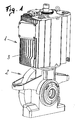
- the machine 1 is an encapsulated electrical machine 1 with mounted gearbox 2 as a motor-gear unit in cross section shown, which unit designed for traction operation is.
- unit designed for traction operation such Units, for example trams as a single-wheel drive, used.
- single wheel drives are in the portals of Bogies provided.
- the machine 1 has no active ventilation or additional cooling media.
- the dissipation of heat loss occurs by natural convection or radiation and optionally by a generated by the wind Convection, wherein the machine housing made of light metal, preferably Aluminum, is made and outside, diagonally opposite, has overlong cooling fins 3, on the later will be discussed in more detail.
- the machine housing made of light metal, preferably Aluminum, is made and outside, diagonally opposite, has overlong cooling fins 3, on the later will be discussed in more detail.
- the necessary for the cooling surface of the arranged cooling fins 3 is about a, later described, computer or data processing program calculated.
- the calculated for cooling and required surface can then be limited to the number and dimensions of Cooling fins 3 are transferred.
- the overlong cooling fins 3 can then constructively arranged so that on the one hand the calculated Surface is achieved and on the other hand, the installation conditions Account is taken.
- the machine 1 consists of a stator 4 and a, on a rotating shaft 5 fixed, rotor 6. Both the stator 4, as well as the rotor 6 are made of individual, assembled into laminated cores, Built up sheets.
- the stator 4 consists of stamped stator laminations, which laminated to the laminated stator core become. Furthermore, in the stator 4, the stator winding with the side outstanding winding heads 7 are arranged.
- the rotor 6 is also made from stamped rotor laminations which are laminated to the rotor core be and has the rotor winding with the shorting rings. 8 on.
- the shaft 5 of the machine 1 is designed such that that the stub shaft 9 of the transmission 2 is connected to the shaft 5 can be. This can be done via a positive and / or non-positive connection respectively.
- the drive-side mounting of the machine 1 takes place via the gearbox 2, which flanged to the machine housing is.
- a housing 10 made of aluminum is intended for the machine 1 shown, with which these occurring difficult Problems can be mastered and mastered as well.
- the housing 10 has outer, diagonally opposite, overlong cooling fins third on.
- the overlong cooling fins 3 create, despite encapsulation of the machine 1, through its surface the necessary cooling. This is due to the use of aluminum, because aluminum is a has a factor of 10 better thermal conductivity than cast steel. Due to this excellent thermal conductivity, the overlong Cooling fins 3 thermally effective.
- the cooling fins 3 When installed machine 1, the cooling fins 3 are arranged vertically. By this type of construction of the cooling fins 3 is a very large surface created for the heat dissipation by convection. By the course of the cooling fins 3 parallel to each other, the are arranged at least on one side of the machine 1, is Achieved a maximum cooling surface with minimal space requirements. Further, in the arrangement of the cooling fins 3 on both sides the machine 1 - through the aligned, diagonally opposite Arrangement of the cooling fins 3, the given installation conditions optimally utilized in a drive portal.
- the installation conditions in the drive portal usually predetermined.
- the machine can the installation and / or space conditions can be adjusted accordingly and can also meet these requirements Be taken into account.
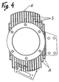
- Fig. 4 - which is a view from the side of the transmission Figure 2 shows a further increase in convection indicated surface available.
- the jacket 11 can only cover part of the surface extend the machine 1. In extreme cases, this jacket 11 also be a cylinder that covers the machine 11 quasi. It can but also the cooling fins 3 in the region of their free ends with webs 14 are connected.
- Such a jacket 11 or the connection the cooling fin tips with webs 14 brings on the one hand a drastic Reduction of noise emission and on the other hand becomes the active Cooling surface further increased.
- Such a coat 11 may be at the tips of the cooling fins 3 by means of a welded joint be provided. In the arrangement of webs 14 can these are connected to the cooling ribs 3 in the area of the cooling rib tips become.
- baffles od Like. Be provided. Through an intelligent arrangement of baffles o. The like. Can reach a suction flow over the machine 1 be, whereby the heat dissipation can be increased. How later To be more detailed, is the design of a traction machine depending on the driving game. By the driving movement becomes an air flow in the vehicle causes, for the suction flow can be exploited.
- the calculation includes the surface for cooling with is a Data processing program provided for determining state variables, in particular the temperatures and heat flows, preferably for the stationary end state and / or for the dynamic Driving, serving in the electric machine.
- This data processing program introduces the calculations Heat source network through.
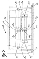
- FIG. 5 a structure of a heat source network for an electrical machine 1 shown as a schematic diagram.
- Using a data processing program will be according to the geometric Definition of the machine, such as preferably dimensions, groove shape, Winding type, material properties the structure of Heat source network 12 created. Furthermore, nodes 13 for set the heat source network 12 and between the nodes 13 defines the thermal contact resistance. From these parameters the temperatures for the stationary final state are calculated.
- At least one node each for the teeth in the stator 13a and 13b in the rotor, for the grooves in the stator 13c and in the Rotor 13d, for the air gap 13e, for the stator yoke 13f, for the Rotor yoke 13g, for each side of the winding head 13h, 13i and for the Short circuit ring set on each side 13j, 13k.
- the more precise Design of the machine can be in Statorjoch 13f and the adjacent Constructing at least one further node 131, Preferably, for the housing 10 and the cooling fins 3, set become.
- the rotor yoke 13g in the field of Wave 5 at least one further node 13m are set and the contact resistance occurring between the nodes 13b, 13m will be included in the calculation.
- the shaft 5 of the machine 1 certainly a neuralgischer machine part is also for the transmission side shaft end and the corresponding shaft end on which a brake disc arranged may be nodes 13r, 13s set. Of course you can still further nodes 13 for a higher accuracy of the calculation be determined.
- the thermal contact resistances are taken into account the dynamic behavior of the machine in operation, in particular the speed and / or speed of the vehicle during of the driving game, calculated. It follows, - also mentioned - that the machine does not respond to the temperatures of the stationary final state is calculated, but on the actual values in the Business.
- the network of thermal contact resistance is through the thermal capacities of the regions corresponding to the nodes the machine complements.
- the dynamic behavior of the machine in operation is dynamically simulated in the calculation and from this average values are calculated.
- the heat transfer coefficient ⁇ is strong on the flow conditions and the surface geometry, as well as the overlong Cooling fins, depending.
- thermal real Resistors also added thermal capacity over which the temporal dependence of the temperature distribution in the Machine can be considered.
- the Thermal capacities are due to the geometry materials and boundary conditions of the electrical machine.
- Losses include iron losses, copper losses in the stator and rotor as well as mechanical losses and so-called Additional losses, which all other unassignable Losses include.
- the parameters according to the time accordingly the driving game are used for the thermal calculation of Machine used.
- differential equations set up and by solving the temperatures or heat flows in the nodes of the heat source network, which correspond to specific locations on the machine, depending on the time is calculated.
- By juxtaposing several Driving games approach the determined temperature a certain Limit, in the so-called state of inertia.
Landscapes
- Engineering & Computer Science (AREA)
- Power Engineering (AREA)
- Physics & Mathematics (AREA)
- Thermal Sciences (AREA)
- Motor Or Generator Frames (AREA)
- Motor Or Generator Cooling System (AREA)
Applications Claiming Priority (2)
| Application Number | Priority Date | Filing Date | Title |
|---|---|---|---|
| AT15762003A AT504056B1 (de) | 2003-10-06 | 2003-10-06 | Gekapselte, elektrische maschine |
| AT15762003 | 2003-10-06 |
Publications (2)
| Publication Number | Publication Date |
|---|---|
| EP1523085A2 true EP1523085A2 (fr) | 2005-04-13 |
| EP1523085A3 EP1523085A3 (fr) | 2005-10-05 |
Family
ID=34280368
Family Applications (1)
| Application Number | Title | Priority Date | Filing Date |
|---|---|---|---|
| EP04450187A Withdrawn EP1523085A3 (fr) | 2003-10-06 | 2004-10-06 | Machine électrique fermée et méthode de dimensionnement d'une telle machine |
Country Status (3)
| Country | Link |
|---|---|
| EP (1) | EP1523085A3 (fr) |
| AT (1) | AT504056B1 (fr) |
| DE (1) | DE202004021506U1 (fr) |
Cited By (4)
| Publication number | Priority date | Publication date | Assignee | Title |
|---|---|---|---|---|
| DE202008006366U1 (de) | 2007-05-14 | 2008-07-17 | Traktionssysteme Austria Gmbh | Gehäuse für elektrische Maschinen und Dämpfungselement dafür |
| CN104885339A (zh) * | 2012-12-21 | 2015-09-02 | 万高电机设备公司 | 旋转电机壳体的热交换系统 |
| WO2017194522A1 (fr) * | 2016-05-10 | 2017-11-16 | Abb Schweiz Ag | Cadre de stator de machine électrique et machine électrique |
| CN115514138A (zh) * | 2017-01-25 | 2022-12-23 | 株式会社日立产机系统 | 电动机和使用其的压缩机 |
Families Citing this family (1)
| Publication number | Priority date | Publication date | Assignee | Title |
|---|---|---|---|---|
| DE102010025352B4 (de) | 2010-06-28 | 2019-12-24 | Audi Ag | Verfahren zum Herstellen einer elektrischen Maschine eines Kraftwagens |
Family Cites Families (12)
| Publication number | Priority date | Publication date | Assignee | Title |
|---|---|---|---|---|
| GB766951A (en) * | 1954-02-06 | 1957-01-30 | Siemens Ag | Improvements in or relating to electric mining machines |
| GB1248957A (en) * | 1968-12-16 | 1971-10-06 | Gen Electric Co Ltd | Improvements in or relating to electric motors |
| DE3501185A1 (de) * | 1985-01-16 | 1986-07-17 | Robert Bosch Gmbh, 7000 Stuttgart | Stromerzeugeraggregat |
| DE3665652D1 (en) * | 1985-02-04 | 1989-10-19 | Siemens Ag | Stator easing for a surface cooled electrical machine |
| CA2087763C (fr) * | 1992-02-11 | 2002-07-02 | Jimmy Cochimin | Carcasse de stator pour machine dynamo-electrique, et methode de fabrication de la carcasse |
| JPH06311691A (ja) * | 1993-04-15 | 1994-11-04 | Meidensha Corp | 電気自動車用モータ |
| WO1995034117A1 (fr) * | 1994-06-08 | 1995-12-14 | Precise Power Corporation | Motoalternateur a plusieurs fonctions |
| US5789833A (en) * | 1995-11-24 | 1998-08-04 | Kabushiki Kaisha Toshiba | Totally-enclosed traction motor for electric railcar |
| DE19711117C1 (de) * | 1997-03-05 | 1998-09-03 | Mannesmann Ag | Anlage zum Verdichten eines gasförmigen Mediums oder zur Erzeugung eines Vakuum |
| DE19716758C2 (de) | 1997-04-12 | 2002-01-10 | System Antriebstechnik Dresden | Gehäuselose elektrische Maschine mit mehreren unmittelbar fluiddurchströmten axialen Kühlkanälen |
| DE19808602C1 (de) * | 1998-02-28 | 1999-09-02 | Grundfos As | Vorrichtung zum äußeren Kühlen des elektrischen Antriebsmotors eines Kreiselpumpenaggregates |
| EP1087273A1 (fr) * | 1999-09-21 | 2001-03-28 | Va Tech Elin GmbH | Procédé et poste de travail pour la simulation d'une installation industrielle |
-
2003
- 2003-10-06 AT AT15762003A patent/AT504056B1/de not_active IP Right Cessation
-
2004
- 2004-10-06 EP EP04450187A patent/EP1523085A3/fr not_active Withdrawn
- 2004-10-06 DE DE200420021506 patent/DE202004021506U1/de not_active Expired - Lifetime
Cited By (7)
| Publication number | Priority date | Publication date | Assignee | Title |
|---|---|---|---|---|
| DE202008006366U1 (de) | 2007-05-14 | 2008-07-17 | Traktionssysteme Austria Gmbh | Gehäuse für elektrische Maschinen und Dämpfungselement dafür |
| CN104885339A (zh) * | 2012-12-21 | 2015-09-02 | 万高电机设备公司 | 旋转电机壳体的热交换系统 |
| CN104885339B (zh) * | 2012-12-21 | 2018-05-04 | 万高电机设备公司 | 旋转电机壳体的热交换系统 |
| WO2017194522A1 (fr) * | 2016-05-10 | 2017-11-16 | Abb Schweiz Ag | Cadre de stator de machine électrique et machine électrique |
| KR20190002619A (ko) * | 2016-05-10 | 2019-01-08 | 에이비비 슈바이쯔 아게 | 전기기계의 고정자 프레임 및 전기기계 |
| US10530214B2 (en) | 2016-05-10 | 2020-01-07 | Abb Schweiz Ag | Stator frame of an electrical machine and an electrical machine |
| CN115514138A (zh) * | 2017-01-25 | 2022-12-23 | 株式会社日立产机系统 | 电动机和使用其的压缩机 |
Also Published As
| Publication number | Publication date |
|---|---|
| DE202004021506U1 (de) | 2008-07-17 |
| EP1523085A3 (fr) | 2005-10-05 |
| AT504056A1 (de) | 2008-02-15 |
| AT504056B1 (de) | 2009-08-15 |
Similar Documents
| Publication | Publication Date | Title |
|---|---|---|
| DE19648455C2 (de) | Gekapselter Fahrmotor für elektrisches Schienenfahrzeug | |
| EP2688183B1 (fr) | Bobine électrique fabriquée selon une technique de coulage | |
| DE102019112389A1 (de) | Kühlung von Elektromotoren | |
| EP4320709A1 (fr) | Stator de machine électrique à flux axial et machine à flux axial | |
| WO2019141518A1 (fr) | Bogie d'un véhicule ferroviaire | |
| DE102010055821A1 (de) | Elektrische Maschine mit Spaltrohr und Verfahren zur Herstellung derselben | |
| DE102019106801A1 (de) | Elektrische Maschine mit Kühlung | |
| WO2019110271A1 (fr) | Machine électrique, en particulier pour un véhicule | |
| EP1515417A2 (fr) | Machine électrique fermée et méthode de coneption d'une telle machine | |
| WO2019110275A1 (fr) | Machine électrique, en particulier pour véhicule | |
| DE19743906A1 (de) | Radantriebsvorrichtung | |
| DE4111627C2 (de) | Elektromotor für ein Elektromobil zum Einbau in eine Radfelge | |
| DE102021108953B3 (de) | Stator einer elektrischen Axialflussmaschine und Axialflussmaschine | |
| DE4234145C1 (de) | Mehrphasige elektrische Maschinem mit vorgefertigten Leitersträngen und Verfahren zu ihrer Herstellung | |
| EP1523085A2 (fr) | Machine électrique fermée et méthode de dimensionnement d'une telle machine | |
| DE102023113041A1 (de) | Kühlsystem für motor mit hoher dichte | |
| DE102011012453A1 (de) | Elektrische Maschine | |
| DE102022114472A1 (de) | Axialflussmaschine, elektrischer Achsantriebsstrang und Kraftfahrzeug | |
| EP3813237B1 (fr) | Module de bobine pour une machine électrique | |
| WO2022033943A1 (fr) | Machine de traction électrique non close | |
| DE102022107665A1 (de) | Statoreinheit, Antriebseinheit und Antriebsanordnung | |
| EP2721620B1 (fr) | Ensemble d'enroulement comprenant un enroulement de bobine et un système de canaux de refroidissement | |
| DE102021108949A1 (de) | Elektrische Maschine | |
| EP3857684B1 (fr) | Machine de traction électrique sans boîtier | |
| EP0882322A1 (fr) | Procede pour refroidir un moteur a courant alternatif, notamment moteur a flux transversal et moteur a courant alternatif, notamment moteur a flux transversal |
Legal Events
| Date | Code | Title | Description |
|---|---|---|---|
| PUAI | Public reference made under article 153(3) epc to a published international application that has entered the european phase |
Free format text: ORIGINAL CODE: 0009012 |
|
| AK | Designated contracting states |
Kind code of ref document: A2 Designated state(s): AT BE BG CH CY CZ DE DK EE ES FI FR GB GR HU IE IT LI LU MC NL PL PT RO SE SI SK TR |
|
| AX | Request for extension of the european patent |
Extension state: AL HR LT LV MK |
|
| PUAL | Search report despatched |
Free format text: ORIGINAL CODE: 0009013 |
|
| AK | Designated contracting states |
Kind code of ref document: A3 Designated state(s): AT BE BG CH CY CZ DE DK EE ES FI FR GB GR HU IE IT LI LU MC NL PL PT RO SE SI SK TR |
|
| AX | Request for extension of the european patent |
Extension state: AL HR LT LV MK |
|
| 17P | Request for examination filed |
Effective date: 20060323 |
|
| AKX | Designation fees paid |
Designated state(s): AT BE BG CH CY CZ DE DK EE ES FI FR GB GR HU IE IT LI LU MC NL PL PT RO SE SI SK TR |
|
| AXX | Extension fees paid |
Extension state: MK Payment date: 20060323 Extension state: LV Payment date: 20060323 Extension state: LT Payment date: 20060323 Extension state: HR Payment date: 20060323 |
|
| 17Q | First examination report despatched |
Effective date: 20080124 |
|
| STAA | Information on the status of an ep patent application or granted ep patent |
Free format text: STATUS: THE APPLICATION HAS BEEN WITHDRAWN |
|
| 18W | Application withdrawn |
Effective date: 20080516 |