EP1523090A2 - Procédé pour la commutation d'un moteur à courant continu sans balais - Google Patents
Procédé pour la commutation d'un moteur à courant continu sans balais Download PDFInfo
- Publication number
- EP1523090A2 EP1523090A2 EP04023471A EP04023471A EP1523090A2 EP 1523090 A2 EP1523090 A2 EP 1523090A2 EP 04023471 A EP04023471 A EP 04023471A EP 04023471 A EP04023471 A EP 04023471A EP 1523090 A2 EP1523090 A2 EP 1523090A2
- Authority
- EP
- European Patent Office
- Prior art keywords
- commutation
- winding
- motor
- current
- commutation signal
- Prior art date
- Legal status (The legal status is an assumption and is not a legal conclusion. Google has not performed a legal analysis and makes no representation as to the accuracy of the status listed.)
- Withdrawn
Links
Images

Classifications
-
- H—ELECTRICITY
- H02—GENERATION; CONVERSION OR DISTRIBUTION OF ELECTRIC POWER
- H02P—CONTROL OR REGULATION OF ELECTRIC MOTORS, ELECTRIC GENERATORS OR DYNAMO-ELECTRIC CONVERTERS; CONTROLLING TRANSFORMERS, REACTORS OR CHOKE COILS
- H02P25/00—Arrangements or methods for the control of AC motors characterised by the kind of AC motor or by structural details
- H02P25/02—Arrangements or methods for the control of AC motors characterised by the kind of AC motor or by structural details characterised by the kind of motor
- H02P25/022—Synchronous motors
- H02P25/03—Synchronous motors with brushless excitation
-
- H—ELECTRICITY
- H02—GENERATION; CONVERSION OR DISTRIBUTION OF ELECTRIC POWER
- H02P—CONTROL OR REGULATION OF ELECTRIC MOTORS, ELECTRIC GENERATORS OR DYNAMO-ELECTRIC CONVERTERS; CONTROLLING TRANSFORMERS, REACTORS OR CHOKE COILS
- H02P6/00—Arrangements for controlling synchronous motors or other dynamo-electric motors using electronic commutation dependent on the rotor position; Electronic commutators therefor
- H02P6/14—Electronic commutators
- H02P6/15—Controlling commutation time
Definitions
- the invention relates to methods for commutating a brushless DC motor according to the preamble of the independent claims
- the motor current is in certain Rotor positions by electronic switching elements, e.g. Transistors, commutated. For a single-stranded motor, this happens twice per electrical revolution, wherein the voltage applied to the single winding alternately reversed becomes. In a three-stranded motor, the commutation takes place every 120 ° (Electric). For this commutation process to take place at the right time, the current rotor position must be known.
- electronic switching elements e.g. Transistors
- the usual method for detecting the rotor position in these engines is based on Hall sensors. These components are usually in the / the neutral Zone (s) of the anchor circumference arranged and capture the from permanent magnetic rotor generated magnetic field. As neutral zones are those locations of the anchor circumference designated where the Normal components of the induction are zero, ie in each case the Nutmitte of the stator. If the rotor reaches a neutral zone, each of the mechanical Commutation corresponds, generates the Hall sensor on Commutation.
- the achieved Motor current does not peak immediately after turning it on, but rather hurries applied motor voltage, that is, it will be for a certain time delayed.
- a so-called Pre-commutation practiced That is, the commutation process is started before the rotor reaches the actual commutation position Has.
- Another method of pre-commutation uses the fact that under load running motors, especially in fan applications, often a high Have moment of inertia. As a result, the operating speed changes at a Change in operating conditions only relatively slow.
- This inertia is added exploited the commutation by the time between two polarity changes the Hall signal, ie the time between two consecutive Commutation signals, is measured. If one assumes that the measured time remains constant between the next two polarity changes, the time of the pre-commutation can be calculated from the measured time and be measured with a timer.
- This timer can either hardware, e.g. with a counter-timer unit of a microcontroller, or be realized by software.
- the advantage of this method is that of Hall sensor can be placed in the neutral zone, where out Symmetrieschreibn the influence of the sensor by the winding current is minimal. The disadvantage is the slightly higher demand on the Control electronics.
- sensorless motors that do not have separate position sensors have, that is, the position of the rotor is here without Hall sensors or Generally determined without special position sensors.
- the motor windings are used as sensors.
- the rotor position is off electrically measurable quantities (motor voltage and / or motor current) derived.
- This method is especially useful for motors with external commutation electronics advantageous, since not only the sensors and possibly their holders in the engine, but also the sensor lines to the external electronics and the corresponding plug connections can be omitted.
- the pre-commutation angle can only be for a certain operating point be optimized because the angle itself by the mechanical angular position of Hall sensors is set. However, if the pre-commutation is software-based realized, the commutation angle to the desired operating point be adjusted.
- the optimization the commutation angle should cost and with little additional be technically feasible.
- the optimal commutation angle is speed and load dependent.
- the Invention shows a simple solution, as the commutation of the Motor control the working point dependent optimal commutation angle can determine. It was recognized that the optimal current flow in the Motor winding is achieved when the time of the zero crossing of the Winding current at the time of the occurrence of the commutation signal or, if calculated from the winding currents Total excitation of the current phase at the time of the commutation signal is essentially zero.
- the term "essentially zero" becomes one indicates a sufficiently small value of the winding or exciting currents, not the deviates from zero by more than a predefined amount.
- the polarity of the Winding current is evaluated.
- the time of the zero crossing of the Winding current is compared with the timing of the commutation signal. If the time of the zero crossing of the winding current is before the time of the commutation signal, then the commutation angle is too large.
- the Motor control should therefore reduce it. Is the time of the Zero crossing after the time of the commutation signal, then the Commutation angle too small.
- the engine control should therefore increase it.
- the control can automatically optimize Find commutation angle at which the zero crossing of the winding current and the commutation signal coincide in time.
- a commutation signal in particular suitable for Multi-stranded motors with unipolar current supply, it is provided that at Occurrence of a commutation signal, the amount of the winding currents detected is changed, and the commutation angle is changed so that from the Winding currents calculated total excitation of the current, i. the current one energized phase when a commutation signal occurs substantially Is zero.
- the advantage of the invention is that the commutation electronics in the motor control in addition to the commutation signal, in the case of a sensor-motor such as a Hall signal, additionally only needs to evaluate the polarity and / or the amount of the winding current to determine the optimal commutation angle. As a result, the costs for the additional sensors remain low.
- the control can be realized in software advantageously in a microcontroller of the commutation electronics.
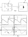
- FIG. 1 shows a simplified block diagram of a single-bristle brushless DC motor.
- the motor comprises the actual motor 10 and the associated motor controller 11 with commutation electronics, which may be integrated in the motor or may be provided externally.
- the single winding a of the stator is bipolar energized in each case for an electrical angle of 180 °, that is, in each case after 180 °, the polarity of the supply voltage V DC through the transistors T 1 to T 4 of the controller 11 is switched.
- Such single-stranded, brushless DC motors are used, for example, for driving fans.
- a position sensor e.g. arranged in the form of a Hall sensor is.
- the Hall sensor provides e.g. a rectangular output signal called Commutation signal to an input of a microcontroller of Motor controller 11 is guided. If an edge arises in the commutation signal, For example, an interrupt is triggered in the microcontroller. With this interrupt Normally, the program sequence for the commutation is started. According to The invention will additionally at this time the polarity of the bipolar Winding current detected. Is the winding current of the positive half wave at a change of the commutation signal positive ( Figure 2), the reduced Motor control the commutation angle.
- the engine control can determine the time of the next Calculate commutation and start a timer that depends on the Commutation signal determines the timing of the actual commutation.
- Figure 2 shows a representation of some motor parameters of a single-stranded 4-pole external rotor motor, in detail the commutation signal 20 (top), the motor current 21 (center) and the winding current 22 (below) at a certain speed, for example at 1980 min -1 .
- the commutation angle is 20 ° electrical, that is, the winding current 22 is at time t K 20 ° before the actual commutation, which is indicated by an edge of the commutation signal t s of the Hall sensor, switched.
- the occurring peak current in the winding is denoted by lp.
- FIG. 3 shows the same signals, commutation signal 30, motor current 31 and winding current 32 of the same motor with a changed commutation angle of 10 ° electrically.
- the motor voltage can be adjusted to the extent that the original speed of 1980 min -1 is reached again. Since the motor was loaded with a fan, the motor not only works at the same speed as in Figure 2 but also with the same torque. It can be seen that due to the changed commutation angle of now 10 ° electrical, the peak current lp in the winding has been reduced. At the same time, the recording power drops. However, by further reducing the commutation angle, the peak current increases.
- Fig. 4 shows the commutation signal 40, the motor current 41 and the winding current 42 in the same operating point at 6 ° electrical commutation.
- the peak current I P and thus also the recording power of the motor is higher than in the example according to FIG. 3, although the output power has been kept constant. That is, the engine works with worse efficiency.
- the peak current increases by approximately 20% compared to FIG. 3.
- the motor controller can find the optimal commutation angle in which the zero crossing of the winding current 32 and the change of Commutation signal 30 coincide in time substantially, as it is in Figure 3 is shown electrically at a commutation angle of 10 °.
- the invention is not limited to the embodiment of a single-stranded one shown here External rotor motor with Hall sensor for fan applications limited, but also includes all embodiments which have the same effect in the sense of the invention, in particular, multi-stranded motors, sensorless motors and indoor and Exceptional motors for various applications.
- the invention is also for the control of single or multi-stranded suitable for unipolar power supply motors.
- the invention has even the advantage that the currents e.g. to be measured with shunts which are at the same potential (- rail), what the simplified circuitry realization.
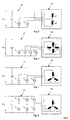
- FIG. 5 shows a simplified block diagram of a two-phase, single-phase, and unipolar DC motor 50 with motor control 51.
- the total excitation corresponds to the excitation of a single-stranded motor, if it has the same number of turns as the windings a1 and a2 (ie not the sum), and is energized with a current I E.
- I T1 and I T2 is the total current at the corresponding transistor and at the counter-parallel freewheeling diode, regardless of whether the free-wheeling diode is integrated in the transistor, as is common in MOSFETs, or whether it is designed separately.
- phase a (a 1 and a 2 ) and b (b 1 and b 2 ) electrically enclose an angle of 90 °. Therefore, the current in phase a does not affect the excitation in phase b and vice versa:
- FIG. 7 shows a simplified circuit diagram of a three-strand unipolar motor 70 with a corresponding motor control 71.
- the current can also be measured at the switch become.
- a single-strand bipolar motor for example, the switches T 1 and T 4 conduct. After commutation, the current is switched so that the switching T 3 and T 2 are turned on. When T 1 and T 4 are switched off, first the freewheeling diodes of T 2 and T 3 switch on. Only when the current has changed its polarity, the transistors T 2 and T 3 actually conduct. When the freewheeling diode conducts, the electrical potential of the winding line is approximately -0.7 V more negative than the potential of the negative intermediate circuit rail. When the transistor is conducting, the potential is slightly more positive than the negative rail potential because of the voltage drop across the transistor. Therefore, it is possible to detect the voltage drop across the switch in an advantageous and cost-saving manner instead of the winding current. The same applies to three-stranded bipolar motors according to FIG. 8.
Landscapes
- Engineering & Computer Science (AREA)
- Power Engineering (AREA)
- Control Of Motors That Do Not Use Commutators (AREA)
Applications Claiming Priority (2)
| Application Number | Priority Date | Filing Date | Title |
|---|---|---|---|
| DE10346711A DE10346711A1 (de) | 2003-10-08 | 2003-10-08 | Verfahren zur Kommutierung eines bürstenlosen Gleichstrommotors |
| DE10346711 | 2003-10-08 |
Publications (2)
| Publication Number | Publication Date |
|---|---|
| EP1523090A2 true EP1523090A2 (fr) | 2005-04-13 |
| EP1523090A3 EP1523090A3 (fr) | 2007-08-29 |
Family
ID=34306319
Family Applications (1)
| Application Number | Title | Priority Date | Filing Date |
|---|---|---|---|
| EP04023471A Withdrawn EP1523090A3 (fr) | 2003-10-08 | 2004-10-01 | Procédé pour la commutation d'un moteur à courant continu sans balais |
Country Status (4)
| Country | Link |
|---|---|
| US (1) | US7030583B2 (fr) |
| EP (1) | EP1523090A3 (fr) |
| JP (1) | JP4633433B2 (fr) |
| DE (1) | DE10346711A1 (fr) |
Cited By (1)
| Publication number | Priority date | Publication date | Assignee | Title |
|---|---|---|---|---|
| WO2015090386A1 (fr) * | 2013-12-18 | 2015-06-25 | Siemens Aktiengesellschaft | Capteur angulaire |
Families Citing this family (20)
| Publication number | Priority date | Publication date | Assignee | Title |
|---|---|---|---|---|
| SE526270C2 (sv) * | 2003-03-19 | 2005-08-09 | Forskarpatent I Syd Ab | Seriemagnetisering av synkronmotorer |
| DE10346711A1 (de) * | 2003-10-08 | 2005-05-25 | Minebea Co., Ltd. | Verfahren zur Kommutierung eines bürstenlosen Gleichstrommotors |
| DE102004001932B4 (de) * | 2004-01-14 | 2009-10-01 | Minebea Co., Ltd. | Verfahren zur Ansteuerung eines elektronisch kommutierten Motors und Motorsteuerung |
| EP1612923A1 (fr) * | 2004-07-03 | 2006-01-04 | LuK Lamellen und Kupplungsbau Beteiligungs KG | Procédé pour mesurer la vitesse d'une machine électrique |
| DE102005016333B4 (de) * | 2005-04-09 | 2024-06-13 | Minebea Mitsumi Inc. | Verfahren und Steuersystem zur Kommutierung eines einsträngigen bürstenlosen Motors |
| EP1734648B1 (fr) * | 2005-06-13 | 2012-08-15 | Brose Fahrzeugteile GmbH & Co. KG, Würzburg | Excitation asymétrique d'un moteur électrique sans capteur et sans balai |
| US7423394B2 (en) * | 2006-01-12 | 2008-09-09 | Intelasense, Llc | Single-sensor based commutation of multi-phase motor |
| US7777436B2 (en) * | 2008-07-14 | 2010-08-17 | The Bergquist Torrington Company | Sensorless drive for unipolar three phase brushless DC motors |
| DE102008036704B4 (de) | 2008-08-07 | 2015-02-12 | Ulrich Clauss | Gleichstrom-Maschine mit elektronischer Kommutierung |
| DE102008057288A1 (de) * | 2008-11-14 | 2010-05-20 | Continental Automotive Gmbh | Steuervorrichtung für einen Motor und Verfahren zum Steuern des Motors |
| DE102010026021A1 (de) * | 2009-07-11 | 2011-01-13 | Ebm-Papst St. Georgen Gmbh & Co. Kg | Einphasiger elektronisch kommutierter Motor |
| US8773055B2 (en) * | 2010-01-12 | 2014-07-08 | Ebm-Papst St. Georgen Gmbh & Co. Kg | One-phase electronically commutated motor |
| DE102012024414A1 (de) | 2012-12-14 | 2014-06-18 | Minebea Co., Ltd. | Verdampfungshemmstoff zur Verwendung in einer Schmiermittelzusammensetzung in einem fluiddynamischen Lagersystem |
| US9385639B2 (en) | 2013-05-28 | 2016-07-05 | Stmicroelectronics S.R.L. | Switching controller for electric motors and related method of controlling electric motors |
| DE102013015360A1 (de) | 2013-09-16 | 2015-03-19 | Minebea Co., Ltd. | Additivzusammensetzung zur Verwendung in einer Schmiermittelzusammensetzung in einem fluiddynamischen Lagersystem |
| DE102013015361A1 (de) | 2013-09-16 | 2015-03-19 | Minebea Co., Ltd. | Additivzusammensetzung zur Verwendung in einer Schmiermittelzusammensetzung in einem fluiddynamischen Lagersystem |
| GB201317749D0 (en) * | 2013-10-08 | 2013-11-20 | Dyson Technology Ltd | AC/DC boost converter |
| DE102017214637A1 (de) * | 2017-08-22 | 2019-02-28 | Robert Bosch Gmbh | Verfahren zum Betrieb eines elektronisch kommutierten Elektromotors |
| DE102019209851A1 (de) * | 2019-07-04 | 2021-01-07 | Robert Bosch Gmbh | Handwerkzeugmaschine mit einem elektronisch kommutierten Motor |
| KR20240030598A (ko) * | 2022-08-31 | 2024-03-07 | 주식회사 엘엑스세미콘 | 모터 드라이버, 모터 구동 시스템 및 모터 구동 방법 |
Family Cites Families (23)
| Publication number | Priority date | Publication date | Assignee | Title |
|---|---|---|---|---|
| USRE26622E (en) * | 1968-03-26 | 1969-07-01 | Synchronous motor control circuit | |
| DE2901676A1 (de) * | 1979-01-17 | 1980-08-14 | Papst Motoren Kg | Kollektorloser gleichstrommotor |
| CH658518A5 (de) * | 1982-09-04 | 1986-11-14 | Papst Motoren Gmbh & Co Kg | Sensorvorrichtung. |
| DE3517570A1 (de) * | 1985-05-15 | 1986-11-20 | Deutsche Thomson-Brandt Gmbh, 7730 Villingen-Schwenningen | Schaltung zur steuerung eines buerstenlosen elektromotors |
| US5003455A (en) * | 1990-08-14 | 1991-03-26 | Polyspede Electronics Corporation | Circuitry and method for controlling the firing of a thyristor |
| KR930004029B1 (ko) * | 1990-11-06 | 1993-05-19 | 주식회사 전연전기공업 | 트래피조이달(Trapezoidal) 구동형 무정류자 직류 전동기의 최적 정류회로 |
| JPH04185296A (ja) * | 1990-11-20 | 1992-07-02 | Seiko Epson Corp | 直流ブラシレスモータ制御装置 |
| KR100198294B1 (ko) * | 1996-06-20 | 1999-06-15 | 구자홍 | 비엘디씨 모터의 속도 제어 방법 |
| US5982122A (en) * | 1996-12-05 | 1999-11-09 | General Electric Company | Capacitively powered motor and constant speed control therefor |
| US6172498B1 (en) * | 1998-09-29 | 2001-01-09 | Rockwell Technologies, Llc | Method and apparatus for rotor angle detection |
| DE19860446A1 (de) * | 1998-12-28 | 2000-06-29 | Grundfos A S Bjerringbro | Verfahren zur Regelung eines spannungs-/frequenzumrichtergesteuerten Mehrphasen-Permanentmagnetmotors |
| DE19860448A1 (de) * | 1998-12-28 | 2000-06-29 | Grundfos A S Bjerringbro | Verfahren zur Kommutierung eines elektronisch kommutierten bürstenlosen Mehrphasen-Permanentmagnetmotors |
| DE59914199D1 (de) * | 1999-09-08 | 2007-03-29 | Melcher Rolf | Schaltungsanordnung zur Überwachung eines zum Steuern einer Last vorgesehenen elektronischen Schalters |
| DE19955248A1 (de) * | 1999-11-17 | 2001-05-31 | Bosch Gmbh Robert | Verfahren zur Verschiebung des Kommutierungszeitpunktes bei einem sensor- und bürstenlosen Gleichstrommotor sowie Anordnung zur Durchführung des Verfahrens |
| WO2001045247A1 (fr) * | 1999-12-14 | 2001-06-21 | The Penn State Research Foundation | Detection de l'angle du rotor dans un moteur synchrone a aimants permanents a vitesse nulle |
| DE10023370A1 (de) * | 2000-05-12 | 2001-11-22 | Mulfingen Elektrobau Ebm | System zur elektronischen Kommutierung eines bürstenlosen Gleichstrommotors |
| JP4288851B2 (ja) * | 2000-12-27 | 2009-07-01 | パナソニック株式会社 | モータ駆動装置 |
| JP3674578B2 (ja) * | 2001-11-29 | 2005-07-20 | 株式会社デンソー | 三相インバータの電流検出装置 |
| JP3899942B2 (ja) * | 2002-01-23 | 2007-03-28 | トヨタ自動車株式会社 | 交流発電電動機用インバータ |
| US6847186B1 (en) * | 2002-10-18 | 2005-01-25 | Raser Technologies, Inc. | Resonant motor system |
| DE10346711A1 (de) * | 2003-10-08 | 2005-05-25 | Minebea Co., Ltd. | Verfahren zur Kommutierung eines bürstenlosen Gleichstrommotors |
| DE10355651B4 (de) * | 2003-11-28 | 2011-06-01 | Minebea Co., Ltd. | Verfahren zur Optimierung des Wirkungsgrades eines unter Last betriebenen Motors |
| US20050135794A1 (en) * | 2003-12-22 | 2005-06-23 | General Electric Company | Method and system for negative torque reduction in a brushless DC motor |
-
2003
- 2003-10-08 DE DE10346711A patent/DE10346711A1/de not_active Ceased
-
2004
- 2004-09-23 US US10/948,838 patent/US7030583B2/en not_active Expired - Lifetime
- 2004-10-01 EP EP04023471A patent/EP1523090A3/fr not_active Withdrawn
- 2004-10-08 JP JP2004296623A patent/JP4633433B2/ja not_active Expired - Fee Related
Cited By (1)
| Publication number | Priority date | Publication date | Assignee | Title |
|---|---|---|---|---|
| WO2015090386A1 (fr) * | 2013-12-18 | 2015-06-25 | Siemens Aktiengesellschaft | Capteur angulaire |
Also Published As
| Publication number | Publication date |
|---|---|
| DE10346711A1 (de) | 2005-05-25 |
| US7030583B2 (en) | 2006-04-18 |
| JP2005117895A (ja) | 2005-04-28 |
| EP1523090A3 (fr) | 2007-08-29 |
| US20050077854A1 (en) | 2005-04-14 |
| JP4633433B2 (ja) | 2011-02-16 |
Similar Documents
| Publication | Publication Date | Title |
|---|---|---|
| EP1523090A2 (fr) | Procédé pour la commutation d'un moteur à courant continu sans balais | |
| DE10326606B4 (de) | Verfahren zur Kommutierung eines bürstenlosen Gleichstrommotors | |
| EP2158673B1 (fr) | Procédé d'exploitation d'un moteur à commutation électronique monophasé sur une source de tension continue et moteur pour mettre un tel procédé en oeuvre | |
| EP1499008B1 (fr) | Méthode et système de commande pour la commutation électronique d'un moteur DC sans balais | |
| DE69028910T2 (de) | Reluktanzmotor | |
| DE102010017810A1 (de) | Leistungswandler für drehende elektrische Maschinen | |
| WO2007140927A1 (fr) | Procédé de fonctionnement d'un moteur à commutation électronique et moteur pour mettre en œuvre ledit procédé | |
| DE102010061489A1 (de) | Leistungsgenerator mit verbesserter Phasensteuerbarkeit von Phasenströmen | |
| EP2965418A2 (fr) | Moteur électrique monophasé | |
| DE102004021661A1 (de) | Kommutatormotor mit mehreren Feldwicklungsgruppen | |
| DE69909449T2 (de) | Antriebssystem für bürstenlosem Motor mit Hallsensoren und selbsttätiger Bestimmung der Phasenlage der instalierten Sensoren | |
| DE102004030460B3 (de) | Elektromotorischer Antrieb für ein Fahrzeug | |
| DE102014107949A1 (de) | Verfahren und Vorrichtung zur Erkennung eines Nulldurchgangs eines Stroms durch einen Strang eines bürstenlosen Gleichstrom- motors | |
| WO2013110501A2 (fr) | Procédé pour commander un moteur bldc | |
| EP4372977A1 (fr) | Système d'entraînement | |
| DE4040926C1 (fr) | ||
| DE10332228B4 (de) | Steuerungsverfahren für einen bürstenlosen Elektromotor, insbesonde Lüftermotor | |
| DE69803885T2 (de) | Steuerungsvorrichtung für elektrische motoren | |
| DE69206503T2 (de) | Hochgeschwindigkeits-gleichstrommotor. | |
| DE102012208631A1 (de) | Verfahren und Vorrichtung zum Betrieb eines bürstenlosen Motors | |
| DE112016003094T5 (de) | Elektrowerkzeug und Verfahren zum Antreiben eines bürstenlosen Motors des Elektrowerkzeuges | |
| DE60302755T2 (de) | Verfahren und System zur Bestimmung für die elektronische Kommutierung in bürstenloser Gleichstrommaschine unabhängig von der Postionierung des Rotorlagesensors | |
| WO2006134047A1 (fr) | Commande asymetrique d'un moteur electrique exempt de capteur et de balai | |
| DE102004054862A1 (de) | Flussmodifizierer für permanenterregten Bürstenmotor unter Verwendung von gewickelten Feldspulen in Kombination mit Permanentmagneten | |
| BE1029061B1 (de) | Verfahren zum Ansteuern eines mindestens zweiphasigen bürstenlosen Motors |
Legal Events
| Date | Code | Title | Description |
|---|---|---|---|
| PUAI | Public reference made under article 153(3) epc to a published international application that has entered the european phase |
Free format text: ORIGINAL CODE: 0009012 |
|
| AK | Designated contracting states |
Kind code of ref document: A2 Designated state(s): AT BE BG CH CY CZ DE DK EE ES FI FR GB GR HU IE IT LI LU MC NL PL PT RO SE SI SK TR |
|
| AX | Request for extension of the european patent |
Extension state: AL HR LT LV MK |
|
| RIN1 | Information on inventor provided before grant (corrected) |
Inventor name: BERBATOV, NIKOLAY Inventor name: LELKES, ANDRAS DR. |
|
| PUAL | Search report despatched |
Free format text: ORIGINAL CODE: 0009013 |
|
| AK | Designated contracting states |
Kind code of ref document: A3 Designated state(s): AT BE BG CH CY CZ DE DK EE ES FI FR GB GR HU IE IT LI LU MC NL PL PT RO SE SI SK TR |
|
| AX | Request for extension of the european patent |
Extension state: AL HR LT LV MK |
|
| RIC1 | Information provided on ipc code assigned before grant |
Ipc: H02P 6/14 20060101AFI20070726BHEP |
|
| AKX | Designation fees paid | ||
| STAA | Information on the status of an ep patent application or granted ep patent |
Free format text: STATUS: THE APPLICATION IS DEEMED TO BE WITHDRAWN |
|
| 18D | Application deemed to be withdrawn |
Effective date: 20080301 |
|
| REG | Reference to a national code |
Ref country code: DE Ref legal event code: 8566 |