EP1523391B1 - Plaquette de coupe dotee d'une arete coupante principale et d'une arete coupante de finition - Google Patents
Plaquette de coupe dotee d'une arete coupante principale et d'une arete coupante de finition Download PDFInfo
- Publication number
- EP1523391B1 EP1523391B1 EP03764834A EP03764834A EP1523391B1 EP 1523391 B1 EP1523391 B1 EP 1523391B1 EP 03764834 A EP03764834 A EP 03764834A EP 03764834 A EP03764834 A EP 03764834A EP 1523391 B1 EP1523391 B1 EP 1523391B1
- Authority
- EP
- European Patent Office
- Prior art keywords
- cutting
- cutting insert
- cutting edge
- corner
- insert
- Prior art date
- Legal status (The legal status is an assumption and is not a legal conclusion. Google has not performed a legal analysis and makes no representation as to the accuracy of the status listed.)
- Expired - Lifetime
Links
Images


Classifications
-
- B—PERFORMING OPERATIONS; TRANSPORTING
- B23—MACHINE TOOLS; METAL-WORKING NOT OTHERWISE PROVIDED FOR
- B23B—TURNING; BORING
- B23B27/00—Tools for turning or boring machines; Tools of a similar kind in general; Accessories therefor
- B23B27/14—Cutting tools of which the bits or tips or cutting inserts are of special material
- B23B27/141—Specially shaped plate-like cutting inserts, i.e. length greater or equal to width, width greater than or equal to thickness
-
- B—PERFORMING OPERATIONS; TRANSPORTING
- B23—MACHINE TOOLS; METAL-WORKING NOT OTHERWISE PROVIDED FOR
- B23B—TURNING; BORING
- B23B2200/00—Details of cutting inserts
- B23B2200/08—Rake or top surfaces
- B23B2200/081—Rake or top surfaces with projections
-
- B—PERFORMING OPERATIONS; TRANSPORTING
- B23—MACHINE TOOLS; METAL-WORKING NOT OTHERWISE PROVIDED FOR
- B23B—TURNING; BORING
- B23B2200/00—Details of cutting inserts
- B23B2200/20—Top or side views of the cutting edge
- B23B2200/201—Details of the nose radius and immediately surrounding area
Definitions
- the invention relates to a cutting insert for turning under the workpiece axis fixed tool delivery direction according to the preamble of claim 1.
- the cutting insert with upper and lower deck surface and these limiting, flat side surfaces forming a corner angle ⁇ ⁇ 90 ° in the cutting corners, has at least on a top surface a straight main cutting edge and in the cutting corners within individual sections differently curved corner cutting edges with adjoining the cutting edge, circumferential, towards the center of the cutting insert sloping Spanleit matter and further characterized by reaching into the chip breaker nubs with in the top surface differently oriented stretching direction.
- Such a cutting insert is from the document EP-A-0962272 known.
- the surface quality of a workpiece with respect to roughness R a is, among other factors, system-dependent on the cutting conditions during turning, in particular the tool feed and the depth of cut. Large depth of cut and high feed allow economical machining of the workpiece at the expense of surface quality. During longitudinal turning, grooves of more or less roughness depth remain visible on the workpiece surface. Usually, therefore, when machining to the operation of coarse machining an operation of sizing at a very small depth of cut and low feed to improve the workpiece surface quality is connected. To save their own finishing work and cutting inserts are also offered that allow coarse machining with the main cutting edge and during the same operation simultaneously a finishing with a finishing cutting edge. A designed for this purpose cutting insert is in the WO 95/32071 described.
- the cutting insert according to that invention has a Corner area with five adjacent segments with different edge radii.
- the desired goal of high surface quality is achieved, in which, in addition to the main cutting edge, individual segments of the cutting edge corner region beyond the bisecting line are used at the same time during cutting.
- the edge area which is functional as a finishing cutting edge is short, compared with the possible length of use of the main cutting edge.
- Cutting inserts (with cutting corner angles ⁇ 90 °) are generally used for copying operations, ie workpiece surfaces of different angular orientations with respect to the workpiece longitudinal axis are rotated in one operation. For copy turning is often a free turning.
- the design of the cutting sets according to the above, older patent application inevitably leads to copy rotation in a profile distortion. It can, compared to standard indexable inserts, no equitable corner radii are made. Alternatively, the parameters for the infeed movement of the cutting tool to avoid otherwise occurring deviations must be laboriously corrected.
- a cutting insert for rough cutting and for simultaneous finishing particularly high demands are made in terms of chip forming and chip removal.
- the reason for this is the risk that the chip formed during the coarse machining adversely affects the sizing process and thus the quality of the workpiece surface, either by scoring on the workpiece surface as a result of coarse chips running up on it, or also as a result of damage to the sizing blade due to the main cutting edge chips.
- the cutting insert according to the aforementioned WO 95/32071 has for the chip forming and removal on a specific knob formation in the top surface area, however, at most moderate effect and this only for very short chips in the corner region of the main cutting shows.
- the object of the present invention is based on the aforementioned prior art with the disadvantages described to provide a cutting insert that results in simultaneous use of main and finishing cutting workpieces high surface finish or small roughness.
- the cutting insert should be primarily for the processing of soft and tough materials such as aluminum, non-ferrous metal and various types of plastic used.
- a cost-effective machining that is more economical than the state of the art should be possible, ie, regardless of simultaneous coarse and finish machining with a comparatively large cutting depth and large tool feed, an improved workpiece surface quality should be achieved be achieved.
- the usable length of the finishing cutting edge should be increased compared to known designs, without having to accept the previously customary deviations on the workpiece or, alternatively, having to compensate for this disadvantage by means of complex correction of the cutting tool feed.
- a cutting insert for rotating the aforementioned type which has the features according to the invention according characterizing part of claim 1.
- Advantageous embodiments are described in the subclaims.
- the cutting insert according to the invention has abruptly improved results with regard to workpiece surface quality and expandability of the cutting conditions to comparatively coarse, wide chips and large tool feed. The machining process is more economical. This will be further demonstrated below by means of the results from comparative tests.
- cutting insert according to the invention comprises embodiments with three or more corners, wherein not all corners are mandatory cutting corners.
- the latter applies, for example, rhombic cutting inserts according to the following figures.
- the cutting insert may be neutral or positive with respect to the orientation of the side surfaces, ie it has cutting edges on one or both top surfaces.
- the side surfaces are flat except for the sections in the cutting corner areas.
- the edges between the top and side surface are executed at least in the area of the main cutting edge usable as a cutting edge - see also embodiments corresponding to the figures.
- the chip breakers adjoining the cutting edges with or without chamfering are circumferentially configured on the top surface, but at least continuously in the area used as a cutting edge on both sides of the plane of symmetry to form a cutting corner.
- the Spanleitworkn can be straight or curved in profile and are depending on the material to be machined against the insert inside, or inclined against the cutting insert-bearing surface at greater or lesser constant or changing angle.
- the cutting edges of prior art cutting inserts are continuous, in side view, horizontally, i. parallel to its support surface, or from the cutting edge along the actively usable cutting edge length to the center of a cutting insert out at a constant, or alternatively at a steadily decreasing angle with respect to the support surface.
- the cutting edges of the cutting inserts according to the invention in the cutting corner i. in the region of the individual sections of the cutting edge, horizontal and fall in the adjoining the cutting corners edge regions of the usable main cutting edge at a constant angle, or under with respect to the support surface continuously changing angle towards the center of a side surface down.
- the chip breaker of a top surface opens continuously or even abruptly in a relation to the Spanleitrun raised cutting insert central area.
- the central area regularly has a hole for attachment of the cutting insert by means of a clamping screw in the tool base holder.
- nub according to the claim feature is to be understood as meaning single, rib-shaped or hump-shaped bulges in the top surface extending over the chip breaker and the central region.
- the bumps may have continuously flowing shapes or also shapes with a plurality of surfaces offset from each other by edges.
- Essential to the invention is that individual knobs have a significant longitudinal extension and in the Deck surface are oriented differently.
- the pimples cover with a part of their surface the central area of the top surface and extend into the area of the chip breaker compellingly.
- the incircle diameter of a cutting insert is a commonly used standard dimension for cutting inserts and is understood to be the diameter of that circle, in plan view of the cutting insert, which is tangent to the cutting insert or side surfaces.
- section B equal to 1.5-15% of the cutting insert incircumferential diameter, indicates to the person skilled in the art that, in contrast to known cutting inserts with segments of differently curved corner cutting edges, the sizing blade according to section B is a sizing blade of comparatively large length, which length is markedly above the known, previously realized values and has hitherto been regarded as not practical for the skilled person.
- Essential to the invention is the alignment of the chord to section B at an angle of 0 to ⁇ 5 ° to the workpiece axis, or the axis of rotation of the workpiece.
- This angle value has a fixed relation to the dimensions of the cutting insert itself insofar as the cutting insert in the tool holder is to be delivered to the workpiece under a mandatory setpoint feed direction. Only under this condition, the advantageous effect and cutting performance is achieved. In practice, irrespective of cutting inserts with simultaneous use of main and secondary cutting edge, a few setting or advancing angles have already prevailed as the standard delivery direction, e.g. the angle 93 °.
- the cutting insert according to the invention has at least on one side of the plane of symmetry a section B in the region of the cutting corner, ie as a so-called neutral version, a section B on both sides, or as a left / right version only one-sided design of section B.
- the tool can be delivered to the workpiece only with the left or right main cutting edge to the symmetry plane.
- left / right versions each have only one main cutting edge actively used for rough cutting.
- the other, adjacent to a cutting edge cutting edge, also referred to in this invention with the main cutting edge or main cutting edge, is not used for rough cutting.
- Cutting inserts with left or right cutting edge design do not provide good cutting results to the extent expected by the person skilled in the art.
- the cutting inserts according to the invention can also be carried out neutrally with only a slightly limited scope of application, ie have on both sides to the plane of symmetry of a cutting corner a finishing cutting edge in the form of a section B and adjacent each have a usable main cutting edge.
- the cutting performance in the form of the maximum applicable feed rates and cutting depth and thus the efficiency of turning compared to the left-right version are slightly lower.
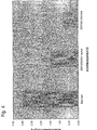
- FIG. 6 shows in a comparison workpiece roughness R a , achieved with cutting inserts according to the prior art and with cutting inserts according to the invention, once in neutral, the other time in left / right execution.
- each leg of the V-shaped knob is aligned at about 90 ° to the chord to the respective nearest section B.
- the cutting insert according to the invention is suitable for the machining of all machinable materials.
- the features of the cutting insert which are essential to the invention make it particularly advantageous for the machining of aluminum, magnesium, non-ferrous metals and non-brittle plastics.
- chip-guiding and chip-forming elements in cutting inserts is oriented in practice to the respective cutting task. Rather brittle and hard materials require cutting inserts of other design details than, for example, tough metallic materials such as aluminum and non-ferrous metal or certain classes of plastics.
- the means for chip guidance are therefore individualized to the individual case. There are no general design details.
- a further advantageous embodiment of the invention relates to a cutting insert in which the section B is subdivided into two, continuously adjacent, different in their curvature subsections B 1 and B 2 , wherein the subsection B 2 adjacent to the associated main cutting edge, and in the corner region of the section B 2, a second, elongated nub is configured, the stretching direction is performed perpendicular to the tendon at section B 2 .
- Such cutting inserts are designed according to the prior art with constant Schneckenckenradien, or Kantenverrundungen.
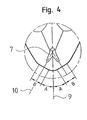
- Deviating from the known state of the art object of the present invention is a cutting insert with specific design of the cutting edge area, particularly well visible in FIG. 3 for the left / right execution and in FIG. 4 for the neutral design, which can be delivered to the workpiece both on the left and on the right.
- the symmetry plane -9- divides the cutting insert into left and right cutting insert halves.
- the cutting edge -4,5- and the subsequent inward Spanleit matter -6- are circulating in the active cutting area of the cutting insert.
- FIG. 1 is a plurality of reaching into the chip breaker -6- reaching nubs -7-, which can be seen in a plan view of a longitudinal extension and are oriented differently in their insertion direction in the top surface -1-.
- FIG. 3 shows the enlarged cutting insert cutout BB of FIG.
- the curvature of the usable as finishing cutting portion B is so low in practice that the authoritative for the angular orientation of the section B tendon can not be shown separately from the cutting edge visible. Due to its function, the long-term alignment is aligned with the workpiece axis of the workpiece to be rotated at 0 ⁇ 5 °, ie the specified tool delivery direction must be selected so that the workpiece axis and chord direction are rectified. On the other hand, the curvature of section B designed as a finishing cutting edge is such that tolerance-related angular deviations from the setpoint infeed angle do not adversely affect the sizing function or the quality of the workpiece surface.
Landscapes
- Engineering & Computer Science (AREA)
- Mechanical Engineering (AREA)
- Cutting Tools, Boring Holders, And Turrets (AREA)
- Milling Processes (AREA)
Abstract
Claims (6)
- Plaquette de coupe pour tournage dans une direction d'avance de l'outil prédéfinie de façon fixe par rapport à l'axe de la pièce à usiner, qui comprend des surfaces d'enveloppes supérieure et inférieure (1) et des parois latérales planes (2) qui les limitent et forment un angle de coin α ≤ 90 degrés dans les coins de coupe (3), ainsi qu'au moins une arête de coupe principale rectiligne (4) sur une surface d'enveloppe et une arête de coupe (5) de coin à courbures différentes à l'intérieur de segments individuels dans les angles de coupe, ainsi qu'un gradin périphérique (6) de guidage des copeaux qui se raccorde à l'arête de coupe et descend en direction du centre de la plaquette, et ainsi que des boutons allongés (7) qui pénètrent dans le gradin de guidage de copeaux et s'étendent dans des directions d'orientations différentes dans la surface d'enveloppe,
caractérisée en ce que les segments de chaque arête de coupe (5) de coin sont horizontaux en vue de côté et chaque arête de coupe principale (4) qui y est adjacente présente une zone descendant en direction du milieu (8) d'arête, en ce que l'arête de coupe (5) de coin présente sur chaque côté un segment circulaire A qui est adjacent au plan de symétrie (9) d'un coin de coupe (3) et auquel se raccorde de façon continue au moins sur un côté un segment circulaire ou elliptique B, qui n'est que faiblement incurvé par rapport au segment A et dont la longueur correspond à 1,5 à 15% du diamètre (11) du cercle inscrit de la plaquette de coupe, ledit segment B débouchant quant à lui de façon continue dans l'arête de coupe principale rectiligne (4), et la corde du segment circulaire ou elliptique B étant orientée selon un angle de 0 ± 5 degrés par rapport à la direction prédéfinie pour l'axe de la pièce à usiner, et en ce que l'orientation dans laquelle s'étend le bouton (7) le plus voisin d'un coin de coupe forme un angle β = 110 degrés à 160 degrés avec l'arête de coupe principale associée (4). - Plaquette de coupe de tournage selon la revendication 1, caractérisée en ce qu'elle comprend deux segments circulaires ou elliptiques B, un sur chaque côté du plan de symétrie, et en ce que la structure du bouton le plus voisin du coin de coupe forme approximativement un V dont les deux directions s'étendent perpendiculairement aux deux cordes respectivement les plus proches sur les segments B.
- Plaquette de coupe de tournage selon la revendication 1 ou 2, caractérisée en ce que l'arête de coupe de coin possède un segment circulaire A d'un rayon rA = 0,2 à 1,6 mm, auquel se raccorde un segment B d'un rayon r = 5 - 12 x rA ou en variante la partie incurvée plate d'une ellipse dont les rayons r1 et r2 d'ellipse sont de r1 = 5 - 12 x rA et r2 = 0,2 - 0,6 rA.
- Plaquette de coupe selon l'une des revendications 1 à 3, caractérisée en ce que l'angle β est de 130 à 140 degrés.
- Plaquette de coupe selon l'une quelconque des revendications 1 à 4, caractérisée en ce que la longueur du segment B est égale à 5 à 10% du diamètre de cercle inscrit.
- Plaquette de coupe de tournage selon la revendication 1 ou l'une des revendications 4 et 5, caractérisée en ce que le segment B est divisé, si le segment B est configuré d'un seul côté du plan de symétrie, en deux sous-segments B1 et B2, adjacents l'un à l'autre de façon continue, de courbures différentes, le sous-segment B2 étant adjacent à l'arête de coupe principale associée, et en ce que la plaquette de coupe comporte, dans la zone de coin du sous-segment B2, un deuxième bouton qui s'étend dans la direction perpendiculaire à la corde du sous-segment B2.
Applications Claiming Priority (3)
| Application Number | Priority Date | Filing Date | Title |
|---|---|---|---|
| AT4832002U | 2002-07-18 | ||
| AT0048302U AT6319U1 (de) | 2002-07-18 | 2002-07-18 | Schneideinsatz mit haupt- und schlichtschneide |
| PCT/AT2003/000188 WO2004009275A1 (fr) | 2002-07-18 | 2003-07-07 | Plaquette de coupe dotee d'une arete coupante principale et d'une arete coupante de finition |
Publications (2)
| Publication Number | Publication Date |
|---|---|
| EP1523391A1 EP1523391A1 (fr) | 2005-04-20 |
| EP1523391B1 true EP1523391B1 (fr) | 2008-04-02 |
Family
ID=3491785
Family Applications (1)
| Application Number | Title | Priority Date | Filing Date |
|---|---|---|---|
| EP03764834A Expired - Lifetime EP1523391B1 (fr) | 2002-07-18 | 2003-07-07 | Plaquette de coupe dotee d'une arete coupante principale et d'une arete coupante de finition |
Country Status (6)
| Country | Link |
|---|---|
| EP (1) | EP1523391B1 (fr) |
| AT (2) | AT6319U1 (fr) |
| AU (1) | AU2003243798A1 (fr) |
| DE (1) | DE50309541D1 (fr) |
| ES (1) | ES2301831T3 (fr) |
| WO (1) | WO2004009275A1 (fr) |
Families Citing this family (3)
| Publication number | Priority date | Publication date | Assignee | Title |
|---|---|---|---|---|
| WO2016190351A1 (fr) * | 2015-05-26 | 2016-12-01 | 京セラ株式会社 | Insert de coupe, outil de coupe et procédé de fabrication de pièces découpées utilisant ceux-ci |
| US10919095B2 (en) * | 2016-07-11 | 2021-02-16 | Kyocera Corporation | Cutting insert, cutting tool, and method of manufacturing machined product |
| US11498234B2 (en) * | 2020-05-08 | 2022-11-15 | Lamb Weston, Inc. | Tension knife for cutting food products |
Family Cites Families (4)
| Publication number | Priority date | Publication date | Assignee | Title |
|---|---|---|---|---|
| US5147159A (en) * | 1990-12-24 | 1992-09-15 | Gte Valenite Corporation | Chip control insert |
| DE4239236C2 (de) * | 1992-11-21 | 1997-06-26 | Widia Gmbh | Schneideinsatz |
| DE4437093A1 (de) * | 1994-10-17 | 1996-04-18 | Widia Gmbh | Vieleckiger Schneideinsatz |
| SE516735C2 (sv) * | 1998-06-05 | 2002-02-26 | Sandvik Ab | Vändskär för kopiersvarvning |
-
2002
- 2002-07-18 AT AT0048302U patent/AT6319U1/de not_active IP Right Cessation
-
2003
- 2003-07-07 AT AT03764834T patent/ATE390976T1/de active
- 2003-07-07 ES ES03764834T patent/ES2301831T3/es not_active Expired - Lifetime
- 2003-07-07 EP EP03764834A patent/EP1523391B1/fr not_active Expired - Lifetime
- 2003-07-07 AU AU2003243798A patent/AU2003243798A1/en not_active Abandoned
- 2003-07-07 WO PCT/AT2003/000188 patent/WO2004009275A1/fr not_active Ceased
- 2003-07-07 DE DE50309541T patent/DE50309541D1/de not_active Expired - Lifetime
Also Published As
| Publication number | Publication date |
|---|---|
| ATE390976T1 (de) | 2008-04-15 |
| EP1523391A1 (fr) | 2005-04-20 |
| DE50309541D1 (de) | 2008-05-15 |
| WO2004009275A1 (fr) | 2004-01-29 |
| ES2301831T3 (es) | 2008-07-01 |
| AU2003243798A1 (en) | 2004-02-09 |
| AT6319U1 (de) | 2003-08-25 |
Similar Documents
| Publication | Publication Date | Title |
|---|---|---|
| EP0750960B1 (fr) | Foret, en particulier pour matériaux métalliques | |
| DE69900567T2 (de) | Stechschneideinsatz | |
| DE102012017024B4 (de) | Tangential-Wendeschneidplatte | |
| DE3624861C2 (fr) | ||
| DE60318245T2 (de) | Schneideinsatz und Schneidwerkzeug | |
| EP2049295B1 (fr) | Outil de frappe pour l'usinage par enlèvement de copeaux de pièces | |
| DE69507245T2 (de) | Ein ersetzbarer Schneideinsatz | |
| DE4315251B4 (de) | Schneideinsatz | |
| DE69602258T2 (de) | Einsatz für kugelfräser | |
| DE3832547C2 (fr) | ||
| DE3882341T2 (de) | Indexierbarer Schneideinsatz. | |
| EP1087853B1 (fr) | Plaquette de coupe, outil de coupe et procede d'usinage par enlevement de matiere, notamment de surfaces de pieces a symetrie de revolution | |
| EP1455980B1 (fr) | Outil de fraisage | |
| EP0781182A1 (fr) | Plaquette de coupe | |
| DE1552360A1 (de) | Schneideeinsatz | |
| EP3694665B1 (fr) | Plaquette de coupe et outil pour l'usinage d'une pièce par enlèvement de copeaux | |
| DE60019438T2 (de) | Schneideinsatz zum einstecken | |
| EP3741483A1 (fr) | Plaquette de coupe, porte-plaquette et dispositif de coupe | |
| EP3419779A1 (fr) | Plaque d'épluchage | |
| EP2790861B1 (fr) | Plaquette de coupe amovible et outil d'usinage par enlèvement de copeaux | |
| DE69411715T2 (de) | Universeller schneidmesserrohling und aus diesem rohling hergestelltes schneidmesser | |
| DE19517311A1 (de) | Schneidplattenanordnung für Bohrwerkzeug | |
| DE102016104158A1 (de) | Schaftfräser mit konvexer Schrägeintauchkante | |
| EP1213080A1 (fr) | Outil de forage | |
| EP1047519B1 (fr) | Plaquette de coupe pour outils de fraisage |
Legal Events
| Date | Code | Title | Description |
|---|---|---|---|
| PUAI | Public reference made under article 153(3) epc to a published international application that has entered the european phase |
Free format text: ORIGINAL CODE: 0009012 |
|
| 17P | Request for examination filed |
Effective date: 20050117 |
|
| AK | Designated contracting states |
Kind code of ref document: A1 Designated state(s): AT BE BG CH CY CZ DE DK EE ES FI FR GB GR HU IE IT LI LU MC NL PT RO SE SI SK TR |
|
| AX | Request for extension of the european patent |
Extension state: AL LT LV MK |
|
| DAX | Request for extension of the european patent (deleted) | ||
| RBV | Designated contracting states (corrected) |
Designated state(s): AT DE ES FR GB IT |
|
| RAP1 | Party data changed (applicant data changed or rights of an application transferred) |
Owner name: CERATIZIT AUSTRIA GESELLSCHAFT M.B.H. |
|
| GRAP | Despatch of communication of intention to grant a patent |
Free format text: ORIGINAL CODE: EPIDOSNIGR1 |
|
| GRAS | Grant fee paid |
Free format text: ORIGINAL CODE: EPIDOSNIGR3 |
|
| GRAA | (expected) grant |
Free format text: ORIGINAL CODE: 0009210 |
|
| REG | Reference to a national code |
Ref country code: DE Ref legal event code: R081 Ref document number: 50309541 Country of ref document: DE Owner name: CERATIZIT AUSTRIA GES.M.B.H., REUTTE, AT Free format text: FORMER OWNER: CERATIZIT AUSTRIA AG, REUTTE, TIROL, AT |
|
| AK | Designated contracting states |
Kind code of ref document: B1 Designated state(s): AT DE ES FR GB IT |
|
| REG | Reference to a national code |
Ref country code: GB Ref legal event code: FG4D Free format text: NOT ENGLISH |
|
| GBT | Gb: translation of ep patent filed (gb section 77(6)(a)/1977) |
Effective date: 20080402 |
|
| REF | Corresponds to: |
Ref document number: 50309541 Country of ref document: DE Date of ref document: 20080515 Kind code of ref document: P |
|
| REG | Reference to a national code |
Ref country code: DE Ref legal event code: R096 Ref document number: 50309541 Country of ref document: DE Effective date: 20080515 |
|
| REG | Reference to a national code |
Ref country code: ES Ref legal event code: FG2A Ref document number: 2301831 Country of ref document: ES Kind code of ref document: T3 |
|
| ET | Fr: translation filed | ||
| PLBE | No opposition filed within time limit |
Free format text: ORIGINAL CODE: 0009261 |
|
| STAA | Information on the status of an ep patent application or granted ep patent |
Free format text: STATUS: NO OPPOSITION FILED WITHIN TIME LIMIT |
|
| 26N | No opposition filed |
Effective date: 20090106 |
|
| REG | Reference to a national code |
Ref country code: DE Ref legal event code: R097 Ref document number: 50309541 Country of ref document: DE Effective date: 20090102 |
|
| REG | Reference to a national code |
Ref country code: FR Ref legal event code: PLFP Year of fee payment: 14 |
|
| REG | Reference to a national code |
Ref country code: FR Ref legal event code: PLFP Year of fee payment: 15 |
|
| REG | Reference to a national code |
Ref country code: FR Ref legal event code: PLFP Year of fee payment: 16 |
|
| PGFP | Annual fee paid to national office [announced via postgrant information from national office to epo] |
Ref country code: IT Payment date: 20220726 Year of fee payment: 20 Ref country code: GB Payment date: 20220720 Year of fee payment: 20 Ref country code: ES Payment date: 20220921 Year of fee payment: 20 Ref country code: DE Payment date: 20220620 Year of fee payment: 20 Ref country code: AT Payment date: 20220721 Year of fee payment: 20 |
|
| PGFP | Annual fee paid to national office [announced via postgrant information from national office to epo] |
Ref country code: FR Payment date: 20220720 Year of fee payment: 20 |
|
| REG | Reference to a national code |
Ref country code: DE Ref legal event code: R071 Ref document number: 50309541 Country of ref document: DE |
|
| REG | Reference to a national code |
Ref country code: GB Ref legal event code: PE20 Expiry date: 20230706 Ref country code: ES Ref legal event code: FD2A Effective date: 20230726 |
|
| REG | Reference to a national code |
Ref country code: AT Ref legal event code: MK07 Ref document number: 390976 Country of ref document: AT Kind code of ref document: T Effective date: 20230707 |
|
| PG25 | Lapsed in a contracting state [announced via postgrant information from national office to epo] |
Ref country code: GB Free format text: LAPSE BECAUSE OF EXPIRATION OF PROTECTION Effective date: 20230706 Ref country code: ES Free format text: LAPSE BECAUSE OF EXPIRATION OF PROTECTION Effective date: 20230708 |