EP1523395B1 - Manipulateur miniature servant a entretenir l'interieur de tubes d'une chaudiere nucleaire - Google Patents
Manipulateur miniature servant a entretenir l'interieur de tubes d'une chaudiere nucleaire Download PDFInfo
- Publication number
- EP1523395B1 EP1523395B1 EP03765633.7A EP03765633A EP1523395B1 EP 1523395 B1 EP1523395 B1 EP 1523395B1 EP 03765633 A EP03765633 A EP 03765633A EP 1523395 B1 EP1523395 B1 EP 1523395B1
- Authority
- EP
- European Patent Office
- Prior art keywords
- manipulator
- tube sheet
- tube
- grippers
- gripper
- Prior art date
- Legal status (The legal status is an assumption and is not a legal conclusion. Google has not performed a legal analysis and makes no representation as to the accuracy of the status listed.)
- Expired - Lifetime
Links
Images




Classifications
-
- F—MECHANICAL ENGINEERING; LIGHTING; HEATING; WEAPONS; BLASTING
- F22—STEAM GENERATION
- F22B—METHODS OF STEAM GENERATION; STEAM BOILERS
- F22B37/00—Component parts or details of steam boilers
- F22B37/002—Component parts or details of steam boilers specially adapted for nuclear steam generators, e.g. maintenance, repairing or inspecting equipment not otherwise provided for
- F22B37/006—Walking equipment, e.g. walking platforms suspended at the tube sheet
-
- F—MECHANICAL ENGINEERING; LIGHTING; HEATING; WEAPONS; BLASTING
- F28—HEAT EXCHANGE IN GENERAL
- F28F—DETAILS OF HEAT-EXCHANGE AND HEAT-TRANSFER APPARATUS, OF GENERAL APPLICATION
- F28F11/00—Arrangements for sealing leaky tubes and conduits
-
- G—PHYSICS
- G21—NUCLEAR PHYSICS; NUCLEAR ENGINEERING
- G21D—NUCLEAR POWER PLANT
- G21D1/00—Details of nuclear power plant
- G21D1/02—Arrangements of auxiliary equipment
-
- G—PHYSICS
- G21—NUCLEAR PHYSICS; NUCLEAR ENGINEERING
- G21D—NUCLEAR POWER PLANT
- G21D9/00—Arrangements to provide heat for purposes other than conversion into power, e.g. for heating buildings
-
- G—PHYSICS
- G21—NUCLEAR PHYSICS; NUCLEAR ENGINEERING
- G21C—NUCLEAR REACTORS
- G21C17/00—Monitoring; Testing ; Maintaining
- G21C17/017—Inspection or maintenance of pipe-lines or tubes in nuclear installations
-
- Y—GENERAL TAGGING OF NEW TECHNOLOGICAL DEVELOPMENTS; GENERAL TAGGING OF CROSS-SECTIONAL TECHNOLOGIES SPANNING OVER SEVERAL SECTIONS OF THE IPC; TECHNICAL SUBJECTS COVERED BY FORMER USPC CROSS-REFERENCE ART COLLECTIONS [XRACs] AND DIGESTS
- Y02—TECHNOLOGIES OR APPLICATIONS FOR MITIGATION OR ADAPTATION AGAINST CLIMATE CHANGE
- Y02E—REDUCTION OF GREENHOUSE GAS [GHG] EMISSIONS, RELATED TO ENERGY GENERATION, TRANSMISSION OR DISTRIBUTION
- Y02E30/00—Energy generation of nuclear origin
-
- Y—GENERAL TAGGING OF NEW TECHNOLOGICAL DEVELOPMENTS; GENERAL TAGGING OF CROSS-SECTIONAL TECHNOLOGIES SPANNING OVER SEVERAL SECTIONS OF THE IPC; TECHNICAL SUBJECTS COVERED BY FORMER USPC CROSS-REFERENCE ART COLLECTIONS [XRACs] AND DIGESTS
- Y02—TECHNOLOGIES OR APPLICATIONS FOR MITIGATION OR ADAPTATION AGAINST CLIMATE CHANGE
- Y02E—REDUCTION OF GREENHOUSE GAS [GHG] EMISSIONS, RELATED TO ENERGY GENERATION, TRANSMISSION OR DISTRIBUTION
- Y02E30/00—Energy generation of nuclear origin
- Y02E30/30—Nuclear fission reactors
-
- Y—GENERAL TAGGING OF NEW TECHNOLOGICAL DEVELOPMENTS; GENERAL TAGGING OF CROSS-SECTIONAL TECHNOLOGIES SPANNING OVER SEVERAL SECTIONS OF THE IPC; TECHNICAL SUBJECTS COVERED BY FORMER USPC CROSS-REFERENCE ART COLLECTIONS [XRACs] AND DIGESTS
- Y10—TECHNICAL SUBJECTS COVERED BY FORMER USPC
- Y10S—TECHNICAL SUBJECTS COVERED BY FORMER USPC CROSS-REFERENCE ART COLLECTIONS [XRACs] AND DIGESTS
- Y10S165/00—Heat exchange
- Y10S165/001—Heat exchange with alarm, indicator, recorder, test, or inspection means
- Y10S165/003—Remote control inspection means
Definitions
- This invention generally concerns robotic systems and is specifically concerned with an improved robotic light-weight system for servicing the heat exchanger tubes of a nuclear steam generator. More particularly the present invention relates to a manipulator for servicing tubes extending through a tube sheet and a method of using such a manipulator.
- the steam generator typically is an upright cylindrical pressure vessel with hemispherical end sections.
- a traverse plate called a tube sheet located at the lower end of the cylindrical section, divides the steam generator into a.primary side, which is the lower hemispherical section below the tube sheet, and a secondary side above the tube sheet.
- a vertical wall bisects the primary side into an inlet section and an outlet section.
- the tube sheet is a thick carbon steel plate with an array of thousands of holes into which are inserted the ends of U-shaped tubes.
- each U-shaped tube is inserted into a hole within the tube sheet which communicates with the inlet section of the primary side and the other end is inserted in a hole within the tube sheet which communicates with the outlet section.
- the primary coolant is introduced under pressure into the inlet section of the primary side, circulates through the U-shaped tubes and exits through the outlet section.
- Water introduced into the secondary side of the steam generator circulates around the U-shaped tubes and is transformed into steam by heat given up by the primary coolant.
- limited movement arms generally are capable of moving an end effector only along a selected two-dimensional trajectory, and cannot maintain the end effector at a desired orientation along this trajectory.
- the mechanical action of limited movement robotic arms often resembles the operation of a compass used to draw circles, i.e., one end of the arm is pivotally mounted at a point on a flat tube sheet within the channel head of the nuclear steam generator, while the middle portion of the arm is telescopically extendable or retractable.
- Such arms are capable of sweeping their distal, tool-holding ends across any one of a number of arcs of greater or lesser radii which intersect with desired delivery points on the tube sheet.
- An example of such a limited movement robotic arm is the model SM-22 arm manufactured by Zetech located in Isaquah, Washington.
- Full movement arms differ from the relatively simple structure of the previously described arms in that they include six different segments which are articulated at six different motor driven joints, which in turn allows movement around six different axes.
- the more complex structure of such robotic arms allow them to use three of their axes of movement to hold an end effector at a desired orientation, and the other three axes to move the end effector across an infinite number of trajectories in three dimensions while maintaining the end effector at the desired orientation.
- Such abilities are highly advantageous in situations where it is essential to maintain the end effector at a constant orientation during a servicing operation, as is often the case with a weld head being moved around the location of a desired weld seam.
- ROSA Remote Operated Service Arm
- a vertically oriented "elbow" of the ROSA disadvantageously limits the number and length of the possible trajectories that the distal end of the arm may make without mechanically interfering with the bowl-like wall of the channel head, or the divider plate within the channel head, or the cables which vertically drape down from end effectors such as the eddy current probes used to inspect and determine the condition of the interior walls of the heat exchanger tubes.
- the prior art ROSA is configured so that a large portion of the arm is cantileverly supported from its vertically oriented elbow, which in turn applies a significant amount of life-reducing extraneous torque to the electric motor driving the joint, and reduces its payload carrying capability. Further, Applicants have observed that the motion of the distal end of such robotic arms is not smooth enough to conduct certain weld operations.
- Document JP 11174032 describes a known device and method for inspection of an intermediate heat exchanger.
- a simple, small, light-weight robot is desired that can function as a steam generator inspection and/or plugging manipulator.
- a manipulator has a weight of approximately 14 Kg (30lbs) or less and should have an approximately 32 Kg (10 lb) or greater payload capacity.
- Figure 1 shows the manipulator 10 of this invention mounted to a tube sheet 65 of a nuclear steam generator.
- the invention supports itself using two sets of expandable and translatable grippers 8 and 2 that anchor into the steam generator tube ends.
- the first major component, the base member 1, contains a set of grippers 2, solenoids 38 (that will be described hereafter with regard to Figures 7 and 9 ) to operate the manipulator and a rotation mechanism 64 (that will be described hereafter with regard to Figure 8 ) and serves as a framework for attachment of cabling and end effectors.
- a guide block 3 for eddy current inspection is shown attached to the base 1.
- the end effectors attach to the guide block as will be described hereafter.
- the second major component is the cylinder block 4.
- the cylinder block contains a linear drive motor and can rotate with respect to the base member 1 about axis 5. As is described in more detail later, the cylinder block can translate along axis 5.
- the third major component is the foot 6.
- the foot contains a linear slide 7, two grippers 8 and a lead screw 9. The foot can travel in the direction 11 relative to the cylinder block 4.
- the foot When base grippers 2 are installed in respective tubes extending through the tube sheet 65, the foot can be moved past one or several tubes along direction 11. The foot grippers 8 are then installed securing the manipulator. With the foot grippers 8 installed and the base grippers 2 disengaged, the base may be indexed along direction 11. For each movement of the foot or base, there is a vertical translation along axis 5 and within the gripper as later described. As can be seen, the predominant direction of motion is in one direction 11. To change the direction of motion and orientation of the apparatus, the foot can rotate about axis 5 as shown with arrow 12. Changing the orientation of the manipulator is accomplished by alternately engaging and releasing the foot and base grippers, respectively 8 and 2, and performing a rotational move. Typically, the rotation can be 90° for tubing on a square pitch or 60° for tubing on a triangular pitch. With the ability to rotate, the manipulator 10 becomes extremely flexible and simplified as only one linear drive axis is required.
- Figure 2 is a side view of the foot 6 and cylinder block 4. For clarity, only a portion of the base 1 is shown. Attached to the cylinder block 4 are two linear slide blocks 13 that permit free travel of linear rail 7 with attached foot grippers 8 along direction 11. To move the foot along direction 11, lead screw 9 is provided. The lead screw nut is driven internally in the cylinder block 4 as will be shown hereafter. To provide clearance between the tube sheet 65 and standoff pins 14, the foot 6, while supported by the base 1, is lowered (as shown by dimension H1) for the move. Similarly, for the base 1 to move with the foot 6 secured, the base 1 is lowered (as shown by dimension H2). For each of the grippers 2 and 8, the fingers 15 can be translated into the tube as will be described hereafter.
- Figure 3 shows a section of the cylinder block and base 1 taken along the lines B-B of Figure 1 .
- the section of the cylinder block shown in Figure 3 is enlarged in Figure 4 .
- there are two pneumatically actuated pistons 16 used to provide travel H1 or H2 as described earlier. Approximately 444N (100 lbs.) of force is obtained with the pistons 16 and the actuation is rapid due to the low viscosity of compressed air. Air is provided to cylinders 18 through ports 17 or annular area 19 depending upon the direction of desired travel. The compressed air is introduced into the cylinder block 4 through hoses 27 and fittings 20 shown in Figure 2 .
- the hoses (not shown in Figure 4 ) pass through annulus 21 along axis 5 to pneumatic solenoid valves 38 (shown in Figure 9 ) in the base 1. Routing hoses and other conduits on the axis of rotation provides protection and reduces cable management problems which otherwise arise when routed off the axis of rotation.
- the cylinder block 4 is constructed of an aluminum alloy. For wear, cylinders 18 are constructed from steel.
- two linear shafts 22 housed in four linear bearings 23 are utilized.
- the linear bearings and shafts also provide rotational rigidity between yoke 24 and cylinder block 4.
- Ball bearing 25 permits rotation of base 1 with yoke 24 and hence cylinder block 4 and foot 6.
- the rotation actuation mechanism utilizes pulley 26 and will be described hereafter.
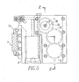
- Figure 5 is a sectional view taken along the lines D-D of Figure 2 and shows the side of the cylinder block 4.
- Linear rail 7 passes through linear slide blocks 13 when moved by lead screw 9.
- Lead screw 9 is rotationally fixed and is driven by nut 28 coupled to gear 29 which meshes with idler gear 30 and motor gear 31.
- Section EE taken through the cylinder block of Figure 5 shows the drive train in Figure 6 .
- lead screw nut 28 is supported with ball bearings 32, which provide rotation of the nut while providing sufficient axial support to restrict motion along the direction of the lead screw.
- the nut can be driven at high speed without rotational instability of the lead screw in the apparatus.
- Servomotor 66 is used to drive the gear train.
- Figure 7 is a sectional view taken along the lines C-C of Figure 1 and shows the base 1.
- Cylinder block 4 is shown in phantom in Figure 7 .
- Two base grippers 2 coupled to base plate 33 are used for anchorage to the tube sheet at the appropriate time.
- the base and foot grippers, respectively 2 and 8, have identical internal operation.
- Also shown in Figure 7 is a side view of the end effector guide block 3.
- the block can be quickly coupled to the base by sliding over four pins 34.
- Spring 35 attached to lever 36 retains the guide block when coupled.
- the end effector can be an eddy current probe, a plugging tool or other servicing tool with the orientation of the tool controlled by the guide block 3.
- the hydraulic fluid at approximately 5.5MPa (800 psi), provides the required force in a small package.
- the speed is not critical because the frequency of directional changes is low.
- the rotation mechanism is described more fully with regard to Figure 8 .
- Actuation of the cylinder block 4, base grippers 2 and foot grippers 8 is controlled with eight high flow pneumatic/electronic valves 38.
- front cover 39, solenoid housing 40 and rear cover 41 are provided for protection of the hoses and cabling.
- Figure 8 is a sectional view taken along the lines F-F of Figure 7 and shows the rotation mechanism of this invention.
- hydraulic fluid is introduced in chamber 42 forcing one piston 43 to translate and draw tension on cable 44.
- Cable 44 is coupled to pulley 26 with plunger 45.
- plunger 45 As the cable 44 translates, block 46 rotates until contact is made with stop 47. Stops 47 can be accurately located and pinned for 90° or 60° rotation.
- Figure 9 is a sectional view taken along the lines G-G of Figure 7 and shows the eight pneumatic valves 38 attached to a "U" shaped manifold 48. Compressed air is supplied to the manifold through fitting 49 and exits through the respective fitting 50 when a valve is actuated.
- the shape of the manifold provides access to annulus 21 for routing of hoses and cables.
- Two holes 51 are provided in rear cover 41 to accept the pins from a loading fixture that is used to remotely load the manipulator 10 in through the steam generator manway to the tube sheet where the grippers can be actuated to support the manipulator.
- Figure 10A shows a camlock gripper used to secure the manipulator 10 to the tube sheet 65.
- standoff pins 14 are placed in contact with the tube sheet using the cylinder block 4.
- Compressed air is released from chamber 52 ( Figure 10B ) through fitting 61 (shown in Figures 2 and 3 ) permitting springs 53 to raise actuator cylinder 54 placing gripper fingers 55 within the steam generator tube.
- Guide pin 60 maintains alignment of the cylinder 54 with the gripper.
- a limit switch 69 which is actuated by the guide pin 60, can be used to verify insertion.
- the guide pin 60 is protected within housing 72.
- the limit switch has three functions: (1) To assure that the gripper is in the full up position prior to activation of the gripper fingers 55 to press out against the corresponding heat exchanger tubes; (2) To detect if the camlock does not fully grip the corresponding heat exchanger tube (the limit switch will indicate that the gripper is not fully up when the gripper is pulled downward after the gripper fingers are radially extenuated, to fully seat the robot standoff pins 14 against the tube sheet 65); and (3) To detect if there is a missing tube, e.g., at the end of a row or column, or a plugged tube, because the gripper will not fully insert. This latter feature can be used to verify the position of the robot as it moves across the tube sheet and is a significant feature of this invention.
- actuator piston 56 With the gripper fingers 55 inserted in the tube, actuator piston 56 is forced upward with compressed air supplied through fitting 57. As the actuator piston travels upward, balls 58 roll on tapered raceways 59 bringing gripper fingers in tight contact with the tube. Balls are used to reduce friction between the gripper fingers and the actuator piston enabling a high contact force, e.g., approximately 4,450N (1,000 lbs), to be obtained with a relatively small pneumatic piston diameter. The low rolling friction of the balls eliminates the self-locking property of small angle tapers.
- the next operational sequence for the gripper is to pressurize chamber 52 which attempts to remove the gripper fingers from the tube. Since the gripper fingers are secured to the tube, the entire gripper is biased upward forcing pins 14 in close contact with the tube sheet. With the pins tightly against the tube sheet, the manipulator is forced to stay parallel and in close proximity to the tube sheet.
- the following steps are performed. Compressed air is expelled from chamber 52 relieving the force on the gripper fingers 55.
- the actuator pin is lowered by introducing compressed air into fitting 62 while releasing air through fitting 57. Nose cone 63 ensures the balls are returned to their original position and that gripper fingers 55 are captured.
- the actuator cylinder 54 is then lowered by pressurizing chamber 52.
- Figure 10C is a cross section taken along the lines H-H of Figure 10A showing a second embodiment of the gripper of this invention.
- Like reference characters refer to the corresponding elements previously described with respect to Figure 10B .
- the difference in the embodiment of Figure 10C over that of Figure 10B is that a spring 67 has been added around the top of the actuator piston 56 to bias the fingers 55 against the corresponding heat exchanger tube when the fingers are inserted within the tube to prevent an unintentional release.
- the ball bearings 58 are retained within a sleeve, but travel as previously stated along the raceway when the piston 56 is actuated to force the fingers 55 radially outward.
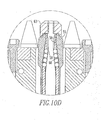
- FIG 10D is an enlargement of the gripping finger area of the grippers shown in Figure 10C where it can be appreciated that the bearings 58 are retained within a sleeve 68 each supported within its own pocket and free to roll as the actuator piston moves up to force the fingers 55 radially outward.
- air is introduced through the fitting 62 to force the piston in the opposite direction and the fingers 55 are forced inward, in turn forcing the ball bearings 58 within the sleeve 68 downward until they are seated at their lower extent of travel and the fingers 55 are captured by the nose cone 63.
- the bearing balls 58 will be forced to the lowest position when the nose cone 63 is retracted.
- this invention provides a manipulator for servicing nuclear steam generators that can accurately move at high velocity and has versatile positioning capability.
- a significant benefit of the small size is reduced time for set-up and installation in the field.
- Multiple manipulators can be utilized on each side of the channel head to reduce inspection time.
- the weight of the manipulator is preferably approximately 14Kg (30 lbs) or less and has an approximately 32Kg (70 lb) payload capability.
Landscapes
- Engineering & Computer Science (AREA)
- Physics & Mathematics (AREA)
- General Engineering & Computer Science (AREA)
- High Energy & Nuclear Physics (AREA)
- Thermal Sciences (AREA)
- Mechanical Engineering (AREA)
- Plasma & Fusion (AREA)
- Manipulator (AREA)
Claims (11)
- Manipulateur pour l'entretien des tubes s'étendant à travers une plaque tubulaire (65), comprenant :(a) un élément de base allongé (1), comportant un support pour supporter des outils ou un dispositif d'inspection, l'élément de base comportant en outre au moins un élément de préhension (2) pour saisir de manière amovible un tube s'étendant à travers la plaque tubulaire (65) ;(b) un élément de bloc (4), connecté à l'élément de base (1), en vue d'un déplacement linéaire et d'une rotation par rapport à celui-ci, le déplacement linéaire se faisant dans une direction essentiellement perpendiculaire à une dimension longitudinale de l'élément de base ; et(c) un élément de pied (6), connecté à l'élément de bloc (4), en vue d'un déplacement linéaire par rapport à celui-ci, l'élément de pied comportant au moins un élément de préhension (8) pour saisir de manière amovible un tube s'étendant à travers la plaque tubulaire (65), l'élément de bloc entraînant le déplacement de l'élément de base vers l'élément de pied et à l'écart de celui-ci ;dans lequel au moins un des éléments de préhension (2, 8) exerce une force dans une direction, pour entraîner l'élément (1, 6) qui y est associé vers la plaque tubulaire (65) et
englobant une butée (14), servant, en coopération avec ledit au moins un des éléments de préhension exerçant la force pour entraîner ledit élément dans la direction de la plaque tubulaire (65), à maintenir ledit élément à une distance fixe prédéterminée de la plaque tubulaire (65). - Manipulateur selon la revendication 1, dans lequel l'élément de bloc (4) présente deux directions de déplacement linéaire entre l'élément de bloc (4) et l'élément de base (1), les deux directions étant de préférence des directions horizontale et verticale.
- Manipulateur selon l'une quelconque des revendications précédentes, dans lequel l'élément de bloc (4) et l'élément de pied (6) comportent chacun au moins deux éléments de préhension espacés (2, 8).
- Manipulateur selon l'une quelconque des revendications précédentes, dans lequel chacun des éléments de préhension (2, 8) englobe des doigts d'insertion (55), pouvant respectivement être insérés dans un tube correspondant des tubes s'étendant à travers la plaque tubulaire (65).
- Manipulateur selon la revendication 4, englobant un interrupteur de fin de course (69) correspondant à chaque élément de préhension, vérifiant un degré d'insertion acceptable dans le tube correspondant.
- Manipulateur selon les revendications 4 ou 5, dans lequel les doigts d'insertion (55) sont poussés contre l'intérieur du tube correspondant par un piston interne (56), entraînant la remontée de paliers (58) le long d'un chemin de roulement conique (59) entre le piston (56) et l'intérieur des doigts d'insertion (55), poussant ainsi les doigts d'insertion vers l'extérieur contre l'intérieur du tube correspondant.
- Manipulateur selon la revendication 6, dans lequel les doigts d'insertion (55) sont sollicités par ressort dans une position de préhension lors de leur insertion à une distance prédéterminée dans les tubes, pour empêcher une perte de la force de préhension en cas de perte de la force motrice du piston (56).
- Manipulateur selon l'une quelconque des revendications précédentes, dans lequel le poids du manipulateur correspond à environ 14 kg (30 libres) ou moins.
- Manipulateur selon la revendication 8, dans lequel le manipulateur supporte une charge utile de 32 kg (70 livres) ou moins.
- Manipulateur selon l'une quelconque des revendications précédentes, englobant des entraînements pneumatique et/ou hydraulique en combinaison avec un seul entraînement motorisé.
- Procédé d'utilisation d'un manipulateur selon l'une quelconque des revendications précédentes, le procédé comprenant les étapes ci-dessous :dimensionnement du manipulateur de sorte à permettre la suspension de plus d'un manipulateur à actionnement indépendant, ayant essentiellement la même conception, sur un côté inférieur de la plaque tubulaire (65), dans une section d'entrée ou de sortie d'une tête de canal hémisphérique d'un générateur de vapeur ; etactionnement des manipulateurs en parallèle, de préférence en même temps.
Applications Claiming Priority (5)
| Application Number | Priority Date | Filing Date | Title |
|---|---|---|---|
| US39800002P | 2002-07-22 | 2002-07-22 | |
| US398000P | 2002-07-22 | ||
| US620013 | 2003-07-15 | ||
| US10/620,013 US7314343B2 (en) | 2002-07-22 | 2003-07-15 | Miniature manipulator for servicing the interior of nuclear steam generator tubes |
| PCT/US2003/022290 WO2004009287A1 (fr) | 2002-07-22 | 2003-07-17 | Manipulateur miniature servant a entretenir l'interieur de tubes d'une chaudiere nucleaire |
Publications (3)
| Publication Number | Publication Date |
|---|---|
| EP1523395A1 EP1523395A1 (fr) | 2005-04-20 |
| EP1523395A4 EP1523395A4 (fr) | 2005-11-23 |
| EP1523395B1 true EP1523395B1 (fr) | 2015-08-19 |
Family
ID=30773053
Family Applications (1)
| Application Number | Title | Priority Date | Filing Date |
|---|---|---|---|
| EP03765633.7A Expired - Lifetime EP1523395B1 (fr) | 2002-07-22 | 2003-07-17 | Manipulateur miniature servant a entretenir l'interieur de tubes d'une chaudiere nucleaire |
Country Status (6)
| Country | Link |
|---|---|
| US (1) | US7314343B2 (fr) |
| EP (1) | EP1523395B1 (fr) |
| KR (1) | KR101018499B1 (fr) |
| AU (1) | AU2003256581A1 (fr) |
| ES (1) | ES2549853T3 (fr) |
| WO (1) | WO2004009287A1 (fr) |
Families Citing this family (34)
| Publication number | Priority date | Publication date | Assignee | Title |
|---|---|---|---|---|
| US7314343B2 (en) * | 2002-07-22 | 2008-01-01 | Westinghouse Electric Co. Llc | Miniature manipulator for servicing the interior of nuclear steam generator tubes |
| US7533715B1 (en) * | 2003-09-26 | 2009-05-19 | Areva Np Inc. | Tube walker for examination and repair of steam generators |
| KR101074945B1 (ko) | 2004-12-30 | 2011-10-18 | 두산중공업 주식회사 | 원자력 증기발생기의 전열관 결함보수용 이송장치 |
| US8506900B1 (en) * | 2008-09-25 | 2013-08-13 | Jonathan J. Ricciardi | Methods and apparatuses for applying agent to objects |
| US8746089B2 (en) * | 2009-01-19 | 2014-06-10 | Babcock & Wilcox Nuclear Energy, Inc. | Apparatus for automated positioning of eddy current test probe |
| EP2430436A1 (fr) * | 2009-05-14 | 2012-03-21 | Westinghouse Electric Company LLC | Systeme d'inspection de tube sans câble d'attache |
| US20100329408A1 (en) * | 2009-06-24 | 2010-12-30 | Sergey Fiodorov | Systems, Apparatuses and Methods of Gripping, Cutting and Removing Objects |
| US8944192B2 (en) | 2010-04-20 | 2015-02-03 | Savannah River Nuclear Solutions, Llc | Robotic platform for traveling on vertical piping network |
| KR101109140B1 (ko) * | 2010-10-25 | 2012-02-24 | 한국수력원자력 주식회사 | 핑거 그립형 증기발생기의 전열관 검사로봇 |
| KR101295068B1 (ko) * | 2011-07-13 | 2013-08-08 | 한국수력원자력 주식회사 | 캠락형 증기발생기의 검사용 경량로봇 |
| US9058905B2 (en) * | 2012-04-06 | 2015-06-16 | Ihi Southwest Technologies | Automated inside reactor inspection system |
| US8973648B2 (en) | 2012-05-10 | 2015-03-10 | Westinghouse Electric Company Llc | Tubesheet gripping mechanism and method |
| US8938044B2 (en) * | 2012-05-10 | 2015-01-20 | Westinghouse Electric Company Llc | Tubesheet walker for heat exchanger inspections |
| KR101494455B1 (ko) * | 2013-01-31 | 2015-02-17 | 한전케이피에스 주식회사 | 원자로 헤드 관통관 검사 장치 |
| US9279582B2 (en) | 2013-05-10 | 2016-03-08 | Westinghouse Electric Company Llc | Method and apparatus for delivering a tool to the interior of a heat exchange tube |
| CN103979033A (zh) * | 2014-05-20 | 2014-08-13 | 中科华核电技术研究院有限公司 | 核电站蒸汽发生器二次侧爬壁车 |
| CN104058020B (zh) * | 2014-07-06 | 2016-01-27 | 衢州图艺工业设计有限公司 | 一种多吸盘高处工作机 |
| US10988191B2 (en) * | 2014-08-20 | 2021-04-27 | Hydraulic Systems, Llc | Load transporting apparatus and methods of using same |
| JP6489901B2 (ja) * | 2015-03-31 | 2019-03-27 | 日立造船株式会社 | 超音波検査装置 |
| KR101714451B1 (ko) * | 2015-12-18 | 2017-03-09 | 김병훈 | 원자로 스팀가스 튜브관의 내부검사장비의 홀딩장치 |
| CN105945962B (zh) * | 2016-05-19 | 2018-01-30 | 哈尔滨工业大学 | 用于蒸汽发生器热管检测的关节式爬行机器人 |
| CN106641574B (zh) * | 2016-10-25 | 2019-09-17 | 核动力运行研究所 | 一种全气动式管板爬行器结构 |
| DE102016013245B4 (de) * | 2016-11-08 | 2025-10-16 | Westinghouse Electric Germany Gmbh | Bohrgerät für das Bearbeiten von Rohren in radioaktiver Umgebung |
| CN108267162A (zh) * | 2016-12-30 | 2018-07-10 | 核动力运行研究所 | 一种蒸汽发生器传热管双探头检查定位装置 |
| CN108986941B (zh) * | 2017-06-02 | 2024-02-09 | 核动力运行研究所 | 一种传热管检修定位装置结构 |
| US11717865B2 (en) | 2017-09-06 | 2023-08-08 | Ge-Hitachi Nuclear Energy Americas Llc | Method of cleaning a nozzle of a jet pump assembly of a nuclear reactor |
| US10751767B2 (en) | 2017-09-06 | 2020-08-25 | Ge-Hitachi Nuclear Energy Americas Llc | Method of cleaning a throat section of a jet pump assembly of a nuclear reactor |
| CN109968363A (zh) * | 2017-12-27 | 2019-07-05 | 核动力运行研究所 | 一种传热管检修多足机器人 |
| CN110335689B (zh) * | 2019-07-12 | 2020-08-28 | 哈尔滨工程大学 | 内孔定位装置、定位方法及爬行机构 |
| CN111717609A (zh) * | 2020-05-13 | 2020-09-29 | 中核武汉核电运行技术股份有限公司 | 用于蒸汽发生器管板检修的运载平台及控制方法 |
| US12202126B2 (en) | 2020-06-03 | 2025-01-21 | Westinghouse Electric Company Llc | Articulated manipulator for navigating and servicing a heat exchanger |
| CN118722900A (zh) | 2023-03-30 | 2024-10-01 | 加拿大双赢机器人有限公司 | 用于沿着表面攀爬和/或移动的机器人 |
| DE102023120947A1 (de) * | 2023-08-07 | 2025-02-13 | SK2 ROBOTICS UG (haftungsbeschränkt) | Mobiler Roboter zum Einsatz auf einem Rohrspiegel sowie Verfahren zur Fortbewegung eines solchen Roboters auf einem Rohrspiegel |
| KR102648406B1 (ko) * | 2023-09-12 | 2024-03-18 | 주식회사 지스콥 | 배관 내부 검사 시스템의 프로브 접속 장치 |
Citations (5)
| Publication number | Priority date | Publication date | Assignee | Title |
|---|---|---|---|---|
| US4298054A (en) * | 1979-02-05 | 1981-11-03 | Intercontrole S.A. | Method of withdrawing a mobile sensor from a heat exchanger |
| US4653971A (en) * | 1984-06-22 | 1987-03-31 | The Societe Anonyme Barras-Provence | Device for selectively positioning a tool carried by a vehicle moving on the perforated plate of a bank of tubes |
| EP0276659A2 (fr) * | 1987-01-27 | 1988-08-03 | Westinghouse Electric Corporation | Appareil et méthode pour introduire simultanément un manchon de renforcement et un mandrin dans un tube |
| EP0477572A1 (fr) * | 1990-09-05 | 1992-04-01 | Mitsubishi Jukogyo Kabushiki Kaisha | Dispositif d'obturation pour échangeur de chaleur |
| JPH11174032A (ja) * | 1997-12-10 | 1999-07-02 | Toshiba Corp | 中間熱交換器の検査装置およびその方法 |
Family Cites Families (56)
| Publication number | Priority date | Publication date | Assignee | Title |
|---|---|---|---|---|
| AT336926B (de) * | 1972-12-22 | 1977-06-10 | Siemens Ag | Inspektions- und reparatureinrichtung fur dampferzeuger |
| US3913752A (en) * | 1973-08-01 | 1975-10-21 | Combustion Eng | Remotely movable platform |
| US3913452A (en) * | 1973-08-01 | 1975-10-21 | Combustion Eng | Remotely movable platform |
| US3889820A (en) * | 1973-08-01 | 1975-06-17 | Combustion Eng | Method and apparatus for suspendedly supporting a platform |
| JPS5157489A (en) * | 1974-11-15 | 1976-05-19 | Mitsubishi Heavy Ind Ltd | Jidokensasochino kontorooruhoho |
| FR2309314A1 (fr) * | 1974-12-05 | 1976-11-26 | Framatome Sa | Dispositif de positionnement selectif d'un organe sur une plaque tubulaire |
| US4018344A (en) * | 1975-11-18 | 1977-04-19 | Combustion Engineering, Inc. | Three-position actuator and apparatus incorporating same |
| US4018345A (en) * | 1975-11-18 | 1977-04-19 | Combustion Engineering, Inc. | Surface traversing apparatus |
| US4018346A (en) * | 1975-11-18 | 1977-04-19 | Combustion Engineering, Inc. | Mounting arrangement for anchor fingers on a surface traversing apparatus |
| US4074814A (en) * | 1976-03-26 | 1978-02-21 | Combustion Engineering, Inc. | Method and apparatus for controlling surface traversing device |
| US4216893A (en) * | 1977-03-08 | 1980-08-12 | Westinghouse Electric Corp. | Apparatus for remotely repairing tubes in a steam generator |
| US4427317A (en) * | 1978-09-18 | 1984-01-24 | Westinghouse Electric Corp. | Expandable camlock |
| US4158415A (en) * | 1978-01-09 | 1979-06-19 | Westinghouse Electric Corp. | Remote access manipulator |
| US4213732A (en) * | 1978-04-13 | 1980-07-22 | Westinghouse Electric Corp. | Apparatus for remotely repairing tubes in a steam generator |
| US4200424A (en) * | 1978-04-14 | 1980-04-29 | Westinghouse Electric Corp. | Remotely controlled tool positioning table |
| FR2437341A1 (fr) * | 1978-09-29 | 1980-04-25 | Commissariat Energie Atomique | Vehicule apte a se deplacer avec adherence sur une surface quelconque |
| US4261094A (en) * | 1978-10-18 | 1981-04-14 | Westinghouse Electric Corp. | Heat exchanger tube and tube sheet location sensing device |
| FR2457741A1 (fr) * | 1979-05-31 | 1980-12-26 | Framatome Sa | Porte-outil mobile pour travail sur une plaque tubulaire |
| FR2471026A1 (fr) * | 1979-11-30 | 1981-06-12 | Intercontrole Sa | Appareil porte-sonde pour le controle des tubes d'un generateur de vapeur |
| US4329769A (en) * | 1979-12-05 | 1982-05-18 | Westinghouse Electric Corp. | Apparatus for working on tubesheets |
| US4521844A (en) * | 1980-05-30 | 1985-06-04 | Westinghouse Electric Corp. | Manipulator control system and apparatus for decontaminating nuclear steam generators |
| US4790065A (en) * | 1980-07-01 | 1988-12-13 | Westinghouse Electric Corp. | Method for servicing a steam generator |
| DE3029811A1 (de) * | 1980-08-06 | 1982-02-18 | Kraftwerk Union AG, 4330 Mülheim | Manipulator zur fernbedienbaren inspektion und gegebenenfalls reparatur von waermtauscherrohren |
| US4406856A (en) * | 1980-09-29 | 1983-09-27 | Westinghouse Electric Corp. | Removal of portions of tubes from steam generator of nuclear reactor |
| FR2503921A1 (fr) * | 1981-04-10 | 1982-10-15 | Commissariat Energie Atomique | Dispositif pour le positionnement d'un organe en vis-a-vis des perforations d'une plaque et procede de montage a distance d'un tel dispositif |
| DE3122660C2 (de) * | 1981-06-06 | 1986-06-19 | Brown Boveri Reaktor GmbH, 6800 Mannheim | Einrichtung zur Inspektion und/oder zur Reparatur der Rohre eines Dampferzeugers einer Kernkraftanlage |
| FR2513927A1 (fr) * | 1981-10-05 | 1983-04-08 | Framatome Sa | Tele-manipulateur d'intervention dans une boite a eau de generateur de vapeur |
| US4449599A (en) * | 1982-09-27 | 1984-05-22 | Combustion Engineering, Inc. | Finger walker for tube sheet |
| US4688327A (en) * | 1983-10-03 | 1987-08-25 | Westinghouse Electric Corp. | Sleeving of tubes of steam generator |
| US4639994A (en) * | 1983-10-03 | 1987-02-03 | Westinghouse Electric Corp. | Suspension of tools for sleeving of tubes of steam generator |
| US4804038A (en) * | 1983-10-11 | 1989-02-14 | The Babcock & Wilcox Company | Remotely installed, operated and removed manipulator for steam generator |
| GB8408458D0 (en) * | 1984-04-02 | 1984-05-10 | Stewart D E S | Vehicle |
| US4643472A (en) * | 1984-12-24 | 1987-02-17 | Combustion Engineering, Inc. | Rapid installation tube gripper |
| DE3509177C1 (de) * | 1985-03-14 | 1986-10-02 | Brown Boveri Reaktor GmbH, 6800 Mannheim | Einrichtung zum Einbringen eines zylindrischen Koerpers,insbesondere einer Huelse,in ein Rohr eines Dampferzeugers |
| GB8618044D0 (en) * | 1986-07-24 | 1986-09-03 | Sheeter E | Vehicle |
| DE8712638U1 (de) * | 1987-09-18 | 1987-12-10 | Siemens AG, 1000 Berlin und 8000 München | Vorrichtung zum Einbringen eines Gerätes in einen Wärmetauscher |
| FR2625459B1 (fr) * | 1987-12-31 | 1990-06-15 | Aerospatiale | Mobile autonome du type robot pour le transport d'un outil a vitesse constante |
| US4901578A (en) * | 1988-05-20 | 1990-02-20 | Westinghouse Electric Corp. | Probe carrier drive assembly |
| US5061176A (en) * | 1988-06-30 | 1991-10-29 | Westinghouse Electric Corp. | Apparatus and process for simultaneously positioning and oscillating a plurality of probes in the heat exchanger tubes of a nuclear steam generator |
| DE8813215U1 (de) * | 1988-10-21 | 1988-12-15 | ABB Reaktor GmbH, 6800 Mannheim | Werkzeug- und Inspektionsgeräteträger für eine Einrichtung zur Prüfung oder Reparatur eines Dampferzeugers |
| FR2643135B1 (fr) * | 1989-02-15 | 1991-06-21 | Barras Provence | Vehicule d'exploration et de maintenance des tubes de generateurs de vapeur ou similaires |
| FR2644568B1 (fr) * | 1989-03-16 | 1991-07-05 | Intercontrole Sa | Dispositif d'intervention, notamment pour le controle, l'inspection et la maintenance des echangeurs de chaleur |
| US5355063A (en) * | 1990-11-01 | 1994-10-11 | Westinghouse Electric Corp. | Robotic system for servicing the heat exchanger tubes of a nuclear steam generator |
| FR2674938B1 (fr) * | 1991-04-05 | 1993-07-30 | Barras Provence | Vehicule d'exploration et de maintenance d'un reseau de tubes d'un generateur de vapeur. |
| US5178820A (en) * | 1991-09-06 | 1993-01-12 | B&W Nuclear Service Company | Tool positioning assembly |
| JPH05131382A (ja) * | 1991-11-11 | 1993-05-28 | Takeshi Yanagisawa | 歩行ロボツト |
| JP3365802B2 (ja) * | 1992-12-01 | 2003-01-14 | 健 柳沢 | 歩行ロボット |
| US5429009A (en) * | 1993-05-20 | 1995-07-04 | Carnegie Mellon University | Robot with cruciform geometry |
| FR2722324B1 (fr) * | 1994-07-07 | 1996-10-04 | Framatome Sa | Dispositif de pose et d'extraction d'un manchon de blocage d'un tube-guide dans un embout demontable d'un assemblage combustible de reacteur nucleaire |
| US5611948A (en) * | 1994-10-31 | 1997-03-18 | Westinghouse Electric Corporation | Apparatus and method for remotely positioning a probe in a tubular member |
| JP3165630B2 (ja) * | 1995-12-07 | 2001-05-14 | 三菱重工業株式会社 | 走行式測温及び目視検査装置 |
| US5890553A (en) * | 1996-08-01 | 1999-04-06 | California Institute Of Technology | Multifunction automated crawling system |
| EP1021693A4 (fr) * | 1996-10-11 | 2002-07-10 | Foster Miller Inc | Systeme de nettoyage, d'inspection et de reparation d'un generateur de vapeur a faisceaux superieurs |
| TW463028B (en) * | 1998-04-21 | 2001-11-11 | Hitachi Shipbuilding Eng Co | Working robot for heat exchangers and operating method thereof |
| US6681839B1 (en) * | 2001-02-23 | 2004-01-27 | Brent A. Balzer | Heat exchanger exchange-tube cleaning lance positioning system |
| US7314343B2 (en) * | 2002-07-22 | 2008-01-01 | Westinghouse Electric Co. Llc | Miniature manipulator for servicing the interior of nuclear steam generator tubes |
-
2003
- 2003-07-15 US US10/620,013 patent/US7314343B2/en not_active Expired - Lifetime
- 2003-07-17 EP EP03765633.7A patent/EP1523395B1/fr not_active Expired - Lifetime
- 2003-07-17 KR KR1020057001023A patent/KR101018499B1/ko not_active Expired - Lifetime
- 2003-07-17 AU AU2003256581A patent/AU2003256581A1/en not_active Abandoned
- 2003-07-17 WO PCT/US2003/022290 patent/WO2004009287A1/fr not_active Ceased
- 2003-07-17 ES ES03765633.7T patent/ES2549853T3/es not_active Expired - Lifetime
Patent Citations (5)
| Publication number | Priority date | Publication date | Assignee | Title |
|---|---|---|---|---|
| US4298054A (en) * | 1979-02-05 | 1981-11-03 | Intercontrole S.A. | Method of withdrawing a mobile sensor from a heat exchanger |
| US4653971A (en) * | 1984-06-22 | 1987-03-31 | The Societe Anonyme Barras-Provence | Device for selectively positioning a tool carried by a vehicle moving on the perforated plate of a bank of tubes |
| EP0276659A2 (fr) * | 1987-01-27 | 1988-08-03 | Westinghouse Electric Corporation | Appareil et méthode pour introduire simultanément un manchon de renforcement et un mandrin dans un tube |
| EP0477572A1 (fr) * | 1990-09-05 | 1992-04-01 | Mitsubishi Jukogyo Kabushiki Kaisha | Dispositif d'obturation pour échangeur de chaleur |
| JPH11174032A (ja) * | 1997-12-10 | 1999-07-02 | Toshiba Corp | 中間熱交換器の検査装置およびその方法 |
Also Published As
| Publication number | Publication date |
|---|---|
| AU2003256581A1 (en) | 2004-02-09 |
| KR101018499B1 (ko) | 2011-03-03 |
| KR20050029231A (ko) | 2005-03-24 |
| ES2549853T3 (es) | 2015-11-02 |
| EP1523395A4 (fr) | 2005-11-23 |
| WO2004009287A1 (fr) | 2004-01-29 |
| US20040131462A1 (en) | 2004-07-08 |
| EP1523395A1 (fr) | 2005-04-20 |
| US7314343B2 (en) | 2008-01-01 |
Similar Documents
| Publication | Publication Date | Title |
|---|---|---|
| EP1523395B1 (fr) | Manipulateur miniature servant a entretenir l'interieur de tubes d'une chaudiere nucleaire | |
| EP2913161B1 (fr) | Manipulateur articulé | |
| US4672741A (en) | End effector apparatus for positioning a steam generator heat exchanger tube plugging tool | |
| US4829648A (en) | Apparatus and method for simultaneously loading a reinforcing sleeve and mandrel into a tube | |
| EP4252978B1 (fr) | Manipulateur articulé pour se déplacer dans un échangeur de chaleur et l'entretenir | |
| JP5634073B2 (ja) | 水室内作業装置および水室内作業方法 | |
| US8938044B2 (en) | Tubesheet walker for heat exchanger inspections | |
| JP7017576B2 (ja) | 放射性環境における管を機械加工するための穿孔機器 | |
| CN106239543A (zh) | 一种超细管径蒸发器传热管管板多手指锁紧气爪 | |
| EP2579261A1 (fr) | Dispositif de travail destiné à être utilisé dans une chambre d'eau | |
| US5029388A (en) | Apparatus and process for sleeving the heat exchanger tubes of nuclear steam generators | |
| CN109979621B (zh) | 一种伸缩式传热管检修定位装置 | |
| JPH03166090A (ja) | ロボットアーム | |
| JP2011145224A (ja) | 水室内作業装置の設置方法 |
Legal Events
| Date | Code | Title | Description |
|---|---|---|---|
| PUAI | Public reference made under article 153(3) epc to a published international application that has entered the european phase |
Free format text: ORIGINAL CODE: 0009012 |
|
| 17P | Request for examination filed |
Effective date: 20041209 |
|
| AK | Designated contracting states |
Kind code of ref document: A1 Designated state(s): AT BE BG CH CY CZ DE DK EE ES FI FR GB GR HU IE IT LI LU MC NL PT RO SE SI SK TR |
|
| AX | Request for extension of the european patent |
Extension state: AL LT LV MK |
|
| DAX | Request for extension of the european patent (deleted) | ||
| A4 | Supplementary search report drawn up and despatched |
Effective date: 20051007 |
|
| 17Q | First examination report despatched |
Effective date: 20100503 |
|
| REG | Reference to a national code |
Ref country code: DE Ref legal event code: R079 Ref document number: 60347939 Country of ref document: DE Free format text: PREVIOUS MAIN CLASS: B23P0015260000 Ipc: F22B0037000000 |
|
| GRAP | Despatch of communication of intention to grant a patent |
Free format text: ORIGINAL CODE: EPIDOSNIGR1 |
|
| RIC1 | Information provided on ipc code assigned before grant |
Ipc: F22B 37/00 20060101AFI20150204BHEP Ipc: F28F 11/00 20060101ALI20150204BHEP Ipc: G21C 17/017 20060101ALI20150204BHEP |
|
| INTG | Intention to grant announced |
Effective date: 20150220 |
|
| GRAS | Grant fee paid |
Free format text: ORIGINAL CODE: EPIDOSNIGR3 |
|
| GRAA | (expected) grant |
Free format text: ORIGINAL CODE: 0009210 |
|
| AK | Designated contracting states |
Kind code of ref document: B1 Designated state(s): AT BE BG CH CY CZ DE DK EE ES FI FR GB GR HU IE IT LI LU MC NL PT RO SE SI SK TR |
|
| REG | Reference to a national code |
Ref country code: GB Ref legal event code: FG4D |
|
| REG | Reference to a national code |
Ref country code: CH Ref legal event code: EP |
|
| REG | Reference to a national code |
Ref country code: IE Ref legal event code: FG4D |
|
| REG | Reference to a national code |
Ref country code: AT Ref legal event code: REF Ref document number: 744075 Country of ref document: AT Kind code of ref document: T Effective date: 20150915 |
|
| REG | Reference to a national code |
Ref country code: DE Ref legal event code: R096 Ref document number: 60347939 Country of ref document: DE |
|
| REG | Reference to a national code |
Ref country code: AT Ref legal event code: MK05 Ref document number: 744075 Country of ref document: AT Kind code of ref document: T Effective date: 20150819 |
|
| REG | Reference to a national code |
Ref country code: NL Ref legal event code: MP Effective date: 20150819 |
|
| PG25 | Lapsed in a contracting state [announced via postgrant information from national office to epo] |
Ref country code: FI Free format text: LAPSE BECAUSE OF FAILURE TO SUBMIT A TRANSLATION OF THE DESCRIPTION OR TO PAY THE FEE WITHIN THE PRESCRIBED TIME-LIMIT Effective date: 20150819 Ref country code: GR Free format text: LAPSE BECAUSE OF FAILURE TO SUBMIT A TRANSLATION OF THE DESCRIPTION OR TO PAY THE FEE WITHIN THE PRESCRIBED TIME-LIMIT Effective date: 20151120 |
|
| PG25 | Lapsed in a contracting state [announced via postgrant information from national office to epo] |
Ref country code: PT Free format text: LAPSE BECAUSE OF FAILURE TO SUBMIT A TRANSLATION OF THE DESCRIPTION OR TO PAY THE FEE WITHIN THE PRESCRIBED TIME-LIMIT Effective date: 20151221 Ref country code: SE Free format text: LAPSE BECAUSE OF FAILURE TO SUBMIT A TRANSLATION OF THE DESCRIPTION OR TO PAY THE FEE WITHIN THE PRESCRIBED TIME-LIMIT Effective date: 20150819 Ref country code: AT Free format text: LAPSE BECAUSE OF FAILURE TO SUBMIT A TRANSLATION OF THE DESCRIPTION OR TO PAY THE FEE WITHIN THE PRESCRIBED TIME-LIMIT Effective date: 20150819 |
|
| PG25 | Lapsed in a contracting state [announced via postgrant information from national office to epo] |
Ref country code: NL Free format text: LAPSE BECAUSE OF FAILURE TO SUBMIT A TRANSLATION OF THE DESCRIPTION OR TO PAY THE FEE WITHIN THE PRESCRIBED TIME-LIMIT Effective date: 20150819 |
|
| PG25 | Lapsed in a contracting state [announced via postgrant information from national office to epo] |
Ref country code: CZ Free format text: LAPSE BECAUSE OF FAILURE TO SUBMIT A TRANSLATION OF THE DESCRIPTION OR TO PAY THE FEE WITHIN THE PRESCRIBED TIME-LIMIT Effective date: 20150819 Ref country code: IT Free format text: LAPSE BECAUSE OF FAILURE TO SUBMIT A TRANSLATION OF THE DESCRIPTION OR TO PAY THE FEE WITHIN THE PRESCRIBED TIME-LIMIT Effective date: 20150819 Ref country code: DK Free format text: LAPSE BECAUSE OF FAILURE TO SUBMIT A TRANSLATION OF THE DESCRIPTION OR TO PAY THE FEE WITHIN THE PRESCRIBED TIME-LIMIT Effective date: 20150819 Ref country code: EE Free format text: LAPSE BECAUSE OF FAILURE TO SUBMIT A TRANSLATION OF THE DESCRIPTION OR TO PAY THE FEE WITHIN THE PRESCRIBED TIME-LIMIT Effective date: 20150819 Ref country code: SK Free format text: LAPSE BECAUSE OF FAILURE TO SUBMIT A TRANSLATION OF THE DESCRIPTION OR TO PAY THE FEE WITHIN THE PRESCRIBED TIME-LIMIT Effective date: 20150819 |
|
| REG | Reference to a national code |
Ref country code: DE Ref legal event code: R097 Ref document number: 60347939 Country of ref document: DE |
|
| PG25 | Lapsed in a contracting state [announced via postgrant information from national office to epo] |
Ref country code: RO Free format text: LAPSE BECAUSE OF FAILURE TO SUBMIT A TRANSLATION OF THE DESCRIPTION OR TO PAY THE FEE WITHIN THE PRESCRIBED TIME-LIMIT Effective date: 20150819 |
|
| REG | Reference to a national code |
Ref country code: FR Ref legal event code: PLFP Year of fee payment: 14 |
|
| PLBE | No opposition filed within time limit |
Free format text: ORIGINAL CODE: 0009261 |
|
| STAA | Information on the status of an ep patent application or granted ep patent |
Free format text: STATUS: NO OPPOSITION FILED WITHIN TIME LIMIT |
|
| 26N | No opposition filed |
Effective date: 20160520 |
|
| PG25 | Lapsed in a contracting state [announced via postgrant information from national office to epo] |
Ref country code: SI Free format text: LAPSE BECAUSE OF FAILURE TO SUBMIT A TRANSLATION OF THE DESCRIPTION OR TO PAY THE FEE WITHIN THE PRESCRIBED TIME-LIMIT Effective date: 20150819 |
|
| PG25 | Lapsed in a contracting state [announced via postgrant information from national office to epo] |
Ref country code: BE Free format text: LAPSE BECAUSE OF FAILURE TO SUBMIT A TRANSLATION OF THE DESCRIPTION OR TO PAY THE FEE WITHIN THE PRESCRIBED TIME-LIMIT Effective date: 20150819 |
|
| REG | Reference to a national code |
Ref country code: CH Ref legal event code: PL |
|
| GBPC | Gb: european patent ceased through non-payment of renewal fee |
Effective date: 20160717 |
|
| PG25 | Lapsed in a contracting state [announced via postgrant information from national office to epo] |
Ref country code: MC Free format text: LAPSE BECAUSE OF FAILURE TO SUBMIT A TRANSLATION OF THE DESCRIPTION OR TO PAY THE FEE WITHIN THE PRESCRIBED TIME-LIMIT Effective date: 20150819 |
|
| PG25 | Lapsed in a contracting state [announced via postgrant information from national office to epo] |
Ref country code: CH Free format text: LAPSE BECAUSE OF NON-PAYMENT OF DUE FEES Effective date: 20160731 Ref country code: LI Free format text: LAPSE BECAUSE OF NON-PAYMENT OF DUE FEES Effective date: 20160731 |
|
| REG | Reference to a national code |
Ref country code: IE Ref legal event code: MM4A |
|
| PG25 | Lapsed in a contracting state [announced via postgrant information from national office to epo] |
Ref country code: GB Free format text: LAPSE BECAUSE OF NON-PAYMENT OF DUE FEES Effective date: 20160717 |
|
| REG | Reference to a national code |
Ref country code: FR Ref legal event code: PLFP Year of fee payment: 15 |
|
| PG25 | Lapsed in a contracting state [announced via postgrant information from national office to epo] |
Ref country code: IE Free format text: LAPSE BECAUSE OF NON-PAYMENT OF DUE FEES Effective date: 20160717 |
|
| PG25 | Lapsed in a contracting state [announced via postgrant information from national office to epo] |
Ref country code: LU Free format text: LAPSE BECAUSE OF NON-PAYMENT OF DUE FEES Effective date: 20160717 |
|
| PG25 | Lapsed in a contracting state [announced via postgrant information from national office to epo] |
Ref country code: CY Free format text: LAPSE BECAUSE OF FAILURE TO SUBMIT A TRANSLATION OF THE DESCRIPTION OR TO PAY THE FEE WITHIN THE PRESCRIBED TIME-LIMIT Effective date: 20150819 Ref country code: HU Free format text: LAPSE BECAUSE OF FAILURE TO SUBMIT A TRANSLATION OF THE DESCRIPTION OR TO PAY THE FEE WITHIN THE PRESCRIBED TIME-LIMIT; INVALID AB INITIO Effective date: 20030717 |
|
| REG | Reference to a national code |
Ref country code: FR Ref legal event code: PLFP Year of fee payment: 16 |
|
| PG25 | Lapsed in a contracting state [announced via postgrant information from national office to epo] |
Ref country code: TR Free format text: LAPSE BECAUSE OF FAILURE TO SUBMIT A TRANSLATION OF THE DESCRIPTION OR TO PAY THE FEE WITHIN THE PRESCRIBED TIME-LIMIT Effective date: 20150819 |
|
| PG25 | Lapsed in a contracting state [announced via postgrant information from national office to epo] |
Ref country code: BG Free format text: LAPSE BECAUSE OF FAILURE TO SUBMIT A TRANSLATION OF THE DESCRIPTION OR TO PAY THE FEE WITHIN THE PRESCRIBED TIME-LIMIT Effective date: 20150819 |
|
| PGFP | Annual fee paid to national office [announced via postgrant information from national office to epo] |
Ref country code: ES Payment date: 20220808 Year of fee payment: 20 Ref country code: DE Payment date: 20220726 Year of fee payment: 20 |
|
| PGFP | Annual fee paid to national office [announced via postgrant information from national office to epo] |
Ref country code: FR Payment date: 20220728 Year of fee payment: 20 |
|
| REG | Reference to a national code |
Ref country code: DE Ref legal event code: R071 Ref document number: 60347939 Country of ref document: DE |
|
| REG | Reference to a national code |
Ref country code: ES Ref legal event code: FD2A Effective date: 20230728 |
|
| PG25 | Lapsed in a contracting state [announced via postgrant information from national office to epo] |
Ref country code: ES Free format text: LAPSE BECAUSE OF EXPIRATION OF PROTECTION Effective date: 20230718 |