EP1523828B1 - Procede de separation de reseaux domestiques multiples - Google Patents
Procede de separation de reseaux domestiques multiples Download PDFInfo
- Publication number
- EP1523828B1 EP1523828B1 EP02717207A EP02717207A EP1523828B1 EP 1523828 B1 EP1523828 B1 EP 1523828B1 EP 02717207 A EP02717207 A EP 02717207A EP 02717207 A EP02717207 A EP 02717207A EP 1523828 B1 EP1523828 B1 EP 1523828B1
- Authority
- EP
- European Patent Office
- Prior art keywords
- house code
- adapters
- house
- home
- packet
- Prior art date
- Legal status (The legal status is an assumption and is not a legal conclusion. Google has not performed a legal analysis and makes no representation as to the accuracy of the status listed.)
- Expired - Lifetime
Links
Images



Classifications
-
- H—ELECTRICITY
- H04—ELECTRIC COMMUNICATION TECHNIQUE
- H04L—TRANSMISSION OF DIGITAL INFORMATION, e.g. TELEGRAPHIC COMMUNICATION
- H04L12/00—Data switching networks
- H04L12/28—Data switching networks characterised by path configuration, e.g. LAN [Local Area Networks] or WAN [Wide Area Networks]
-
- H—ELECTRICITY
- H04—ELECTRIC COMMUNICATION TECHNIQUE
- H04L—TRANSMISSION OF DIGITAL INFORMATION, e.g. TELEGRAPHIC COMMUNICATION
- H04L12/00—Data switching networks
- H04L12/28—Data switching networks characterised by path configuration, e.g. LAN [Local Area Networks] or WAN [Wide Area Networks]
- H04L12/2803—Home automation networks
- H04L12/283—Processing of data at an internetworking point of a home automation network
- H04L12/2832—Interconnection of the control functionalities between home networks
-
- H—ELECTRICITY
- H04—ELECTRIC COMMUNICATION TECHNIQUE
- H04L—TRANSMISSION OF DIGITAL INFORMATION, e.g. TELEGRAPHIC COMMUNICATION
- H04L12/00—Data switching networks
- H04L12/28—Data switching networks characterised by path configuration, e.g. LAN [Local Area Networks] or WAN [Wide Area Networks]
- H04L12/2803—Home automation networks
Definitions
- the present invention relates to a home network system, and more particularly, to a method for identifying multiple home networks sharing a communication line.
- WO 01/52515 discloses a communication and control system and methods according to the preamble of independent claim 1.
- a plurality of networks used in the system may be coupled to a same power distribution trunk that is used as a communication line. Thus, it is possible for signals from one network to propagate to another network coupled to the same power distribution trunk.
- Each network comprises a plurality of interconnected devices that may be controlled by a controller.
- a house code is assigned to each device within one network, such that devices within one network can only communicate with a controller within the same network and not with controllers located in other networks coupled to the same power distribution trunk.
- US 5 579 221 discloses a home automation system having a user controlled definition function being operated in response to input of an inherent call code.
- the system includes power line controller modules for switching power to appliances connected thereto in response to receipt of a control code.
- Each of the power line controller modules has an associated house code and unit code.
- the house code refers to an inherent household number and the unit code refers to a power line controller module unit number.
- a user manually sets these codes by a dual-in-line-switch DIP installed on the interior of power line controller modules.
- the home network may be constructed by using an exclusive communication line for each home, or multiple home networks may be constructed by using a power line or a common communication line like a radio communication.
- An object of the present invention designed for solving the foregoing problem lies on providing a method for identifying multiple home networks, in which each home network can be identified exactly, for making an effective communication.
- a method for identifying multiple home networks including the steps of setting a house code to each of adapters to the home appliances for identifying home networks, receiving a packet including the house code on the communication line at the adapters, and comparing a preset house code to the house code included in the packet, and one of the adapters understanding that the packet is directed to the one of the adapters if the two house codes are in conformity as a result of the comparison, and transferring the packet to one of the home appliances connected thereto.
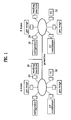
- FIG. 1 illustrates a layout of home networks sharing a communication line in accordance with a preferred embodiment of the present invention
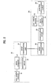
- FIG. 2 illustrates a block diagram of a detail system of the appliances and the power line communication adapters in FIG. 1
- FIGS. 3A - 3C illustrate structures of communication packets transmitted in FIG. 1
- FIG. 4 illustrates a flow chart showing the steps of a method for setting a code for identifying multiple home networks of the present invention
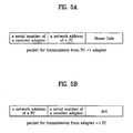
- FIGS. 5A - 5C illustrate structures of communication packets transmitted in FIG. 4
- FIG. 6 illustrates a flow chart showing the steps of a method for identifying multiple home networks in accordance with a preferred embodiment of the present invention.
- FIG. 1 There are home network systems sharing a communication line of a power line of the present invention illustrated in FIG. 1.
- a home 'A' and a home 'B' have home networks constructed respectively to share a communication line of a power line, with home appliances 10 in each of the homes connected to the power line through a power line communication adapters 20.
- a PC 30 in each home serves as a controller for controlling the network.
- FIG. 2 A detailed system of FIG. 1 is illustrated in FIG. 2.
- each appliance 10 includes a non-volatile memory 11, a microcomputer 12 for operation of the appliance and communication control, a serial communication port 14 for transmission/reception of data
- each of the adapters 20 includes a non-volatile memory 21, a serial communication port 22 for communication with the serial communication port 14 of the appliance 10, a communication circuit 23, a communication control microcomputer 24, and a power line communication module 25 for enabling data communication through the power line.
- the serial communication port 14 of each of the appliances 10 and the serial communication port 22 of the adapter 20 are connected, and the power line communication module 25 of each of the adapters 20 is connected to the power line.
- FIGS. 3A - 3C Structures of transmission packets of the appliances of the foregoing home networks are illustrated in FIGS. 3A - 3C.
- a transmission packet from the appliance 10 to the adapter 20 includes an 'STX (starting code)', 'a receiver address', 'message to be transmitted', a 'CRC' (an error check code), and 'ETX (termination code)'.
- a transmission packet from the adapter 20 to the power line includes a 'house code', an 'STX', a 'receiver address', a 'transmitter address', a 'message to be transmitted', a 'CRC', and an 'ETX'.
- a transmission packet from the adapter 20 to the appliance 10 includes an 'STX', a 'receiver address', a 'transmitter address', a 'message to be transmitted', a 'CRC', and an 'ETX'. That is, the 'house code' is added only when a transmission is made through the power line.
- a user or a service man from a manufacturer connects the adapter 20 to an appliance 10 (S41).
- a program for setting a house code is put into operation in a PC 30 (S42).
- the program may be downloaded through Internet, or provided in a form of a CD or a diskette.
- a serial number of the user fitted adapter 200 is provided to the operative program for setting a house code (S43).
- the program for setting a house code makes an automatic access to a house code managing site (S44).
- the accessed house code managing site assigns its own house code not in use at the present time, and transfers to the PC 30 (S45).
- the house code setting program in the PC 30 constructs a packet including 'a receiver adapter serial number' defining a receiver address, 'a PC network address' defining a transmitter address, and 'the house code' assigned from the managing site. (S46).
- the house code setting program transfers the packet to the adapter 20 (S47).
- reception of 'ACK' from the adapter 20 is determined (S48), and a determination that the house code setting is finished is made and the process is terminated if the 'ACK' is received, or the transfer of the packet is repeated if no 'ACK' is received.
- the adapter 20 upon reception of the packet as shown in FIG. 5A, the adapter 20 responds with a packet constructed to include 'a PC network address' defining a receiver address, 'a receiver adapter serial number' defining a transmitter address, and the 'ACK' as shown in FIG. 5B.
- Each of the adapters 20 determines if a packet is received through a power line (S61). If the packet is received as a result of the determination (S61), each of the adapters 20 compares the house code in the packet to the house code set in the setting of the house code (S62).
- conformity of the house codes is determined (S63) as a result of the comparison (S62), and the packet is transferred to a connected appliance 20 if the house codes are in conformity (S64).
- the method for identifying multiple home networks having a common communication line can identify a home network in multiple home networks having a common communication line effectively by a simple setting and an algorithm addition without additional hardware, whereby permitting to make an efficient and reliable communication.
Landscapes
- Engineering & Computer Science (AREA)
- Automation & Control Theory (AREA)
- Computer Networks & Wireless Communication (AREA)
- Signal Processing (AREA)
- Computing Systems (AREA)
- Small-Scale Networks (AREA)
- Selective Calling Equipment (AREA)
- Data Exchanges In Wide-Area Networks (AREA)
- Cable Transmission Systems, Equalization Of Radio And Reduction Of Echo (AREA)
Claims (3)
- Méthode d'identification de réseaux domestiques multiples ayant chacun une pluralité d'appareils ménagers connectés à des adaptateurs respectifs et un contrôleur de réseau, dans laquelle une adresse est attribuée à chaque appareil ménager, et au moins deux réseaux domestiques partagent une ligne de communication, la méthode comprenant les étapes consistant à :définir un code maison pour chacun des adaptateurs connectés aux appareils ménagers pour identifier les réseaux domestiques ; etrecevoir un paquet comprenant le code maison sur la ligne de communication au niveau des adaptateurs ;comparer un code maison défini pour chacun des adaptateurs au code maison inclus dans le paquet ; etfaire comprendre à un des adaptateurs que le paquet est destiné à l'adaptateur en question si les deux codes maison sont en conformité suite à la comparaison, et transférer le paquet à un des appareils ménagers connectés à celui-ci,caractérisée en ce que l'étape consistant à définir un code maison comprend les étapes consistant à :exécuter un programme de définition de code maison dans un contrôleur de réseau,fournir un numéro de série de l'adaptateur et donner accès au site de gestion de codes maison sur Internet dans le programme,recevoir un code maison propre attribué à partir du site de gestion de codes maison et transférer ledit code maison à l'adaptateur correspondant, etpermettre le stockage par l'adaptateur du code maison sur une zone de mémoire correspondante.
- Méthode selon la revendication 1, dans laquelle l'étape consistant à fournir un numéro de série de l'adaptateur et à donner accès à un site de gestion de codes maison sur Internet dans le programme comprend l'étape consistant à établir un accès automatique au site de gestion de codes maison une fois que le numéro de série pour l'adaptateur est fourni.
- Méthode selon la revendication 1, comprenant en outre l'étape dans laquelle les adaptateurs ignorent le paquet reçu si les deux codes maison ne sont pas en conformité suite à la comparaison.
Applications Claiming Priority (3)
| Application Number | Priority Date | Filing Date | Title |
|---|---|---|---|
| KR10-2002-0017807A KR100425129B1 (ko) | 2002-04-01 | 2002-04-01 | 통신선로를 공유하는 다수의 홈 네트워크 구분방법 |
| KR2002017807 | 2002-04-01 | ||
| PCT/KR2002/000654 WO2003084143A1 (fr) | 2002-04-01 | 2002-04-10 | Procede de separation de reseaux multiples familiaux |
Publications (3)
| Publication Number | Publication Date |
|---|---|
| EP1523828A1 EP1523828A1 (fr) | 2005-04-20 |
| EP1523828A4 EP1523828A4 (fr) | 2005-09-14 |
| EP1523828B1 true EP1523828B1 (fr) | 2007-01-03 |
Family
ID=28673047
Family Applications (1)
| Application Number | Title | Priority Date | Filing Date |
|---|---|---|---|
| EP02717207A Expired - Lifetime EP1523828B1 (fr) | 2002-04-01 | 2002-04-10 | Procede de separation de reseaux domestiques multiples |
Country Status (8)
| Country | Link |
|---|---|
| US (1) | US20050256944A1 (fr) |
| EP (1) | EP1523828B1 (fr) |
| KR (1) | KR100425129B1 (fr) |
| CN (1) | CN1623298A (fr) |
| AU (1) | AU2002248068A1 (fr) |
| DE (1) | DE60217413T2 (fr) |
| GB (1) | GB2402585B (fr) |
| WO (1) | WO2003084143A1 (fr) |
Families Citing this family (7)
| Publication number | Priority date | Publication date | Assignee | Title |
|---|---|---|---|---|
| KR100504610B1 (ko) * | 2002-12-06 | 2005-08-01 | 엘지전자 주식회사 | 홈 네트워크 시스템의 홈 코드 설정방법 |
| WO2005094191A2 (fr) * | 2004-03-31 | 2005-10-13 | Lg Electronics, Inc. | Procede de traitement de données pour couche de réseau |
| US20080130687A1 (en) * | 2004-03-31 | 2008-06-05 | Lg Electronics Inc. | Data Receiving Method and Transferring Method for Data Link Layer |
| JP5094004B2 (ja) * | 2005-10-20 | 2012-12-12 | パナソニック株式会社 | データ中継装置及びデータ中継方法 |
| US7680906B2 (en) * | 2006-02-22 | 2010-03-16 | Microsoft Corporation | Configuring devices using context histories |
| CN104796853B (zh) * | 2015-05-19 | 2018-07-06 | 北京子清智创科技有限公司 | 一种设备间通信系统及方法 |
| US10186254B2 (en) | 2015-06-07 | 2019-01-22 | Apple Inc. | Context-based endpoint detection |
Family Cites Families (6)
| Publication number | Priority date | Publication date | Assignee | Title |
|---|---|---|---|---|
| GB8307149D0 (en) * | 1983-03-15 | 1983-04-20 | Emi Ltd | Data distribution network |
| KR0128169B1 (ko) * | 1993-12-31 | 1998-04-15 | 김광호 | 사용자 제어 정의 기능을 가지는 가정 자동화 시스템 |
| US5949779A (en) * | 1997-05-08 | 1999-09-07 | Ericsson, Inc. | Multiprotocol adaptor for communication between CEBus devices and remote controllers over an ATM-based broadband access network |
| US6058355A (en) * | 1997-06-30 | 2000-05-02 | Ericsson Inc. | Automatic power outage notification via CEBus interface |
| JP3980131B2 (ja) * | 1997-09-25 | 2007-09-26 | 松下電器産業株式会社 | 制御装置、初期設定可能通信システム、及び初期設定可能通信システムの制御方法 |
| US20020011923A1 (en) * | 2000-01-13 | 2002-01-31 | Thalia Products, Inc. | Appliance Communication And Control System And Appliance For Use In Same |
-
2002
- 2002-04-01 KR KR10-2002-0017807A patent/KR100425129B1/ko not_active Expired - Fee Related
- 2002-04-10 DE DE60217413T patent/DE60217413T2/de not_active Expired - Lifetime
- 2002-04-10 EP EP02717207A patent/EP1523828B1/fr not_active Expired - Lifetime
- 2002-04-10 WO PCT/KR2002/000654 patent/WO2003084143A1/fr not_active Ceased
- 2002-04-10 GB GB0419617A patent/GB2402585B/en not_active Expired - Fee Related
- 2002-04-10 AU AU2002248068A patent/AU2002248068A1/en not_active Abandoned
- 2002-04-10 US US10/506,431 patent/US20050256944A1/en not_active Abandoned
- 2002-04-10 CN CNA028286391A patent/CN1623298A/zh active Pending
Also Published As
| Publication number | Publication date |
|---|---|
| EP1523828A4 (fr) | 2005-09-14 |
| DE60217413D1 (de) | 2007-02-15 |
| GB2402585B (en) | 2006-03-01 |
| KR20030079047A (ko) | 2003-10-10 |
| CN1623298A (zh) | 2005-06-01 |
| GB0419617D0 (en) | 2004-10-06 |
| EP1523828A1 (fr) | 2005-04-20 |
| US20050256944A1 (en) | 2005-11-17 |
| WO2003084143A1 (fr) | 2003-10-09 |
| AU2002248068A1 (en) | 2003-10-13 |
| DE60217413T2 (de) | 2007-10-18 |
| KR100425129B1 (ko) | 2004-03-30 |
| GB2402585A (en) | 2004-12-08 |
Similar Documents
| Publication | Publication Date | Title |
|---|---|---|
| EP1569419B1 (fr) | Méthode d'attribution d'adresses à une pluralité de dispositifs dans un réseau et dans un système correspondant | |
| KR100424297B1 (ko) | 가전기기 제어시스템 및 그 동작방법 | |
| KR100565487B1 (ko) | 가전기기 네트워크 시스템 및 그 동작방법 | |
| KR100437042B1 (ko) | 가전기기 네트워크 시스템 및 그 제어방법 | |
| US8145767B2 (en) | Sensor device, server node, sensor network system, method of establishing communication path, control program, and storage medium | |
| US7430591B2 (en) | Methods and arrangements for configuring functional networks | |
| KR100420526B1 (ko) | 가전기기 네트워크 시스템 및 그 제어방법 | |
| KR20040032644A (ko) | 홈 네트워크 시스템의 동작방법 | |
| US7158485B2 (en) | Method for joining node into subnet of power line communication network, electronic appliance connected to subnet, and communication module used in electronic appliance | |
| EP1523828B1 (fr) | Procede de separation de reseaux domestiques multiples | |
| WO2003079610A1 (fr) | Procede de confirmation de l'etat de connexion d'un appareil domestique dans un systeme reseau domestique | |
| US7539779B2 (en) | Method for separating multiple home networks | |
| EP1570576B1 (fr) | Procede de reglage de code de bureau local d'un systeme de reseau local | |
| US20050265245A1 (en) | Method of transferring data in a local household network | |
| EP1011225A1 (fr) | Procede de gestion de reseau et procede de selection d'un gestionnaire de reseau | |
| KR100565524B1 (ko) | 홈네트워크 시스템 및 그 동작방법 | |
| KR100381171B1 (ko) | 가전기기 제어시스템 및 그 동작방법 | |
| KR100412357B1 (ko) | 가전기기 네트워킹 시스템 및 그 방법 | |
| KR100565499B1 (ko) | 마스터기기의 플러그인 방법 | |
| KR100495058B1 (ko) | 전력라인 통신을 이용한 가전기기 네트워크 시스템 및 그동작방법 | |
| KR100424319B1 (ko) | 가전기기 네트워크 시스템의 제어방법 | |
| AU2002248066B2 (en) | Method for separating multiple home networks | |
| AU2002248066A1 (en) | Method for separating multiple home networks |
Legal Events
| Date | Code | Title | Description |
|---|---|---|---|
| PUAI | Public reference made under article 153(3) epc to a published international application that has entered the european phase |
Free format text: ORIGINAL CODE: 0009012 |
|
| 17P | Request for examination filed |
Effective date: 20050204 |
|
| AK | Designated contracting states |
Kind code of ref document: A1 Designated state(s): AT BE CH CY DE DK ES FI FR GB GR IE IT LI LU MC NL PT SE TR |
|
| AX | Request for extension of the european patent |
Extension state: AL LT LV MK RO SI |
|
| A4 | Supplementary search report drawn up and despatched |
Effective date: 20050801 |
|
| GRAP | Despatch of communication of intention to grant a patent |
Free format text: ORIGINAL CODE: EPIDOSNIGR1 |
|
| RIN1 | Information on inventor provided before grant (corrected) |
Inventor name: CHOI, HWAN JONG Inventor name: LIM, JEONG HYUN Inventor name: LEE, KOON SEOK Inventor name: BAEK, SEUNG MYUN |
|
| GRAS | Grant fee paid |
Free format text: ORIGINAL CODE: EPIDOSNIGR3 |
|
| GRAA | (expected) grant |
Free format text: ORIGINAL CODE: 0009210 |
|
| AK | Designated contracting states |
Kind code of ref document: B1 Designated state(s): DE FR |
|
| RAP1 | Party data changed (applicant data changed or rights of an application transferred) |
Owner name: LG ELECTRONICS INC. |
|
| REF | Corresponds to: |
Ref document number: 60217413 Country of ref document: DE Date of ref document: 20070215 Kind code of ref document: P |
|
| ET | Fr: translation filed | ||
| PLBE | No opposition filed within time limit |
Free format text: ORIGINAL CODE: 0009261 |
|
| STAA | Information on the status of an ep patent application or granted ep patent |
Free format text: STATUS: NO OPPOSITION FILED WITHIN TIME LIMIT |
|
| 26N | No opposition filed |
Effective date: 20071005 |
|
| PGFP | Annual fee paid to national office [announced via postgrant information from national office to epo] |
Ref country code: FR Payment date: 20140312 Year of fee payment: 13 |
|
| PGFP | Annual fee paid to national office [announced via postgrant information from national office to epo] |
Ref country code: DE Payment date: 20140312 Year of fee payment: 13 |
|
| REG | Reference to a national code |
Ref country code: DE Ref legal event code: R119 Ref document number: 60217413 Country of ref document: DE |
|
| PG25 | Lapsed in a contracting state [announced via postgrant information from national office to epo] |
Ref country code: DE Free format text: LAPSE BECAUSE OF NON-PAYMENT OF DUE FEES Effective date: 20151103 |
|
| REG | Reference to a national code |
Ref country code: FR Ref legal event code: ST Effective date: 20151231 |
|
| PG25 | Lapsed in a contracting state [announced via postgrant information from national office to epo] |
Ref country code: FR Free format text: LAPSE BECAUSE OF NON-PAYMENT OF DUE FEES Effective date: 20150430 |