EP1523842B1 - Contenant, notamment boitier de partie de telephone mobile et procede de production d'une partie de boitier - Google Patents
Contenant, notamment boitier de partie de telephone mobile et procede de production d'une partie de boitier Download PDFInfo
- Publication number
- EP1523842B1 EP1523842B1 EP03787687A EP03787687A EP1523842B1 EP 1523842 B1 EP1523842 B1 EP 1523842B1 EP 03787687 A EP03787687 A EP 03787687A EP 03787687 A EP03787687 A EP 03787687A EP 1523842 B1 EP1523842 B1 EP 1523842B1
- Authority
- EP
- European Patent Office
- Prior art keywords
- enclosure
- base body
- seal
- housing
- produced
- Prior art date
- Legal status (The legal status is an assumption and is not a legal conclusion. Google has not performed a legal analysis and makes no representation as to the accuracy of the status listed.)
- Expired - Lifetime
Links
- 238000000034 method Methods 0.000 title claims description 6
- 238000004519 manufacturing process Methods 0.000 claims abstract description 20
- 238000001746 injection moulding Methods 0.000 claims abstract description 14
- 239000003566 sealing material Substances 0.000 claims abstract description 11
- 239000000463 material Substances 0.000 claims description 30
- 238000007789 sealing Methods 0.000 claims description 29
- 229920003023 plastic Polymers 0.000 claims description 14
- 239000004033 plastic Substances 0.000 claims description 13
- 229920002725 thermoplastic elastomer Polymers 0.000 claims description 7
- 239000000428 dust Substances 0.000 description 8
- 229920001169 thermoplastic Polymers 0.000 description 7
- 239000004416 thermosoftening plastic Substances 0.000 description 7
- 239000000126 substance Substances 0.000 description 5
- 239000013013 elastic material Substances 0.000 description 4
- 229920001971 elastomer Polymers 0.000 description 4
- 238000003825 pressing Methods 0.000 description 4
- 239000007787 solid Substances 0.000 description 3
- 238000003860 storage Methods 0.000 description 3
- 150000001875 compounds Chemical class 0.000 description 2
- 239000000806 elastomer Substances 0.000 description 2
- 235000013305 food Nutrition 0.000 description 2
- 238000002347 injection Methods 0.000 description 2
- 239000007924 injection Substances 0.000 description 2
- 238000003754 machining Methods 0.000 description 2
- 238000002844 melting Methods 0.000 description 2
- 230000008018 melting Effects 0.000 description 2
- 230000035515 penetration Effects 0.000 description 2
- 239000000853 adhesive Substances 0.000 description 1
- 230000001070 adhesive effect Effects 0.000 description 1
- 238000004873 anchoring Methods 0.000 description 1
- 230000007613 environmental effect Effects 0.000 description 1
- 239000002360 explosive Substances 0.000 description 1
- 239000011888 foil Substances 0.000 description 1
- 239000007788 liquid Substances 0.000 description 1
- 238000000465 moulding Methods 0.000 description 1
- 229920005615 natural polymer Polymers 0.000 description 1
- 230000003287 optical effect Effects 0.000 description 1
- 235000011837 pasties Nutrition 0.000 description 1
- 239000003348 petrochemical agent Substances 0.000 description 1
- 229920002742 polystyrene-block-poly(ethylene/propylene) -block-polystyrene Polymers 0.000 description 1
- 239000007779 soft material Substances 0.000 description 1
- 229920006132 styrene block copolymer Polymers 0.000 description 1
- 229920001935 styrene-ethylene-butadiene-styrene Polymers 0.000 description 1
- 229920001059 synthetic polymer Polymers 0.000 description 1
- XLYOFNOQVPJJNP-UHFFFAOYSA-N water Substances O XLYOFNOQVPJJNP-UHFFFAOYSA-N 0.000 description 1
- 238000003466 welding Methods 0.000 description 1
Images


Classifications
-
- H—ELECTRICITY
- H04—ELECTRIC COMMUNICATION TECHNIQUE
- H04M—TELEPHONIC COMMUNICATION
- H04M1/00—Substation equipment, e.g. for use by subscribers
- H04M1/02—Constructional features of telephone sets
- H04M1/0202—Portable telephone sets, e.g. cordless phones, mobile phones or bar type handsets
- H04M1/026—Details of the structure or mounting of specific components
- H04M1/0262—Details of the structure or mounting of specific components for a battery compartment
-
- B—PERFORMING OPERATIONS; TRANSPORTING
- B29—WORKING OF PLASTICS; WORKING OF SUBSTANCES IN A PLASTIC STATE IN GENERAL
- B29C—SHAPING OR JOINING OF PLASTICS; SHAPING OF MATERIAL IN A PLASTIC STATE, NOT OTHERWISE PROVIDED FOR; AFTER-TREATMENT OF THE SHAPED PRODUCTS, e.g. REPAIRING
- B29C45/00—Injection moulding, i.e. forcing the required volume of moulding material through a nozzle into a closed mould; Apparatus therefor
- B29C45/16—Making multilayered or multicoloured articles
- B29C45/1615—The materials being injected at different moulding stations
- B29C45/162—The materials being injected at different moulding stations using means, e.g. mould parts, for transferring an injected part between moulding stations
-
- B—PERFORMING OPERATIONS; TRANSPORTING
- B29—WORKING OF PLASTICS; WORKING OF SUBSTANCES IN A PLASTIC STATE IN GENERAL
- B29C—SHAPING OR JOINING OF PLASTICS; SHAPING OF MATERIAL IN A PLASTIC STATE, NOT OTHERWISE PROVIDED FOR; AFTER-TREATMENT OF THE SHAPED PRODUCTS, e.g. REPAIRING
- B29C45/00—Injection moulding, i.e. forcing the required volume of moulding material through a nozzle into a closed mould; Apparatus therefor
- B29C45/16—Making multilayered or multicoloured articles
- B29C45/1676—Making multilayered or multicoloured articles using a soft material and a rigid material, e.g. making articles with a sealing part
-
- B—PERFORMING OPERATIONS; TRANSPORTING
- B29—WORKING OF PLASTICS; WORKING OF SUBSTANCES IN A PLASTIC STATE IN GENERAL
- B29C—SHAPING OR JOINING OF PLASTICS; SHAPING OF MATERIAL IN A PLASTIC STATE, NOT OTHERWISE PROVIDED FOR; AFTER-TREATMENT OF THE SHAPED PRODUCTS, e.g. REPAIRING
- B29C33/00—Moulds or cores; Details thereof or accessories therefor
- B29C33/20—Opening, closing or clamping
-
- B—PERFORMING OPERATIONS; TRANSPORTING
- B29—WORKING OF PLASTICS; WORKING OF SUBSTANCES IN A PLASTIC STATE IN GENERAL
- B29C—SHAPING OR JOINING OF PLASTICS; SHAPING OF MATERIAL IN A PLASTIC STATE, NOT OTHERWISE PROVIDED FOR; AFTER-TREATMENT OF THE SHAPED PRODUCTS, e.g. REPAIRING
- B29C45/00—Injection moulding, i.e. forcing the required volume of moulding material through a nozzle into a closed mould; Apparatus therefor
- B29C45/03—Injection moulding apparatus
- B29C45/04—Injection moulding apparatus using movable moulds or mould halves
- B29C45/06—Injection moulding apparatus using movable moulds or mould halves mounted on a turntable, i.e. on a rotating support having a rotating axis parallel to the mould opening, closing or clamping direction
- B29C45/062—Injection moulding apparatus using movable moulds or mould halves mounted on a turntable, i.e. on a rotating support having a rotating axis parallel to the mould opening, closing or clamping direction carrying mould halves co-operating with fixed mould halves
-
- B—PERFORMING OPERATIONS; TRANSPORTING
- B29—WORKING OF PLASTICS; WORKING OF SUBSTANCES IN A PLASTIC STATE IN GENERAL
- B29L—INDEXING SCHEME ASSOCIATED WITH SUBCLASS B29C, RELATING TO PARTICULAR ARTICLES
- B29L2031/00—Other particular articles
- B29L2031/34—Electrical apparatus, e.g. sparking plugs or parts thereof
- B29L2031/3431—Telephones, Earphones
- B29L2031/3437—Cellular phones
Definitions
- the invention relates to a container having a first container base body and a second container base body.
- the invention relates to a container which constitutes a housing for a telephone mobile part.
- the invention further relates to a method for producing a housing part for a telephone mobile part.
- GB 2 345 818 is a portable telecommunications component, a mobile handset described. This consists of a plurality of components, in particular a keypad, a display panel, an upper housing and a lower housing and a battery part. The individual components are assembled by placing the keypad in the upper housing, then inserting the component containing the display into the upper housing and then screwing the lower housing to the upper housing. The lower housing contains a recess into which the Battrerieteil is introduced.
- the GB 2 345 818 A There are different ways of. Screwing or nesting of the upper and lower housing on.
- the international patent application WO 01/083381 A1 relates to a mobile phone with a housing upper shell with integrated keyboard and display.
- a transparent plastic housing is produced by injecting a plastic into a mold in an injection molding process and enters into a connection with a film in such a way that a housing upper shell is formed.
- the plastic housing in this case has a first area, which serves as a display window, and a second area with at least one recess with means for forwarding a keystroke.
- the foil covers at least the second area and realized above the recess located a key, which is characterized in particular by a printed on the film character and wherein the means a keystroke is forwarded.
- the German patent specification DE 196 18 453 C1 relates to a 2-component plastic housing, in particular for a key with remote control for a motor vehicle.
- the housing is made so that an elastic material is injected in an upper housing part, which serves to hold a printed circuit board.
- the elastic material also serves as a seal against a lower part of the housing, which seal lies in the interior of the lower part.
- German patent application DE 196 30 966 A1 relates to a method for producing a screen-like housing part for radio devices, in particular a handset of a radio device.
- a conductive seal is applied to a lower shell, which seal serves for contacting a printed circuit board.
- the seal only seals the lower shell from the PCB.
- German patent application DE 44 28 335 A1 relates to a plastic housing for an electrical module with a housing body and a bottom plate.
- a seal which may also be produced in two-color injection molding process, serves to seal an opening in the housing body as well as in one of the embodiments shown as a seal between the housing part and the bottom plate.
- the German utility model DE 298 19 434 U1 describes a housing with a shielding seal for an electromagnetically shielded recording of electronic components, in particular a mobile telephone device.
- a sealing profile is applied, which is pasty in the initial state or is foamed liquid and becomes an elastically cured plastic.
- the cured one Sealing material does not adhere to the upper part.
- a sealing strip for the sealing of a slot of a sliding plate is described, wherein on the sealing strip a seal is cast.
- the material of the strip is harder than the material of the seal, which may be a soft, rubber-elastic material with a Shore hardness of 50 ,.
- the international application WO 00/08722 A1 relates to a mobile telephone with a moisture-resistant electrical contact.
- the mobile telephone has a housing with an upper housing part and a lower housing part which, when joined together, form a shell which surrounds the components contained therein.
- the moisture-resistant electrical contact is disposed outside the housing and penetrates the lower housing part, wherein it is connected by a spring arm with the electrical circuits of the mobile phone. By melting the electrical contact in the lower housing parts a moisture-impermeable connection between the material of the lower housing part and the electrical contact is given.
- the Japanese publication JP 6297497 describes a manufacturing method of a seal which consists of rubber-elastic material and is fixed integrally with the side wall of a housing. In this case, a cavity is formed around the side wall, is filled in the molten thermoplastic elastomer.
- Housing or containers for electrical equipment or containers and storage containers for example, for the storage of perishable food or weather-sensitive objects, increased demands may be made in terms of tightness against moisture, dust or other.
- the first container base body may be a so-called upper shell and the second container base body may be a so-called lower shell or vice versa.
- the object of the invention is to provide a container with at least two container base bodies, wherein a sealing function is provided between the two container base bodies.
- a container in particular a housing for a telephone mobile part, with a first container base body of a first base material comprising a first edge and a second container base body of a second base material comprising a second edge.
- the two container base bodies abut one another along the first edge and the second edge and there have a seal made of a sealing material, which is firmly connected to the first container body, and sealingly abuts the second edge, wherein the sealing material consists of an elastically deformable material ,
- the container may preferably be a housing for receiving electrical devices or mechanical components, components or devices.
- this may be a mobile phone, ie a mobile terminal, a cordless phone also for use in industrial environments, such as repair and production facilities, painters up in explosive environment such as in petrochemicals.
- Other possible containers may be for calculators, electronic appointment schedulers, sensor housings, watches and others.
- a corresponding housing may in this case have a length of a few to several tens of centimeters, a width of also a few centimeters to a few tens of centimeters and correspondingly have a height of a few centimeters to also a few tens of centimeters.
- Typical dimensions for mobile devices and cordless telephones are in the order of 5 to 20 centimeters long, 2 to 5 centimeters wide and 1 to 3 centimeters high.
- the seal itself can in this case run along the edge or circumference of a corresponding housing and have a width of less than one millimeter to a few millimeters and a height of less than one millimeter.
- the first container base body may be a so-called upper shell and the second container base body a so-called lower shell or vice versa.
- a tightly connected to the first edge, in particular conclusive and integrally connected to the first container body seal already causes a tightness towards the first container body.
- the seal is an integral part of the first edge.
- a tightness to the second container base body is achieved by the elastic deformability of the material of the seal, in which when a collision of the first edge with the second edge, the sealing material is elastically deforming applied to the second edge and thus largely a seal against ingress of moisture, dust or similar guarantees.
- Such a container is therefore suitable for receiving sensitive objects such as electronic devices or mechanical devices as well as foods that are to be protected against environmental influences such as moisture, water, chemicals, dust or mechanical influences.
- the seal By a firm connection of the seal with the first container base body, the number of loose or mutually displaceable elements for producing a sealing connection between the first container base body and the second container base body is reduced to these two container base body. It is therefore not necessary to provide a separate seal, for example in the form of a sealing ring and to provide corresponding brackets, grooves or other labor-consuming to manufacture bracket devices. It also reduces the number of container parts to be kept, which simplifies both the storage and the handling of the container parts.
- the seal is on an outer side of the first container base body, which, for example, an upper shell of a Housing a mobile phone may be arranged.
- first container base body which, for example, an upper shell of a Housing a mobile phone may be arranged.
- the seal preferably protrudes on the outside beyond the first container base body in the direction of the second container base body.
- a labyrinth seal can preferably be formed from the first container base body, the seal and the second container base body.
- the second container base body is undercut in a kind of a step and the first container base body protrudes into this stage, so that the first container base body and the second container base body overlap.
- the second container base body seen from outside to inside behind the seal has an increase in the direction of the first container base body, whereby a narrow channel between the first container base body and the second container body can be formed inside the housing behind the seal.
- the second edge against which the seal rests is made of a harder material than the seal itself.
- the second container base body may preferably be made of a single material, which is also the material of the second edge at the same time. It is also possible to make the second edge also from a different material than the rest of the second container body.
- the first container body may also preferably be made of a harder material than the seal.
- the first container base body made of a hard plastic and the seal made of a soft plastic.
- the first container base body is produced together with the seal in the so-called 2-color injection molding process.
- 2-color injection molding also known as 2-component injection molding
- plastic materials for individual components and functional elements of different materials and hardness are produced in one processing cycle, which can save considerable assembly costs.
- Components or elements produced in this way are, depending on the choice of materials, resistant to external influences and are distinguished by a high bond strength.
- An adhesive force achieved in the interface region can be brought about by a chemical bond or mechanical anchoring.
- a solid molecular compound is usually obtained by melting or welding.
- the 2-component injection molding process is based on the force and / or positive connection of two plastic components with the general different properties to form an integrated molding.
- the 2-component injection molding process is particularly suitable for components which are intended to have both rigid and elastic regions, as a result of which different functions can be fulfilled at the same time.
- the material for the seal is preferably a thermoplastic elastomer.
- Elastomers are understood as meaning synthetic or natural polymers with rubber-elastic behavior, as indicated, for example, in Rompps-Chemielexikon 8th edition, page 1082, Franksche Verlags Stuttgart, 1981.
- Thermoplastic elastomers can be obtained, for example, from Kraiburg TBE GmbH, Teplitzer Strasse 20, D-84478 Waldkraiburg.
- Thermoplastic elastomers may be those based on SEBS and SEPS (filtered styrene block copolymers).
- the first base material of the first container base body is preferably a thermoplastic application.
- the second base material of the second container base body preferably also consists of a thermoplastic.
- Thermoplastics are according to the above Rompps-Chemielexikon at ordinary temperature, in particular room temperature hard or even brittle plastics, which soften reversibly when heat is applied and mechanically easily deformed.
- thermoplastics are defined in the German Industrial Standard (DIN) 7724.
- the sealing material of the seal preferably has a Shore hardness between 50 and 60. According to the above Rompp Chemical Dictionary, according to the German Industrial Standard (DIN) 53505, the Shore hardness is determined by the resistance of elastomers, rubber and rubber against the penetration of a truncated cone.
- a housing for a mobile telephone part which may be a handset of a cordless telephone or a mobile telephone
- a third container base body which serves to receive a replaceable electrical power source, in particular a battery or a rechargeable battery.
- the third container base abuts in this case either on the first container base body or on the second container base body and is sealed with a further elastic seal against the corresponding container body.
- the further seal is preferably applied either on the third Be Zellnisgruhd emotions itself or on this abutting container base body, ie the first and the second container base body.
- the seal may be of the same type as the seal between the second and first container base body, in particular it may form an integral part in a two-color injection molding process with the third container base body or the first or second container base body associated therewith.
- the object directed to a method for producing a housing part, in particular for a mobile telephone part is achieved by a method in which an elastic seal is applied in a two-color injection molding process.
- a hard component is sprayed onto a solid tool and the hard component is molded with a first counter-tool movable in a demolding direction.
- a soft component forming the seal is sprayed onto the hard component and formed with a second counter-tool, which is moved in the same removal direction as the first counter-tool for removal from the mold.
- a turntable tool is used on the at least two housing parts of the same Sort of be edited.
- a housing part being processed is transferred from, a first machining operation, the application of the hard component, in a second machining operation of the application of the soft component.
- a turntable tool can thus reduce the production time of a variety of housing parts of the same kind.
- the hard component of the housing part produced and simultaneously applied to a previously prepared hard component of the housing part, the soft component at another point of the turntable tool.
- the housing part with hard component and soft component is removed and rotated the housing part with the hard component in the position in which in the next processing time, the soft component is applied.
- the soft component is applied to the hard component when the hard component is still warm.
- Warm in this context means that the hard component still has a temperature at which a bonding of the soft component and the hard component takes place, in particular a chemical molecule bond is formed which would be stronger than at normal room temperature.
- the container in particular a housing for a telephone handset, and the method for producing a housing part are explained in more detail by way of example.
- FIG. 1 is a perspective view of a container 1, here a housing 1 a telephone mobile part, shown.
- the housing 1 has a first container base body 2, which is made of a hard component 8, on which is applied to a first edge 3, corresponding essentially to the outer circumference of the first container base body 2, an elastically deformable soft component 4.
- the first container base 2 which is an upper shell 2, openings for keys 5, a display 6 and a speaker 7 are provided.
- the hard component 8 is made of a first base material, in particular a thermoplastic.
- the housing 1 has a second container base body 9, a lower shell. This lower shell 9 has a second edge 10 which abuts with the first edge 3 of the upper shell 2 together.
- the second edge 10 thereby comes into direct contact with the soft component 4, the seal 4, so that the housing 1 is sealed against the ingress of dust and moisture.
- the seal 4 At the upper shell 2 sloped off.
- Side is on the lower shell 9, a further soft component 11 at least in a region for receiving a third container base body 12, a battery or Akkumulatorteils applied. From the housing 1 also protrudes a transmitting and receiving antenna 13 out.
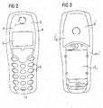
- FIG. 2 is an alternative embodiment of a first container base body 2, an upper shell of a cordless Teleforimobilteils in a plan view of the outside, shown.
- the upper shell 2 also has openings for keys 5, a display 6, a speaker 7 and a microphone 14.
- a first edge 3 of the first container base body 2 a soft material is applied to the outside, which, as in FIG. 4 is shown schematically, in the form of a ridge on the one hard component 8 forming the first base material 'away from the outside, towards a second container base body 9 (see FIG. 3 ).
- the soft component 4 is also applied to the outside of the upper shell 2 in the form of a wide band, where it has no sealing function. It can serve here as an additional optical element.
- FIG. 4 shows an upper shell 2, according to FIG. 2 in a plan view on the inside.
- the hard component 8 on the outer circumference on a circumferential, inwardly directed outer web 14. Still further outside around this outer web 14 around the soft component 4, thereby forming a sealing web 27.
- the outer web 14 and the inwardly projecting seal 4 are spaced apart, for example by less than 1 mm or up to a few mm.
- hard component recess 24 and the soft component recess 25 of the sealing ridge 27 and the outer web 14 are formed, which are spaced by a corresponding recess of each other. It is both possible that the sealing ridge 27 projects beyond the outer web 14 or vice versa or both at the same level.
- this locking webs 15 and guide cylinder 16 serves to engage in corresponding to the lower shell 9 attached counter-ridges and cylinders for fixing and holding together the upper shell 2 with the lower shell 9 to form a housing.
- a channel of a labyrinth seal 30 is formed between the sealing web 14 and the second edge 10 (see FIG Fig. 8 ).
- a channel of a labyrinth seal 30 is formed between the sealing web 14 and the second edge 10 (see FIG Fig. 8 ).
- an even narrower channel is formed between the upper shell 2 and lower shell 9 of a labyrinth seal 30.
- FIG. 3 is a lower shell 9, matching the upper shell 2, according to FIG. 2 shown in a plan view of the outside.
- the lower shell 9 has a receiving region 17 for an accumulator part, not shown.
- the receiving region 17 is bordered by a further soft component 11, which is applied to the hard component 18 (second base material) of the lower shell 9.
- the further soft component 11 forms a seal between the lower shell 9 and the accumulator part, not shown.
- the hard component 8 and 18 are preferably made of the same base material, in particular a thermoplastic.
- Soft component 4, 11 are also preferably made of a same sealing material, in particular a thermoplastic elastomer.
- FIG. 5 is schematically shown in a plan view of a turntable tool 19, which is rotatable about an axis of rotation 20.
- the turntable tool 19 has two similar tool structures for producing identical housing parts (see FIG. 6, FIG. 7 ).
- This in FIG. 5 Turntable tool 19 shown schematically serves to produce a first container base body 2, an upper shell of a housing of a telephone mobile part.
- Such a first container base body 2 has analogous to those in FIG. 1 and 2 shown upper shell 2 openings for buttons 5, display 6, speaker 7 on.
- the turntable tool 19 is for producing the upper shell 2, not shown, a movable counter-tool, which is displaceable in the direction of the axis of rotation 20 and is not shown assigned.
- the turntable tool 19 represents the solid mold half, the counter tool, not shown, the movable mold half.
- the production of the upper shell 2 is carried out in two steps, wherein in a first step after merging the turntable tool 19 and the movable counter-tool 22 (see FIG. 6 ) is injected by means of the injection molding a hard component between the turntable tool 19 and the first movable counter-tool 22.
- the tool structure 21 of the turntable tool 19 has a hard component recess 24 and the adjoining housing contour structure 26.
- the hard component 8 injected between the turntable tool 19 and the first movable counter tool 22 assumes the shape of the upper shell 2 in accordance with the housing contour structure 26, wherein the hard component recess 24 has penetrated into the hard component recess 24
- the first movable counter-tool 22 is raised in the direction of the axis of rotation 20 where effected by demolding of the hard component 8 in the vertical direction.
- the turntable tool 19 is rotated by 180 ° so that the hard component 8 can now be surrounded by a second movable counter-tool 23 (see FIG FIG. 7 ).
- the resulting between the hard component 8 and the second movable tool 23 cavity is ejected with a soft component 4.
- This soft component 4 flows into a soft component recess 25 of the turntable tool 19 and receives its contour through the hard component 8.
- the soft component is in this case sprayed onto an outer side 29 of the hard component.
- the soft component 4, which may be a thermoplastic elastomer is sprayed onto the hard component 8, which may be a thermoplastic, even if the hard component 8 still has such a high temperature that a good chemical bond between the hard component 8 and the Soft component 4 takes place.
- the second movable counter-tool 23 is also lifted in the direction of the axis of rotation 20, so that also takes a demolding of the soft component 4 in the vertical direction (see FIG. 7 ). Due to the soft component recess 25, the soft component 4 also forms a kind of web, which is suitable by the elastic deformability of the soft component 4 as a seal against a lower shell of the housing for a mobile phone part. (Seal 27 analogous to FIGS. 8 and 9 ).
- the sealing ridge 27 and the outer web 14 are formed, which are spaced from each other by a corresponding recess. It is both possible that the sealing ridge 27 projects beyond the outer web 14 or vice versa or both at the same level.
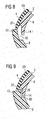
- FIGS. 8 and 9 show two different embodiments of a first container base 2 and a second container base body 9 adjacent thereto in a section of a longitudinal section.
- the first container base body 2 in each case has a hard component 8 with an outer web 14.
- a soft component 4 serving as a seal is applied, which forms a sealing ridge 27, which is adjacent to the outer ridge 14 and is elastically deformable due to the material property of the soft component 4.
- the soft component 4 rests sealingly against the edge 10 of the second container base body 9 with the sealing web 27.
- the second container base body 9 has an additional sealing web 28, which projects into the space between the sealing web 27 and the outer web 14.
Landscapes
- Engineering & Computer Science (AREA)
- Mechanical Engineering (AREA)
- Manufacturing & Machinery (AREA)
- Signal Processing (AREA)
- Telephone Set Structure (AREA)
- Casings For Electric Apparatus (AREA)
- Injection Moulding Of Plastics Or The Like (AREA)
Abstract
Claims (14)
- Contenant (1), en particulier boîtier pour une partie de téléphone mobile, avec un premier corps de base de contenant (2) en une première matière de base (8) comprenant un premier bord (3) et avec un deuxième corps de base de contenant (9) en une deuxième matière de base (18) comprenant un deuxième bord (10), lesquels butent l'un contre l'autre le long du premier bord (3) et du deuxième bord (10), et avec une garniture d'étanchéité (4) en une matière d'étanchéité,
laquelle est reliée de manière fixe au premier corps de base de contenant (2), et dont la matière d'étanchéité se compose d'une matière élastiquement déformable, caractérisé en ce que la garniture d'étanchéité est disposée sur un côté extérieur (29) du premier corps de base de contenant (2), et en ce qu'elle repose de manière étanche contre le deuxième bord (10). - Contenant (1) selon la revendication 1,
la garniture d'étanchéité (4) sur le premier côté extérieur (29) dépassant vers l'extérieur du premier corps de base de contenant (2) en direction du deuxième corps de base de contenant (9). - Contenant (1) selon l'une quelconque des revendications précédentes, une garniture en labyrinthe (30) étant formée à partir du premier corps de base de contenant (2), de la garniture d'étanchéité (4) et du deuxième corps de base de contenant (9).
- Contenant (1) selon l'une quelconque des revendications précédentes, le deuxième bord (10) contre lequel repose la garniture d'étanchéité (4) se composant d'une matière plus dure que celle de la garniture d'étanchéité (4).
- Contenant (1) selon l'une quelconque des revendications précédentes, le premier corps de base d'étanchéité (2) étant fabriqué à partir d'une matière synthétique dure et la garniture d'étanchéité (4) étant fabriquée à partir d'une matière synthétique plus tendre.
- Contenant (1) selon la revendication 5, le premier corps de base de contenant (2) étant fabriqué avec la garniture d'étanchéité (4) selon un procédé de moulage par injection avec deux couleurs.
- Contenant (1) selon l'une quelconque des revendications précédentes, la garniture d'étanchéité (4) se composant d'un élastomère thermoplastique.
- Contenant (1) selon l'une quelconque des revendications précédentes, la première matière de base (8) du premier corps de base de contenant (2) se composant d'une matière thermoplastique.
- Contenant (1) selon l'une quelconque des revendications précédentes, la matière d'étanchéité présentant une dureté Shore comprise entre 50-60.
- Contenant (1) selon l'une quelconque des revendications précédentes, pour l'hébergement de composants électriques, électroniques ou mécaniques ou d'aliments.
- Contenant (1) selon l'une quelconque des revendications précédentes, lequel est un boîtier pour une partie de téléphone mobile et présente un troisième corps de base de contenant (12) servant à héberger une source de courant électrique interchangeable, le troisième corps de base de contenant (12) butant contre le premier corps de base de contenant (2) ou le deuxième corps de base de contenant (9) et étant colmaté par rapport à celui-ci à l'aide d'une autre garniture d'étanchéité élastique (11), moyennant quoi l'autre garniture d'étanchéité (11) est appliquée sur le troisième corps de base de contenant (12) ou sur le deuxième corps de base de contenant (9) et/ou sur le premier corps de base de contenant (2).
- Procédé de fabrication d'un élément de boîtier (2, 9) pour une partie de téléphone mobile, avec une garniture d'étanchéité élastique (4) selon un procédé de moulage par injection avec deux couleurs, moyennant quoi lors d'une première étape de fabrication, un composant dur est moulé par injection sur un outil fixe, moyennant quoi le composant dur (8) est formé avec un premier outil opposé (22) mobile dans une direction de déformation, caractérisé en ce qu'au cours d'une deuxième étape de fabrication, un composant tendre formant la garniture d'étanchéité (4) est moulé par injection sur le côté extérieur (29) du composant dur (8) et est formé avec une deuxième outil opposé (23) que l'on fait bouger dans la même direction de déformation que le premier outil opposé (22).
- Procédé selon la revendication 12, un plateau tournant (19) étant utilisé, sur lequel deux éléments de boîtier sont usinés grâce à la rotation, l'un pour l'application du composant dur (8) et l'autre pour l'application du composant tendre (4).
- Procédé selon l'une quelconque des revendications 12 et 13, le composant tendre (4) étant appliqué sur le composant dur (8), lorsque ce dernier est encore chaud.
Applications Claiming Priority (3)
| Application Number | Priority Date | Filing Date | Title |
|---|---|---|---|
| DE10232947 | 2002-07-19 | ||
| DE10232947A DE10232947A1 (de) | 2002-07-19 | 2002-07-19 | Behältnis, insbesondere Gehäuse für ein Telefonmobilteil sowie Verfahren zur Herstellung eines Gehäuseteils |
| PCT/DE2003/002431 WO2004017614A1 (fr) | 2002-07-19 | 2003-07-18 | Contenant, notamment boitier de partie de telephone mobile et procede de production d'une partie de boitier |
Publications (2)
| Publication Number | Publication Date |
|---|---|
| EP1523842A1 EP1523842A1 (fr) | 2005-04-20 |
| EP1523842B1 true EP1523842B1 (fr) | 2011-01-26 |
Family
ID=29796473
Family Applications (1)
| Application Number | Title | Priority Date | Filing Date |
|---|---|---|---|
| EP03787687A Expired - Lifetime EP1523842B1 (fr) | 2002-07-19 | 2003-07-18 | Contenant, notamment boitier de partie de telephone mobile et procede de production d'une partie de boitier |
Country Status (8)
| Country | Link |
|---|---|
| US (1) | US7551949B2 (fr) |
| EP (1) | EP1523842B1 (fr) |
| JP (1) | JP2005533459A (fr) |
| KR (1) | KR20050027117A (fr) |
| CN (1) | CN1669292A (fr) |
| AU (1) | AU2003250790A1 (fr) |
| DE (2) | DE10232947A1 (fr) |
| WO (1) | WO2004017614A1 (fr) |
Families Citing this family (28)
| Publication number | Priority date | Publication date | Assignee | Title |
|---|---|---|---|---|
| EP1677587B1 (fr) * | 2004-12-30 | 2008-10-08 | Sony Ericsson Mobile Communications AB | Boîtier étanche, joint d'étanchéité et procédé de montage et de démontage du boîtier étanche |
| US20060175370A1 (en) | 2005-01-03 | 2006-08-10 | Michel Arney | Removable mounting post assembly for a carrying case |
| DE102005036037B4 (de) | 2005-08-01 | 2025-02-27 | Robert Bosch Gmbh | Messgerät |
| WO2007037405A1 (fr) * | 2005-09-29 | 2007-04-05 | Kyocera Corporation | Dispositif de terminal portable |
| US20070138920A1 (en) * | 2005-12-16 | 2007-06-21 | Symbol Technologies, Inc. | Methods and apparatus for a rugged mobile device housing |
| KR100751943B1 (ko) | 2006-03-28 | 2007-08-24 | 엘지전자 주식회사 | 외장 케이스 및 이를 갖는 휴대 단말기 |
| CN101106875B (zh) * | 2006-07-12 | 2010-05-12 | 英华达(南京)科技有限公司 | 行动装置翻盖的制造方法 |
| JP5250200B2 (ja) * | 2006-11-24 | 2013-07-31 | 富士通株式会社 | 携帯端末装置 |
| US20090075761A1 (en) * | 2007-09-18 | 2009-03-19 | Joseph Balardeta | Golf gps device and system |
| KR100934641B1 (ko) * | 2008-05-26 | 2009-12-31 | 주식회사 신양엔지니어링 | 이동통신단말기 전면케이스 조립용 지그 어셈블리 |
| KR101561301B1 (ko) * | 2008-10-22 | 2015-10-19 | 삼성전자주식회사 | 사출물 제작 방법 |
| KR101563366B1 (ko) * | 2009-02-04 | 2015-10-26 | 삼성전자주식회사 | 이물질 차단 장치를 구비한 휴대용 전자 장치 |
| US8755852B2 (en) | 2009-02-06 | 2014-06-17 | Speculative Product Design, Llc | One piece co-formed exterior hard shell case with an elastomeric liner for mobile electronic devices |
| KR101025794B1 (ko) * | 2009-07-14 | 2011-04-04 | (주)블루버드 소프트 | 모바일 단말기 |
| CA2771098A1 (fr) | 2009-08-12 | 2011-02-17 | Uncommon, LLC | Etui de transport et de protection compose de deux pieces |
| DE102009047148A1 (de) * | 2009-11-25 | 2011-05-26 | Huf Hülsbeck & Fürst Gmbh & Co. Kg | Mobile Vorrichtung |
| CN105892582A (zh) | 2010-10-18 | 2016-08-24 | 苹果公司 | 带有暴露区域的便携式计算机 |
| GB2486400B (en) * | 2010-11-20 | 2016-02-10 | Pulse Medical Technologies Ltd | Device for generating magnetic fields |
| JP5963295B2 (ja) * | 2011-12-08 | 2016-08-03 | 日本メクトロン株式会社 | 防水機能付蓋部材 |
| US20140092536A1 (en) * | 2012-09-25 | 2014-04-03 | Speculative Product Design, Llc | Case utilizing reinforced film for in-mold labeling |
| US9143181B1 (en) * | 2014-06-06 | 2015-09-22 | Valor Communication, Inc. | Verge hybrid cell phone protector case |
| JP6315276B2 (ja) * | 2014-11-19 | 2018-04-25 | 株式会社デンソー | 携帯機 |
| GB2538562B (en) | 2015-05-22 | 2018-04-18 | Dyson Technology Ltd | A hand held appliance |
| JP6587179B2 (ja) * | 2015-09-18 | 2019-10-09 | パナソニックIpマネジメント株式会社 | 電気機器 |
| US10418746B2 (en) * | 2016-11-22 | 2019-09-17 | Ford Global Technologies, Llc | Charge port assembly and molding method |
| HUE073379T2 (hu) * | 2018-06-22 | 2026-01-28 | Hoffmann La Roche | Orvostechnikai eszköz és eljárás összeszerelésére és szétszerelésére |
| US11522571B2 (en) | 2019-10-28 | 2022-12-06 | Speculative Product Design, Llc | Mobile device case with bonded soft resin insert and shell |
| CN111923318A (zh) * | 2020-08-03 | 2020-11-13 | 歌尔股份有限公司 | 发声装置及其成型方法 |
Family Cites Families (34)
| Publication number | Priority date | Publication date | Assignee | Title |
|---|---|---|---|---|
| US4225970A (en) * | 1978-11-24 | 1980-09-30 | Motorola, Inc. | Splash proof portable two-way data terminal/radio |
| US4418839A (en) * | 1981-06-29 | 1983-12-06 | Emerson Electric Co. | Meter controlled dispensing apparatus |
| US4418830A (en) * | 1981-08-27 | 1983-12-06 | Motorola, Inc. | Moisture and dust seal arrangement for a portable radio or the like |
| EP0180383A3 (fr) * | 1984-10-26 | 1987-06-03 | Aronkasei Co., Limited | Méthode de fabrication pour boítiers ayant une structure à deux couches |
| US4711361A (en) * | 1986-05-01 | 1987-12-08 | Motorola, Inc. | Interlocking module housing |
| EP0474247B1 (fr) * | 1990-09-07 | 1998-12-16 | Nec Corporation | Circuit de détermination du montant de décalage dans une calculation à virgule flottante utilisant peu de matériel et étant opérable à grande vitesse |
| US5526526A (en) * | 1992-02-27 | 1996-06-11 | Acr Electronics, Inc. | Survival radio |
| JP3320140B2 (ja) | 1993-04-20 | 2002-09-03 | 信越ポリマー株式会社 | 封止容器の製造方法 |
| US5386084A (en) * | 1993-07-22 | 1995-01-31 | Ii Morrow Inc. | Electronic device enclosure |
| DE9311554U1 (de) * | 1993-08-03 | 1993-10-28 | Behr France S.A.R.L., Rouffach | Dichtleiste für einen Schiebesteller |
| EP0685894B1 (fr) * | 1994-06-03 | 1997-10-22 | Kokusai Electric Co., Ltd. | Dispositif électronique protégé contre les projections d'eau |
| DE4428335A1 (de) * | 1994-08-10 | 1996-02-15 | Duerrwaechter E Dr Doduco | Kunststoffgehäuse für ein elektrisches Modul |
| WO1997008926A2 (fr) | 1995-08-31 | 1997-03-06 | Siemens Aktiengesellschaft | Procede de fabrication d'un boitier avec effet de blindage pour des appareils de radiocommunication |
| DE19630966A1 (de) * | 1995-08-31 | 1997-03-06 | Siemens Ag | Verfahren zur Herstellung eines Gehäuseteils mit Schirmwirkung für Funkgeräte |
| DE19618453A1 (de) | 1996-05-08 | 1996-10-24 | Manfred Klingbeil | Tiefkühlkostdatum-Alarmwächter |
| US5896453A (en) * | 1997-04-24 | 1999-04-20 | Ericsson, Inc. | Circuitry protection device |
| DE19718453C1 (de) * | 1997-04-30 | 1998-09-03 | Siemens Ag | Zwei-Komponenten-Kunststoffgehäuse |
| JP3168946B2 (ja) | 1997-06-27 | 2001-05-21 | 岩崎通信機株式会社 | 携帯用電子機器の電池蓋防水構造 |
| US5970402A (en) * | 1997-08-09 | 1999-10-19 | Lucent Technologies, Inc. | Radio card |
| US6078792A (en) * | 1997-09-12 | 2000-06-20 | Ericsson, Inc. | Water-exposure protection for a mobile radio communication device |
| DE29819434U1 (de) * | 1998-02-09 | 1999-02-18 | Kahl, Helmut, 12307 Berlin | Gehäuse |
| US6227872B1 (en) * | 1998-08-05 | 2001-05-08 | Ericsson Inc. | Moisture resistant electrical connector for a cellular telephone |
| EP1020947A3 (fr) * | 1998-12-22 | 2000-10-04 | Nokia Mobile Phones Ltd. | Méthode de produuction d'un corps d'antenne pour téléphone et combiné téléphonique comprenant une antenne interne |
| JP2000209314A (ja) * | 1999-01-13 | 2000-07-28 | Nec Corp | 携帯用通信機 |
| JP2000299725A (ja) | 1999-04-13 | 2000-10-24 | Matsushita Electric Ind Co Ltd | 携帯電話機 |
| DE19934707C1 (de) | 1999-07-23 | 2001-02-15 | Siemens Ag | Gehäuseoberschale für Geräte mit integrierter Tastatur und Display |
| FR2808269B1 (fr) * | 2000-04-28 | 2002-12-20 | Andre Gabet | Procede et dispositif pour ameliorer le gout d'une eau potable |
| DE10063696A1 (de) * | 2000-12-20 | 2002-07-18 | Siemens Ag | Verfahren zur Herstellung eines Gehäuses eines mobilen Kommunikations-Endgerätes, Gehäuse und mobiles Kommunikations-Endgerät |
| US7711400B2 (en) * | 2000-12-29 | 2010-05-04 | Vertu Limited | Casing |
| US7758787B2 (en) * | 2002-06-07 | 2010-07-20 | Intier Automotive Inc. | Multi-shot injection molded component and method of manufacture |
| WO2004016055A1 (fr) * | 2002-08-05 | 2004-02-19 | Koninklijke Philips Electronics N.V. | Produit electronique, corps et procede de fabrication |
| US20040198243A1 (en) * | 2002-08-13 | 2004-10-07 | Tony Tasy | Mobile phone with a replaceable face panel |
| USPP15129P2 (en) * | 2003-02-25 | 2004-08-31 | Sakata Seed Corporation | Portulaca plant named ‘Yubi Primrose’ |
| US7404884B2 (en) * | 2003-04-25 | 2008-07-29 | Siemens Water Technologies Holding Corp. | Injection bonded articles and methods |
-
2002
- 2002-07-19 DE DE10232947A patent/DE10232947A1/de not_active Withdrawn
-
2003
- 2003-07-18 CN CN03817258.5A patent/CN1669292A/zh active Pending
- 2003-07-18 WO PCT/DE2003/002431 patent/WO2004017614A1/fr not_active Ceased
- 2003-07-18 US US10/521,389 patent/US7551949B2/en not_active Expired - Fee Related
- 2003-07-18 KR KR1020057001015A patent/KR20050027117A/ko not_active Ceased
- 2003-07-18 DE DE50313440T patent/DE50313440D1/de not_active Expired - Lifetime
- 2003-07-18 JP JP2004528392A patent/JP2005533459A/ja active Pending
- 2003-07-18 AU AU2003250790A patent/AU2003250790A1/en not_active Abandoned
- 2003-07-18 EP EP03787687A patent/EP1523842B1/fr not_active Expired - Lifetime
Also Published As
| Publication number | Publication date |
|---|---|
| JP2005533459A (ja) | 2005-11-04 |
| AU2003250790A1 (en) | 2004-03-03 |
| KR20050027117A (ko) | 2005-03-17 |
| DE10232947A1 (de) | 2004-01-29 |
| CN1669292A (zh) | 2005-09-14 |
| US7551949B2 (en) | 2009-06-23 |
| EP1523842A1 (fr) | 2005-04-20 |
| DE50313440D1 (de) | 2011-03-10 |
| WO2004017614A1 (fr) | 2004-02-26 |
| US20060166711A1 (en) | 2006-07-27 |
Similar Documents
| Publication | Publication Date | Title |
|---|---|---|
| EP1523842B1 (fr) | Contenant, notamment boitier de partie de telephone mobile et procede de production d'une partie de boitier | |
| EP0633585B1 (fr) | Boîtier pour appareils de télécommunication électrique | |
| DE102005043893B4 (de) | Drahtloser Schlüsselanhänger für Fahrzeuge | |
| DE60033714T2 (de) | Bedienungstafel mit blattförmigen Tasteneinheit und Verfahren zu deren Herstellung | |
| DE60034162T2 (de) | Schalttafel für elektronische Geräte und Verfahren zu seiner Herstellung | |
| DE60022308T2 (de) | Kunststoffgehäuse zum Erreichen von Kompatibilität zwischen der Luftpermeabilität und der Wasserdichtheit, Giessform zur Herstellung eines solchen Gehäuses und Verfahren zum Herstellen eines solchen Gehäuses | |
| DE3144084C2 (de) | Verfahren zur Herstellung einer für ein Drucktastenfeld geeigneten Kontaktmatte | |
| DE69628573T2 (de) | Batteriepack mit trennschalter | |
| EP1163415B1 (fr) | Profil d'etancheite pour etancheifier un dispositif de fermeture actionne par energie exterieure | |
| DE112004000492B4 (de) | Abdeckung für einen Tastenschalter | |
| DE4207786A1 (de) | Tastenfeld und verfahren zur herstellung eines tastenfeldes | |
| DE19607970A1 (de) | Batteriepack und Verfahren zu seiner Herstellung | |
| DE19715536A1 (de) | Griffgehäuse mit eingebautem Schalter und Verfahren zu dessen Herstellung | |
| EP1343618B1 (fr) | Procede de production d'un boitier destine a un terminal de communication mobile, un tel boitier et terminal de communication mobile | |
| DE60001113T2 (de) | Leiterplatteneinkapselung | |
| DE69603787T2 (de) | Verfahren zum Verbinden eines Bedienungspanels einer elektronischen Vorrichtung | |
| EP1054420A1 (fr) | Clavier pour appareil électrique ou électronique et procédé de fabrication | |
| DE19819287A1 (de) | Elektrisches Bauteil | |
| EP1110365B1 (fr) | Partie superieure de boitier pour un terminal de telecommunication | |
| EP0615265B1 (fr) | Partie de boîtier avec interrupteur à bouton poussoir et méthode de fabrication | |
| EP1570631B1 (fr) | Dispositif d'entree, notamment pour un telephone portable, module comportant un tel dispositif d'entree, telephone portable et procede de production correspondant | |
| EP2537197B1 (fr) | Unité d'alimentation en énergie pour un appareil électrique | |
| DE10109361A1 (de) | Gehäuseteil für ein elektrisches Gerät und Verfahren zu seiner Herstellung | |
| EP0891602A1 (fr) | Boitier pour circuit electronique utilisable dans une carte electronique, et procede de fabrication d'une telle carte | |
| DE10152719C1 (de) | Verfahren zum Einschäumen von Kabeln |
Legal Events
| Date | Code | Title | Description |
|---|---|---|---|
| PUAI | Public reference made under article 153(3) epc to a published international application that has entered the european phase |
Free format text: ORIGINAL CODE: 0009012 |
|
| 17P | Request for examination filed |
Effective date: 20041222 |
|
| AK | Designated contracting states |
Kind code of ref document: A1 Designated state(s): AT BE BG CH CY CZ DE DK EE ES FI FR GB GR HU IE IT LI LU MC NL PT RO SE SI SK TR |
|
| AX | Request for extension of the european patent |
Extension state: AL LT LV MK |
|
| DAX | Request for extension of the european patent (deleted) | ||
| RBV | Designated contracting states (corrected) |
Designated state(s): DE FR GB IT SE |
|
| 17Q | First examination report despatched |
Effective date: 20060914 |
|
| GRAP | Despatch of communication of intention to grant a patent |
Free format text: ORIGINAL CODE: EPIDOSNIGR1 |
|
| GRAS | Grant fee paid |
Free format text: ORIGINAL CODE: EPIDOSNIGR3 |
|
| GRAA | (expected) grant |
Free format text: ORIGINAL CODE: 0009210 |
|
| AK | Designated contracting states |
Kind code of ref document: B1 Designated state(s): DE FR GB IT SE |
|
| REG | Reference to a national code |
Ref country code: GB Ref legal event code: FG4D Free format text: NOT ENGLISH |
|
| REF | Corresponds to: |
Ref document number: 50313440 Country of ref document: DE Date of ref document: 20110310 Kind code of ref document: P |
|
| REG | Reference to a national code |
Ref country code: DE Ref legal event code: R096 Ref document number: 50313440 Country of ref document: DE Effective date: 20110310 |
|
| REG | Reference to a national code |
Ref country code: SE Ref legal event code: TRGR |
|
| RAP2 | Party data changed (patent owner data changed or rights of a patent transferred) |
Owner name: SIEMENS ENTERPRISE COMMUNICATIONS GMBH & CO. KG |
|
| PLBE | No opposition filed within time limit |
Free format text: ORIGINAL CODE: 0009261 |
|
| STAA | Information on the status of an ep patent application or granted ep patent |
Free format text: STATUS: NO OPPOSITION FILED WITHIN TIME LIMIT |
|
| 26N | No opposition filed |
Effective date: 20111027 |
|
| REG | Reference to a national code |
Ref country code: DE Ref legal event code: R097 Ref document number: 50313440 Country of ref document: DE Effective date: 20111027 |
|
| REG | Reference to a national code |
Ref country code: GB Ref legal event code: 746 Effective date: 20130418 |
|
| REG | Reference to a national code |
Ref country code: DE Ref legal event code: R084 Ref document number: 50313440 Country of ref document: DE Effective date: 20130226 |
|
| REG | Reference to a national code |
Ref country code: FR Ref legal event code: CD Owner name: UNIFY GMBH & CO. KG, DE Effective date: 20150209 |
|
| REG | Reference to a national code |
Ref country code: FR Ref legal event code: PLFP Year of fee payment: 13 |
|
| PGFP | Annual fee paid to national office [announced via postgrant information from national office to epo] |
Ref country code: DE Payment date: 20150722 Year of fee payment: 13 Ref country code: GB Payment date: 20150724 Year of fee payment: 13 |
|
| PGFP | Annual fee paid to national office [announced via postgrant information from national office to epo] |
Ref country code: FR Payment date: 20150730 Year of fee payment: 13 Ref country code: SE Payment date: 20150724 Year of fee payment: 13 |
|
| PGFP | Annual fee paid to national office [announced via postgrant information from national office to epo] |
Ref country code: IT Payment date: 20150728 Year of fee payment: 13 |
|
| REG | Reference to a national code |
Ref country code: GB Ref legal event code: 732E Free format text: REGISTERED BETWEEN 20151210 AND 20151216 |
|
| REG | Reference to a national code |
Ref country code: DE Ref legal event code: R119 Ref document number: 50313440 Country of ref document: DE |
|
| REG | Reference to a national code |
Ref country code: SE Ref legal event code: EUG |
|
| GBPC | Gb: european patent ceased through non-payment of renewal fee |
Effective date: 20160718 |
|
| PG25 | Lapsed in a contracting state [announced via postgrant information from national office to epo] |
Ref country code: FR Free format text: LAPSE BECAUSE OF NON-PAYMENT OF DUE FEES Effective date: 20160801 Ref country code: DE Free format text: LAPSE BECAUSE OF NON-PAYMENT OF DUE FEES Effective date: 20170201 Ref country code: SE Free format text: LAPSE BECAUSE OF NON-PAYMENT OF DUE FEES Effective date: 20160719 |
|
| REG | Reference to a national code |
Ref country code: FR Ref legal event code: ST Effective date: 20170331 |
|
| PG25 | Lapsed in a contracting state [announced via postgrant information from national office to epo] |
Ref country code: GB Free format text: LAPSE BECAUSE OF NON-PAYMENT OF DUE FEES Effective date: 20160718 |
|
| PG25 | Lapsed in a contracting state [announced via postgrant information from national office to epo] |
Ref country code: IT Free format text: LAPSE BECAUSE OF NON-PAYMENT OF DUE FEES Effective date: 20160718 |