EP1523933A1 - Endoscope - Google Patents
Endoscope Download PDFInfo
- Publication number
- EP1523933A1 EP1523933A1 EP04024384A EP04024384A EP1523933A1 EP 1523933 A1 EP1523933 A1 EP 1523933A1 EP 04024384 A EP04024384 A EP 04024384A EP 04024384 A EP04024384 A EP 04024384A EP 1523933 A1 EP1523933 A1 EP 1523933A1
- Authority
- EP
- European Patent Office
- Prior art keywords
- endoscope
- distal end
- optical member
- frame member
- insertion section
- Prior art date
- Legal status (The legal status is an assumption and is not a legal conclusion. Google has not performed a legal analysis and makes no representation as to the accuracy of the status listed.)
- Granted
Links
- 230000003287 optical effect Effects 0.000 claims abstract description 105
- 238000003780 insertion Methods 0.000 claims abstract description 67
- 230000037431 insertion Effects 0.000 claims abstract description 67
- 238000005286 illumination Methods 0.000 claims abstract description 57
- 230000002093 peripheral effect Effects 0.000 claims description 55
- 239000002184 metal Substances 0.000 claims description 14
- 238000003466 welding Methods 0.000 claims description 9
- 238000002844 melting Methods 0.000 claims description 6
- 230000008018 melting Effects 0.000 claims description 6
- 238000010438 heat treatment Methods 0.000 claims description 3
- 238000012545 processing Methods 0.000 claims description 3
- 238000003754 machining Methods 0.000 claims 1
- 239000000155 melt Substances 0.000 claims 1
- 239000000853 adhesive Substances 0.000 description 19
- 230000001070 adhesive effect Effects 0.000 description 19
- 239000000835 fiber Substances 0.000 description 10
- 238000000034 method Methods 0.000 description 6
- 238000012986 modification Methods 0.000 description 6
- 230000004048 modification Effects 0.000 description 6
- 239000000463 material Substances 0.000 description 4
- 238000004659 sterilization and disinfection Methods 0.000 description 4
- 238000005452 bending Methods 0.000 description 3
- 230000001954 sterilising effect Effects 0.000 description 3
- 238000013461 design Methods 0.000 description 2
- 239000007769 metal material Substances 0.000 description 2
- 229910001220 stainless steel Inorganic materials 0.000 description 2
- 239000010935 stainless steel Substances 0.000 description 2
- 238000004140 cleaning Methods 0.000 description 1
- 238000005336 cracking Methods 0.000 description 1
- 230000007423 decrease Effects 0.000 description 1
- 230000000694 effects Effects 0.000 description 1
- 238000005530 etching Methods 0.000 description 1
- 239000011521 glass Substances 0.000 description 1
- 239000007788 liquid Substances 0.000 description 1
- 238000004519 manufacturing process Methods 0.000 description 1
- 229910052594 sapphire Inorganic materials 0.000 description 1
- 239000010980 sapphire Substances 0.000 description 1
- 229910000679 solder Inorganic materials 0.000 description 1
- 239000000126 substance Substances 0.000 description 1
- XLYOFNOQVPJJNP-UHFFFAOYSA-N water Substances O XLYOFNOQVPJJNP-UHFFFAOYSA-N 0.000 description 1
Images


Classifications
-
- A—HUMAN NECESSITIES
- A61—MEDICAL OR VETERINARY SCIENCE; HYGIENE
- A61B—DIAGNOSIS; SURGERY; IDENTIFICATION
- A61B1/00—Instruments for performing medical examinations of the interior of cavities or tubes of the body by visual or photographical inspection, e.g. endoscopes; Illuminating arrangements therefor
- A61B1/00064—Constructional details of the endoscope body
- A61B1/00071—Insertion part of the endoscope body
- A61B1/0008—Insertion part of the endoscope body characterised by distal tip features
- A61B1/00096—Optical elements
-
- A—HUMAN NECESSITIES
- A61—MEDICAL OR VETERINARY SCIENCE; HYGIENE
- A61B—DIAGNOSIS; SURGERY; IDENTIFICATION
- A61B1/00—Instruments for performing medical examinations of the interior of cavities or tubes of the body by visual or photographical inspection, e.g. endoscopes; Illuminating arrangements therefor
- A61B1/00064—Constructional details of the endoscope body
- A61B1/0011—Manufacturing of endoscope parts
-
- A—HUMAN NECESSITIES
- A61—MEDICAL OR VETERINARY SCIENCE; HYGIENE
- A61B—DIAGNOSIS; SURGERY; IDENTIFICATION
- A61B1/00—Instruments for performing medical examinations of the interior of cavities or tubes of the body by visual or photographical inspection, e.g. endoscopes; Illuminating arrangements therefor
- A61B1/012—Instruments for performing medical examinations of the interior of cavities or tubes of the body by visual or photographical inspection, e.g. endoscopes; Illuminating arrangements therefor characterised by internal passages or accessories therefor
Definitions
- the present invention relates to an endoscope in which a rigid portion body on the distal end portion of an elongated insertion section to be inserted into a body cavity has mounting holes in which optical members of an observation optical system and an illumination optical system are mounted.
- Jpn. Pat. Appln. KOKAI Publication No. 2002-85326 for example, a technique is described for fixing an optical member to a cover member that is provided independently of a rigid portion body on the distal end portion of an insertion section of an endoscope.
- the cover member having an opening is located on the distal end portion of the insertion section to hold the distal end face of the optical member in an exposed state.
- the diameter of the opening of the cover member on its one side is larger than the diameter on the other side, that is, the opening is tapered.
- the surface of the cover member which has the larger opening diameter is opposed to the proximal end side of the insertion section.
- the optical member has a tapered shape such that it is mounted in the tapered opening. Thus, the optical member can be prevented from slipping off the cover member.
- the rigid portion body of the endoscope described above is formed having an opening in which an integrated unit that combines the optical member and a frame on the distal end portion of the insertion section is located.
- the optical member is firmly soldered or brazed to the frame.
- the cover member has a small hole in its distal end face. The diameter of the small hole is less than the largest diameter of the integrated unit. A large hole having a larger diameter than that of the small hole is formed in a position a little closer to the proximal end side of the insertion section than the distal end face of the cover member.
- the small and large holes are tapered and linked together.
- the optical member of the unit is tapered to mount the tapered cover member. If the integrated unit is inserted into the cover member from its proximal end side and fixed the optical member is prevented from being disengaged in a forward direction from the distal end face of the cover member.
- the strength of securing of the optical member to the distal end portion of the insertion section is improved so that the endoscope is repeatedly subjected to autoclave sterilization.
- various prescribed methods of cleaning, disinfection, and sterilization are recommended by endoscope manufacturers in consideration of good chemical, thermal, and mechanical loads for safe design.
- there is an increasing demand for the assurance of the safety of endoscopes such that the optical member cannot be disengaged from the distal end portion of the insertion section during use even if the endoscope used is wrongly treated through not complying with the manufacturer's prescriptions.
- the cover member having the opening with a diameter less than the largest diameter of the optical member must be provided independently of the rigid portion body on the distal end portion of the insertion section. Accordingly, components of the distal end portion of the insertion section increase slightly in number, so that assembly is complicated.
- an optical member e.g., integrated unit that combines an optical window member and a frame member
- an optical member that is larger in diameter than the opening of the rigid portion body must be mounted into the body from its proximal end side. It is necessary to provide the rigid portion body with a large hole through which the optical member can be passed, as a result of which the outside diameter of the distal end portion of the insertion section increases. Since the optical member cannot be mounted from the distal end side of the rigid portion body, moreover, assembling the distal end portion of the insertion section is troublesome.
- the present invention has been made in view of these problems, and its object is to provide an endoscope which uses fewer components and enjoys higher assembly properties and in which optical members or a unit including optical members is prevented from slipping off a rigid portion body on the distal end portion of its insertion section even if the endoscope is wrongly cleaned, disinfected, or sterilized as a result of a user not complying with the manufacturer's prescriptions.
- an endoscope including an elongated insertion section which has a distal end portion and is inserted into a body cavity.
- the insertion section has a rigid portion body on the distal end portion.
- the rigid portion body has at least one mounting hole in which each of optical members of an observation optical system and an illumination optical system is mounted.
- a binding portion which mechanically restricts the optical member with respect to the rigid portion body is provided on at least a part of the boundary between the mounting hole and the optical member mounted in the mounting hole.
- FIGS. 1 to 2C A first embodiment will first be described with reference to FIGS. 1 to 2C.
- an endoscope 10 includes an elongated insertion section 12, which can be inserted into a body cavity, and an operation section 14 on the proximal end portion of the insertion section 12.
- the insertion section 12 has a rigid portion 22, a bending portion 24, and a flexible tube 26.
- the rigid portion 22 is located on the distal end portion of the insertion section 12.
- the bending portion 24 is provided on the proximal end portion of the rigid portion 22 and can be bent in a desired direction by manipulating the operation section 14.
- the flexible tube 26 has its distal and proximal end portions coupled to the proximal end portion of the bending portion 24 and the operation section 14, respectively.
- the rigid portion 22 includes a rigid portion body 32.
- the body 32 is formed of a stainless steel material or the like that is a chemically stable metal material.
- the body 32 is formed having, for example, first to fourth circular holes 34, 36, 38 and 40 that extend parallel to the axial direction of the insertion section 12.
- an optical member is located in each of the first to third holes 34, 36 and 38. More specifically, an observation optical system is located as an optical member in the first hole 34, and illumination optical systems are arranged in the second and third holes 36 and 38, individually.
- a cylindrical frame member 44 is in contact with the inner peripheral surface of the first circular hole 34.
- the former is bonded to the latter with an adhesive.
- the frame member 44 is formed of a stainless steel material or the like that is a chemically stable metal material.
- a substantially disc-shaped objective cover lens 46 for use as an optical window member is mounted in the frame member 44. The lens 46 is bonded to the frame member 44 with the adhesive.
- a substantially disc-shaped illumination lens 52 for use as an optical window member is mounted in the inner peripheral surface of each of the second and third circular holes 36 and 38.
- the illumination lens 52 and the rigid portion body 32, like the objective cover lens 46 and the frame member 44, are bonded to each other with the adhesive.
- the fourth circular hole 40 shown in FIG. 2A is formed as an opening portion on one end side of a channel through which an instrument (not shown) or the like is passed from the side of the operation section 14. More specifically, the hole 40 communicates with the interior of the insertion section 12, an opening portion 40a (see FIG. 1) on the other end side opens in the operation section 14. If necessary, the instrument or the like may be passed through the channel via the opening portion 40a of the operation section 14 and projected from the fourth first hole 40, or water (liquid) or air (gas) may be fed into a patient's body through the channel.
- the objective cover lens 46 which is situated ahead of a group of objective lenses of the observation optical system, and the illumination lenses 52 of the illumination optical systems are exposed from the distal end face of the rigid portion body 32.
- the lenses 46 and 52 and other lenses are formed of a stable material, such as glass or sapphire.
- a constriction is formed on the proximal end face of the objective cover lens 46 by etching or the like.
- a first convex lens 56 is affixed to the proximal end face of the lens 46 with a transparent adhesive in a manner such that it is convex toward the proximal end of the rigid portion body 32.
- the lenses 46 and 56 are mounted in a body in the pipe-shaped frame member 44.
- the outer peripheral surface of a member that integrally combines the lenses 46 and 56 and the inner peripheral surface of the frame member 44 are bonded to each other with the adhesive.
- a chamfer portion 46a is formed on at least a part of the outer edge of the objective cover lens 46 on its distal end side.
- Tt has a regular size such that the peripheral edge of the lens 46 cannot be burred or chipped by manipulation.
- the unitized member that combines the objective cover lens 46 and the first convex lens 56 mounted in the frame member 44 is bonded to the first circular hole 34 of the rigid portion body 32 with the adhesive.
- An image guide fiber 66 is passed through the first hole 34 of the body 32 on the proximal end side of the first convex lens 56.
- the outer peripheral surface of the fiber 66 is bonded to the inner peripheral surface of the first circular hole 34 with the adhesive.
- a second convex lens 64, which is convex toward the distal end portion of the rigid portion body 32, is affixed to the distal end face of the image guide fiber 66.
- a part of the boundary between the peripheral edge of the distal end portion of the frame member 44 and the peripheral edge of the distal end portion (opening portion) of the first circular hole 34 of the rigid portion body 32 is spot-welded by irradiation with laser light or the like.
- the spot welding forms a fixing portion (weld portion) 70 in which a part of the boundary between the peripheral edge of the distal end portion of the frame member 44 and the peripheral edge of the distal end portion of the first circular hole 34 is fixed or bound.
- a part of the peripheral edge of the distal end portion of the frame member 44 is melted by irradiation with laser light (spot irradiation).
- the melted frame member 44 or molten metal is poured onto the chamfer portion 46a of the objective cover lens 46.
- a holding portion (weld portion) 72 is formed when the molten metal that is poured onto the chamfer portion 46a is set. The holding portion 72 serves to prevent the objective cover lens 46 from moving beyond the distal end of the frame member 44 to the distal end side.
- the holding portion (binding portion) 72 restrains the objective cover lens 46 from moving forward beyond the distal end of the rigid portion body 32.
- the fixing portion (binding portion) 70 restrains the frame member 44 from moving forward beyond the body 32.
- the holding portion 72 is set so as not to interfere with a light beam that forms an endoscopic image on the end face of the image guide fiber 66.
- the holding portion 72 may interfere with the light beam to a practicably allowable extent.
- each illumination lens 52 has a chamfer portion 52a formed on a part of its outer edge, as shown in FIG. 2C.
- the lens 52 is bonded to the second and third circular hole 36 and 38 of the rigid portion body 32 with the adhesive.
- One end face of a light guide fiber 80 abuts against the proximal end face of the lens 52.
- the fiber 80 is passed through the insertion section 12 of the endoscope 10, covering its overall length.
- the other end of the fiber 80 is connected to an optical source (not shown).
- an optical source not shown
- the molten metal of the rigid portion body 32 is poured onto the chamfer portion 52a of each illumination lens 52.
- a holding portion (binding portion) 82 is formed when the molten metal that is poured onto the chamfer portion 52a is set. The holding portion 82 serves to prevent the illumination lens 52 from moving beyond the rigid portion body 32 to the distal end side by welding.
- the holding portion 82 is adjusted to a size such that it does not interfere with illumination light emitted from the light guide fiber 80.
- the holding portion 82 may interfere with the illumination light to a practicably allowable extent.
- the one fixing portion 70 for the first circular hole 34 is provided on the peripheral edge of the frame member 44.
- the fixing portion 70 may be provided covering the entire circumference.
- another fixing portion (not shown) may be located opposite the one fixing portion 70 to form a double fixed-point joint, or the peripheral edge of the frame member 44 may be divided into three equal sectors to form three fixing portions.
- the fixing portions are not limited in number. This also applies to the holding portion 72 of the objective cover lens 46 of the observation optical system and the holding portion 82 of the illumination lens 52 of each illumination optical system.
- the rigid portion 22 of the insertion section 12 of the endoscope 10 is assembled in the same manner as a conventional endoscope.
- the objective cover lens 46 and the first convex lens 56 are affixed to each other with the transparent adhesive.
- the respective outer peripheral surfaces of the lenses 46 and 56 are bonded to the inner peripheral surface of the frame member 44 with the adhesive for unification.
- the distal end face of the frame member 44 should be substantially flush with the objective cover lens 46.
- the first convex lens 56 is convex toward the proximal end portion of the frame member 44.
- the adhesive is applied to the outer peripheral surface of the outer peripheral surface of the frame member 44 and/or the inner peripheral surface of the first circular hole 34 of the integrated unit.
- the unit is mounted into the first circular hole 34 of the rigid portion body 32 from the distal end side of the body 32 toward the proximal end portion.
- the outer peripheral surface of the frame member 44 and the inner peripheral surface of the first circular hole 34 are bonded to each other with the adhesive.
- the adhesive is applied to the outer peripheral surface of one of the illumination lenses 52 and/or the second circular hole 36.
- the adhesive is also applied to the outer peripheral surface of the other illumination lens 52 and/or the third circular hole 38.
- the illumination lenses 52 are mounted individually into the second and third holes 36 and 38 of the rigid portion body 32 from the distal end side of the body 32 toward the proximal end portion.
- the outer peripheral surface of the one illumination lens 52 and the inner peripheral surface of the second circular hole 36 are bonded to each other with the adhesive.
- the outer peripheral surface of the other illumination lens 52 and the inner peripheral surface of the third circular hole 38 are bonded to each other with the adhesive.
- laser light is applied to a given position on the distal end portion of the frame member 44 by spot irradiation.
- the spot welding forms the fixing portion 70 in which the peripheral edge of the distal end portion of the frame member 44 and that of first circular hole 34 of the rigid portion body 32 are fixed to each other.
- the position to which the laser light is applied is situated as close to the outer peripheral surface of the frame member 44 as possible. By doing this, the laser light can be prevented from influencing the objective cover lens 46, the first convex lens 56, etc.
- the illumination lens 52 is bonded to the rigid portion body 32, laser light is applied to a given position on the peripheral edge portion of the second circular hole 36 by spot irradiation.
- the peripheral edge portion of the second circular hole 36 is melted instantly.
- the resulting molten metal of the peripheral edge portion is poured onto the chamfer portion 52a of the lens 52.
- the molten metal on the chamfer portion 52a is set to form the holding portion 82 (see FIG. 2C).
- the spot irradiation with laser light has been described as welding or melting means. However, it may be replaced with any other welding or melting means that can pointedly heat an object instantly.
- the endoscope 10 constructed in this manner sometimes may be cleaned, disinfected, or sterilized by some means that are not recommended by endoscope manufacturers.
- the objective cover lens 46 and the illumination lenses 52 of the endoscope 10 according to the embodiment are held to the rigid portion body 32 by the fixing portion 70, holding portions 72 and 82, etc.
- the lenses 46 and 52 are restricted and prevented by the fixing portion 70 and the holding portions 72 and 82 from moving forward with respect to the rigid portion body 32.
- the lenses 46 and 52 can be prevented from coming off the rigid portion 22 of the insertion section 12 during use.
- the endoscope 10 according to the embodiment provides the following effects.
- the lens 46 can be kept held in the frame member 44 by the holding portion 72.
- the fixing portion 70 and the holding portion 72 can prevent the frame member 44 and the objective cover lens 46 from moving forward from the rigid portion body 32.
- the objective cover lens 46 and the first convex lens 56 can be prevented from slipping off the body 32 of the rigid portion 22 of the insertion section 12.
- the objective cover lens 46 and the first convex lens 56 are attached to the rigid portion body 32 when the fixing portion 70 and the holding portion 72 are formed, assembly can be performed efficiently.
- the holding portion 82 can prevent each illumination lens 52 from moving forward from the rigid portion body 32.
- the illumination lenses 52 can be prevented from slipping off the body 32 of the rigid portion 22 of the insertion section 12. Since each illumination lens 52 is attached to the rigid portion body 32 when the holding portion 82 is formed, moreover, assembly can be performed efficiently.
- a second embodiment will now be described with reference to FIG. 3.
- the embodiment is a modification of the first embodiment. Therefore, like numerals are used to designate like members of the first and second embodiments, and a detailed description of those members will be omitted in the following.
- the holding portion (weld portion) 72 is formed by spot-irradiating a part of the distal-side peripheral edge of the frame member 44 with laser light to melt it.
- a frame member 44 is provided with a constricted portion 90, which is formed by previously making the inside diameter of the distal end portion of the frame member 44 smaller than that of its proximal end portion, as shown in FIG. 3.
- the frame member 44 of the embodiment is more complicated in shape than the cylindrical frame member 44 of the first embodiment. However, the complicated shape derives only from the addition of the constricted portion 90.
- an objective cover lens 46 and a first convex lens 56 which are affixed to each other, are mounted into the frame member 44 from its proximal end side toward the constricted portion 90 at the distal end portion.
- the objective cover lens 46 is bonded to the constricted portion 90 at the distal end portion with an adhesive.
- the holding portion 72 (see FIGS. 2A and 2B) for the objective cover lens 46 need not be formed by melting a part of the distal end face of the frame member 44 with heat. Thus, thermal load on the objective cover lens 46 can be reduced to prevent cracking of the lens 46 or generation of residual stress.
- a third embodiment will now be described with reference to FIG. 4.
- the embodiment is a modification of the first and second embodiments. Therefore, like numerals are used to designate like members of the first to third embodiments, and a detailed description of those members will be omitted in the following.
- FIG. 4 shows an arrangement for reducing thermal load on the objective cover lens 46.
- a constricted portion 90 is formed on the inner peripheral surface of the distal end portion of the frame member 44.
- a spread portion 92 is formed on the outer peripheral surface of the distal end portion of the frame member 44. Outside diameter of the spread portion 92 increases toward the distal end, and inside diameter of the spread portion 92 decreases.
- a spot-faced portion 94 is formed on a part of the peripheral edge portion of a first circular hole 34 of a first circular hole 34. The spot-faced portion 94 houses the spread portion 92.
- the frame member 44 is fixed to the rigid portion body 32 by being melted by spot irradiation with laser light.
- the position of laser light irradiation is situated between the edge portion of the spot-faced portion 94 and that part of the peripheral edge of the spread portion 92 which is located at a distance from the center of the first circular hole 34. If the portion to be melted by heating is kept apart from the objective cover lens 46, thermal load on the lens 46 can be reduced.
- a fourth embodiment will now be described with reference to FIGS. 5A to 5C.
- the embodiment is a modification of the first to third embodiments. Therefore, like numerals are used to designate like members of the first to fourth embodiments, and a detailed description of those members will be omitted in the following.
- FIGS. 5A to 5C show an arrangement for reducing thermal load on illumination lenses 52.
- the lenses 52 use no frame member like the illumination lenses according to the first embodiment.
- FIG. 5A shows a fixing pin 98.
- the fixing pin 98 includes a columnar portion 98a in the form of a short, thin rod and a spread portion 98b that protrudes integrally from one end portion of the columnar portion 98a.
- a rigid portion body 32 is formed having adjacent holes 100 near second and third circular holes 36 and 38 that houses its illumination lenses 52, individually.
- Each hole 100 houses the fixing pin 98 shown in FIG. 5A.
- the diameter of the hole 100 is smaller than that of the holes 36 and 38.
- the fixing pins 98 are inserted into the adjacent holes 100, individually.
- the pins 98 are bonded to the rigid portion body 32 with an adhesive. Thereupon, the spread portion 98b of each pin 98 is caught by the distal end face of each corresponding illumination lens 52 and forms a holding portion 102.
- the two fixing pins 98 are located opposite the illumination lenses 52, individually, as shown in FIG. 5C. It is to be understood, however, that the endoscope 10 may be provided with any number of fixing pins if its design affords spatial allowance.
- a fifth embodiment will now be described with reference to FIGS. 6A to 6D.
- the embodiment is a modification of the first embodiment. Therefore, like numerals are used to designate like members of the first and fifth embodiments, and a detailed description of those members will be omitted in the following.
- FIG. 6A shows a rigid portion body 32 of an endoscope 10 according to the fifth embodiment.
- a fine first protrusion (worked portion) 106a is formed on a part of the peripheral edge of an opening of a first circular hole 34 in which an objective cover lens 46 is located.
- second and third protrusions (worked portions) 106b and 106c are formed, respectively, on the peripheral edges of second and third circular holes 36 and 38 in which illumination lenses 52 are arranged, individually.
- FIG. 6B shows a frame member 44 that houses the objective cover lens 46 and a first convex lens 56.
- the frame member 44 like the rigid portion body 32, is formed having a protrusion (worked portion) 108 on its distal end side.
- FIG. 6C shows a state in which a unit that combines the objective cover lens 46 and the first convex lens 56 bonded together is incorporated in the frame member 44.
- FIG. 6D shows a state of the rigid portion body 32 and the integrated unit that combines the lenses 46 and 56 after the protrusions 106a and 108 are suitably spot-irradiated with laser light.
- the protrusions 106a, 106b, 106c and 108 are heated and melted by spot irradiation with laser light.
- the first protrusion 106a is formed as a holding portion 110 for the frame member 44 and the rigid portion body 32.
- the protrusion 108 is formed as a holding portion 112 for the objective cover lens 46 and the frame member 44.
- the protrusions 106a, 106b, 106c and 108 are formed having smooth surfaces owing to surface tension that is produced as they are melted.
- the holding portions 110 and 112 may alternatively be formed by mechanically caulking the protrusions. If the mechanical caulking is employed, there is no need of any large-sized working apparatus, such as a laser welding apparatus.
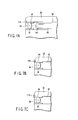
- FIGS. 7A to 7C A sixth embodiment will now be described with reference to FIGS. 7A to 7C.
- the embodiment is a modification of the first embodiment. Therefore, like numerals are used to designate like members of the first and sixth embodiments, and a detailed description of those members will be omitted in the following.
- a frame member 44 is melted by spot-irradiating a part of its distal end face with laser light.
- molten metal of the melted frame member 44 that is run out forward from a rigid portion 22 is set.
- a weld portion 114 is formed that combines the functions of the fixing portion 70 and the holding portion 72 according to the first embodiment.
- the weld portion 114 that doubles as the fixing portion 70 and the holding portion 72 can be formed by one cycle of laser irradiation. Accordingly, manufacturing processes can be simplified, so that cost can be reduced. While the position of irradiation must be settled before the laser light is applied, the positioning frequency can be reduced.
- the weld portion 114 has been described above as being formed with use of the melted frame member 44 as a base material. Alternatively, however, it may be formed in the manner shown in FIGS. 7B and 7C. In this case, notches for a solder deposit 116 are suitably formed in advance in a rigid portion body 32 and the frame member 44, as shown in FIG. 7B. The weld portion 118 is formed by applying laser light to the deposit 116 in the notches, as shown in FIG. 7C.
- a seventh embodiment will now be described with reference to FIGS. 8A to 9C.
- the embodiment is a modification of the first embodiment. Therefore, like numerals are used to designate like members of the first and seventh embodiments, and a detailed description of those members will be omitted in the following.
- FIG. 8A shows an illumination lens 52 having a chamfer portion 52a formed on a part of its distal-side outer peripheral edge.
- FIG. 8B shows a frame member 44 having a chamfer portion 44a formed on a part of its distal-side outer peripheral edge.
- the illumination lens 52 is bonded to a rigid portion body 32 with an adhesive.
- a punch hole 120 is formed in the peripheral edge portion of each of second and third circular holes 36 and 38 (or near the circular holes 36 and 38 for illumination lenses 52) of the body 32 in which the illumination lens 52 is fixed.
- a caulking tool 122 on the left-hand side of FIG. 9A is held and pressed against the punch hole 120. That part of the rigid portion body 32 which is held between the tool 122 and the chamfer portion 52a of the illumination lens 52 is plastically deformed to form a holding portion (worked portion) 124 shown in FIG. 9B.
- FIG. 9C shows a state in which an objective cover lens 46 and a first convex lens 56 that constitute an objective optical system are held to the rigid portion body 32 by the frame member 44.
- the body 32 is partially deformed to be provided with a holding portion 126 for retaining the chamfer portion 44a of the frame member 44.
- the holding portion 126 is formed by the same processes as those for the holding portion 124 described with reference to FIGS. 9A and 9B.
- a holding portion 128 is formed on the distal end portion of the frame member 44 so that the objective cover lens 46 with a chamfer portion 46a, like the illumination lens 52, can be held to the distal end portion of the frame member 44.
- the holding portion 128 is formed in the same manner as the constricted portion 90 (see FIG. 3) according to the second embodiment.
- the objective cover lens 46, illumination lenses 52, and other lens can be prevented from slipping off the rigid portion body 32 without using any large-sized working apparatus, such as a laser apparatus.
Landscapes
- Health & Medical Sciences (AREA)
- Life Sciences & Earth Sciences (AREA)
- Surgery (AREA)
- Engineering & Computer Science (AREA)
- Biomedical Technology (AREA)
- Molecular Biology (AREA)
- Pathology (AREA)
- Radiology & Medical Imaging (AREA)
- Nuclear Medicine, Radiotherapy & Molecular Imaging (AREA)
- Biophysics (AREA)
- Physics & Mathematics (AREA)
- Heart & Thoracic Surgery (AREA)
- Medical Informatics (AREA)
- Optics & Photonics (AREA)
- Animal Behavior & Ethology (AREA)
- General Health & Medical Sciences (AREA)
- Public Health (AREA)
- Veterinary Medicine (AREA)
- Manufacturing & Machinery (AREA)
- Endoscopes (AREA)
- Instruments For Viewing The Inside Of Hollow Bodies (AREA)
- Eye Examination Apparatus (AREA)
Applications Claiming Priority (2)
| Application Number | Priority Date | Filing Date | Title |
|---|---|---|---|
| JP2003356532 | 2003-10-16 | ||
| JP2003356532A JP3877718B2 (ja) | 2003-10-16 | 2003-10-16 | 内視鏡 |
Publications (2)
| Publication Number | Publication Date |
|---|---|
| EP1523933A1 true EP1523933A1 (fr) | 2005-04-20 |
| EP1523933B1 EP1523933B1 (fr) | 2008-02-20 |
Family
ID=34373598
Family Applications (1)
| Application Number | Title | Priority Date | Filing Date |
|---|---|---|---|
| EP04024384A Expired - Lifetime EP1523933B1 (fr) | 2003-10-16 | 2004-10-13 | Endoscope |
Country Status (5)
| Country | Link |
|---|---|
| US (1) | US7409130B2 (fr) |
| EP (1) | EP1523933B1 (fr) |
| JP (1) | JP3877718B2 (fr) |
| AT (1) | ATE386458T1 (fr) |
| DE (1) | DE602004011868T2 (fr) |
Cited By (2)
| Publication number | Priority date | Publication date | Assignee | Title |
|---|---|---|---|---|
| GB2469756A (en) * | 2009-04-25 | 2010-10-27 | Scholly Fiberoptic Gmbh | Optical viewing device and maintenance process for the device |
| EP1964505A4 (fr) * | 2005-12-19 | 2013-07-17 | Olympus Medical Systems Corp | Endoscope à capsule et procédé pour fabriquer celui-ci |
Families Citing this family (44)
| Publication number | Priority date | Publication date | Assignee | Title |
|---|---|---|---|---|
| JP5366575B2 (ja) * | 2008-05-08 | 2013-12-11 | Hoya株式会社 | 複数機種の内視鏡 |
| JP2009282071A (ja) * | 2008-05-19 | 2009-12-03 | Fujinon Corp | レンズ組立体および撮像装置 |
| US8926502B2 (en) | 2011-03-07 | 2015-01-06 | Endochoice, Inc. | Multi camera endoscope having a side service channel |
| US9402533B2 (en) | 2011-03-07 | 2016-08-02 | Endochoice Innovation Center Ltd. | Endoscope circuit board assembly |
| US11547275B2 (en) | 2009-06-18 | 2023-01-10 | Endochoice, Inc. | Compact multi-viewing element endoscope system |
| US9492063B2 (en) | 2009-06-18 | 2016-11-15 | Endochoice Innovation Center Ltd. | Multi-viewing element endoscope |
| US11278190B2 (en) | 2009-06-18 | 2022-03-22 | Endochoice, Inc. | Multi-viewing element endoscope |
| US9706903B2 (en) | 2009-06-18 | 2017-07-18 | Endochoice, Inc. | Multiple viewing elements endoscope system with modular imaging units |
| WO2012077116A1 (fr) | 2010-12-09 | 2012-06-14 | Peermedical Ltd. | Carte de circuit électronique flexible pour endoscope à caméras multiples |
| US9642513B2 (en) | 2009-06-18 | 2017-05-09 | Endochoice Inc. | Compact multi-viewing element endoscope system |
| US9713417B2 (en) | 2009-06-18 | 2017-07-25 | Endochoice, Inc. | Image capture assembly for use in a multi-viewing elements endoscope |
| US9101268B2 (en) | 2009-06-18 | 2015-08-11 | Endochoice Innovation Center Ltd. | Multi-camera endoscope |
| US9101287B2 (en) | 2011-03-07 | 2015-08-11 | Endochoice Innovation Center Ltd. | Multi camera endoscope assembly having multiple working channels |
| EP2442706B1 (fr) | 2009-06-18 | 2014-11-12 | EndoChoice Innovation Center Ltd. | Endoscope à caméras multiples |
| US12137873B2 (en) | 2009-06-18 | 2024-11-12 | Endochoice, Inc. | Compact multi-viewing element endoscope system |
| US11864734B2 (en) | 2009-06-18 | 2024-01-09 | Endochoice, Inc. | Multi-camera endoscope |
| US9901244B2 (en) | 2009-06-18 | 2018-02-27 | Endochoice, Inc. | Circuit board assembly of a multiple viewing elements endoscope |
| US9872609B2 (en) | 2009-06-18 | 2018-01-23 | Endochoice Innovation Center Ltd. | Multi-camera endoscope |
| US10165929B2 (en) | 2009-06-18 | 2019-01-01 | Endochoice, Inc. | Compact multi-viewing element endoscope system |
| KR101814830B1 (ko) * | 2009-09-16 | 2018-01-04 | 메디거스 엘티디. | 소구경 비디오 카메라 헤드 및 가시화 프로브와 이들을 포함하는 의료 디바이스 |
| US20140320621A1 (en) | 2009-09-16 | 2014-10-30 | Medigus Ltd. | Small diameter video camera heads and visualization probes and medical devices containing them |
| US12220105B2 (en) | 2010-06-16 | 2025-02-11 | Endochoice, Inc. | Circuit board assembly of a multiple viewing elements endoscope |
| US9560953B2 (en) | 2010-09-20 | 2017-02-07 | Endochoice, Inc. | Operational interface in a multi-viewing element endoscope |
| EP4233680B1 (fr) | 2010-09-20 | 2025-06-18 | EndoChoice, Inc. | Section distal d'endoscope comprenant un composant unique de canalisation de fluides |
| US12204087B2 (en) | 2010-10-28 | 2025-01-21 | Endochoice, Inc. | Optical systems for multi-sensor endoscopes |
| EP2635932B1 (fr) | 2010-10-28 | 2019-06-05 | EndoChoice Innovation Center Ltd. | Systèmes optiques pour endoscopes à capteurs multiples |
| US11889986B2 (en) | 2010-12-09 | 2024-02-06 | Endochoice, Inc. | Flexible electronic circuit board for a multi-camera endoscope |
| EP3420886B8 (fr) | 2010-12-09 | 2020-07-15 | EndoChoice, Inc. | Endoscope multicaméra à carte de circuit électronique souple |
| CN103491854B (zh) | 2011-02-07 | 2016-08-24 | 恩多卓斯创新中心有限公司 | 用于多摄影机内窥镜的多元件罩 |
| CA2798716A1 (fr) | 2011-12-13 | 2013-06-13 | Endochoice Innovation Center Ltd. | Endoscope a pointe amovible |
| CA2798729A1 (fr) | 2011-12-13 | 2013-06-13 | Peermedical Ltd. | Connecteur rotatif pour un endoscope |
| US9560954B2 (en) | 2012-07-24 | 2017-02-07 | Endochoice, Inc. | Connector for use with endoscope |
| US8659842B1 (en) * | 2012-09-13 | 2014-02-25 | Himax Technologies Limited | Image capturing device and assembling method thereof |
| US9986899B2 (en) | 2013-03-28 | 2018-06-05 | Endochoice, Inc. | Manifold for a multiple viewing elements endoscope |
| US9993142B2 (en) | 2013-03-28 | 2018-06-12 | Endochoice, Inc. | Fluid distribution device for a multiple viewing elements endoscope |
| US10499794B2 (en) | 2013-05-09 | 2019-12-10 | Endochoice, Inc. | Operational interface in a multi-viewing element endoscope |
| JP5767279B2 (ja) * | 2013-07-08 | 2015-08-19 | オリンパス株式会社 | レンズ組立体 |
| CN106455922B (zh) * | 2014-05-15 | 2018-03-27 | 奥林巴斯株式会社 | 光学单元和具有该光学单元的内窥镜 |
| KR20180114363A (ko) * | 2017-04-10 | 2018-10-18 | 서울바이오시스 주식회사 | 내시경 장치 및 이를 이용한 내시경 방법 |
| DE102018105846A1 (de) * | 2018-03-14 | 2019-09-19 | Olympus Winter & Ibe Gmbh | Optisches System für ein Endoskop und Verfahren zum Fixieren einer distalen optischen Baugruppe an einer proximalen optischen Baugruppe eines optischen Systems für ein Endoskop |
| WO2020031261A1 (fr) * | 2018-08-07 | 2020-02-13 | オリンパス株式会社 | Plaquette de lentilles, réseau de lentilles en couches et endoscope |
| WO2020039622A1 (fr) * | 2018-08-21 | 2020-02-27 | オリンパス株式会社 | Dispositif endoscopique |
| US11690497B2 (en) | 2018-11-27 | 2023-07-04 | Fujikura Ltd. | Lens unit |
| DE102020122846A1 (de) * | 2020-09-01 | 2022-03-03 | Karl Storz Se & Co. Kg | Optisches Instrument und Verfahren zum Herstellen eines optischen Instruments |
Citations (4)
| Publication number | Priority date | Publication date | Assignee | Title |
|---|---|---|---|---|
| EP0072205A1 (fr) * | 1981-08-05 | 1983-02-16 | Olympus Optical Co., Ltd. | Pièce d'assemblage pour le couvre-objet d'un endoscope |
| JPH09234183A (ja) * | 1995-12-25 | 1997-09-09 | Asahi Optical Co Ltd | 内視鏡の露出部品固定部 |
| EP0978251A1 (fr) * | 1998-08-07 | 2000-02-09 | Olympus Optical Co., Ltd. | Endoscope pouvant être passé à l'autoclave |
| US20020186478A1 (en) * | 2001-06-07 | 2002-12-12 | Fuji Photo Optical Co., Ltd. | Lens assembly for endoscopic lens system |
Family Cites Families (5)
| Publication number | Priority date | Publication date | Assignee | Title |
|---|---|---|---|---|
| JPS5731832A (en) | 1980-08-01 | 1982-02-20 | Olympus Optical Co | Cover glass attachment of endoscope |
| JPH05887A (ja) | 1991-06-21 | 1993-01-08 | Toshiba Corp | 分子線結晶成長装置 |
| US5621830A (en) * | 1995-06-07 | 1997-04-15 | Smith & Nephew Dyonics Inc. | Rotatable fiber optic joint |
| JP3637121B2 (ja) | 1995-12-21 | 2005-04-13 | ペンタックス株式会社 | 内視鏡のカバーレンズ固定部 |
| JP2002085326A (ja) | 2000-09-14 | 2002-03-26 | Olympus Optical Co Ltd | 内視鏡 |
-
2003
- 2003-10-16 JP JP2003356532A patent/JP3877718B2/ja not_active Expired - Fee Related
-
2004
- 2004-10-13 EP EP04024384A patent/EP1523933B1/fr not_active Expired - Lifetime
- 2004-10-13 DE DE602004011868T patent/DE602004011868T2/de not_active Expired - Lifetime
- 2004-10-13 AT AT04024384T patent/ATE386458T1/de not_active IP Right Cessation
- 2004-10-15 US US10/966,373 patent/US7409130B2/en not_active Expired - Lifetime
Patent Citations (4)
| Publication number | Priority date | Publication date | Assignee | Title |
|---|---|---|---|---|
| EP0072205A1 (fr) * | 1981-08-05 | 1983-02-16 | Olympus Optical Co., Ltd. | Pièce d'assemblage pour le couvre-objet d'un endoscope |
| JPH09234183A (ja) * | 1995-12-25 | 1997-09-09 | Asahi Optical Co Ltd | 内視鏡の露出部品固定部 |
| EP0978251A1 (fr) * | 1998-08-07 | 2000-02-09 | Olympus Optical Co., Ltd. | Endoscope pouvant être passé à l'autoclave |
| US20020186478A1 (en) * | 2001-06-07 | 2002-12-12 | Fuji Photo Optical Co., Ltd. | Lens assembly for endoscopic lens system |
Non-Patent Citations (1)
| Title |
|---|
| PATENT ABSTRACTS OF JAPAN vol. 1998, no. 01 30 January 1998 (1998-01-30) * |
Cited By (4)
| Publication number | Priority date | Publication date | Assignee | Title |
|---|---|---|---|---|
| EP1964505A4 (fr) * | 2005-12-19 | 2013-07-17 | Olympus Medical Systems Corp | Endoscope à capsule et procédé pour fabriquer celui-ci |
| GB2469756A (en) * | 2009-04-25 | 2010-10-27 | Scholly Fiberoptic Gmbh | Optical viewing device and maintenance process for the device |
| GB2469756B (en) * | 2009-04-25 | 2014-04-09 | Scholly Fiberoptic Gmbh | Optical viewing device and maintenance method for an optical viewing device |
| DE102009018960B4 (de) | 2009-04-25 | 2021-07-22 | Schölly Fiberoptic GmbH | Optisches Sichtgerät und Verfahren zur Wartung eines optischen Sichtgeräts |
Also Published As
| Publication number | Publication date |
|---|---|
| ATE386458T1 (de) | 2008-03-15 |
| DE602004011868T2 (de) | 2009-03-19 |
| JP3877718B2 (ja) | 2007-02-07 |
| US7409130B2 (en) | 2008-08-05 |
| JP2005118294A (ja) | 2005-05-12 |
| DE602004011868D1 (de) | 2008-04-03 |
| US20050089286A1 (en) | 2005-04-28 |
| EP1523933B1 (fr) | 2008-02-20 |
Similar Documents
| Publication | Publication Date | Title |
|---|---|---|
| EP1523933B1 (fr) | Endoscope | |
| US11116385B2 (en) | Endoscope cap | |
| US6717092B2 (en) | Method of manufacturing treatment instrument of endoscope | |
| JP4719225B2 (ja) | 内視鏡把持部及び内視鏡並びにその製造方法 | |
| US20190117045A1 (en) | Endoscope cap, endoscope and method of manufacturing endoscope cap | |
| JPH06133926A (ja) | 関節鏡探針の組立方法 | |
| JP3818693B2 (ja) | 内視鏡用湾曲管 | |
| JP2001258822A (ja) | 内視鏡 | |
| WO2011148894A1 (fr) | Endoscope | |
| EP1157655B1 (fr) | Capteur d'images pour un endoscope | |
| EP2695567A1 (fr) | Endoscope | |
| JP2005177025A (ja) | 内視鏡 | |
| JP2009279182A (ja) | 内視鏡 | |
| JP2005055811A (ja) | 光学部材、この光学部材を組み込む光学機器、及びその光学機器の組み立て方法 | |
| JP2002085326A (ja) | 内視鏡 | |
| JP3190642B2 (ja) | レーザプローブ | |
| JPH09127432A (ja) | 工業用内視鏡 | |
| JP2002336267A (ja) | レーザ光照射装置 | |
| JP3228618B2 (ja) | 内視鏡 | |
| JP2020054659A (ja) | 医療用ハンドピース | |
| AU2019383543B2 (en) | Torque wrench for connecting a replaceable instrument tip to a hand piece, system comprising a torque wrench and an instrument tip and method for connecting an instrument tip to a hand piece | |
| JP2001277177A (ja) | 作業支援装置 | |
| JPH02206420A (ja) | 内視鏡用アングル装置 | |
| JP3975011B2 (ja) | 内視鏡 | |
| JP2018120005A (ja) | 対物レンズユニット |
Legal Events
| Date | Code | Title | Description |
|---|---|---|---|
| PUAI | Public reference made under article 153(3) epc to a published international application that has entered the european phase |
Free format text: ORIGINAL CODE: 0009012 |
|
| 17P | Request for examination filed |
Effective date: 20041013 |
|
| AK | Designated contracting states |
Kind code of ref document: A1 Designated state(s): AT BE BG CH CY CZ DE DK EE ES FI FR GB GR HU IE IT LI LU MC NL PL PT RO SE SI SK TR |
|
| AX | Request for extension of the european patent |
Extension state: AL HR LT LV MK |
|
| AKX | Designation fees paid |
Designated state(s): AT BE BG CH CY CZ DE DK EE ES FI FR GB GR HU IE IT LI LU MC NL PL PT RO SE SI SK TR |
|
| GRAP | Despatch of communication of intention to grant a patent |
Free format text: ORIGINAL CODE: EPIDOSNIGR1 |
|
| GRAS | Grant fee paid |
Free format text: ORIGINAL CODE: EPIDOSNIGR3 |
|
| GRAA | (expected) grant |
Free format text: ORIGINAL CODE: 0009210 |
|
| AK | Designated contracting states |
Kind code of ref document: B1 Designated state(s): AT BE BG CH CY CZ DE DK EE ES FI FR GB GR HU IE IT LI LU MC NL PL PT RO SE SI SK TR |
|
| REG | Reference to a national code |
Ref country code: GB Ref legal event code: FG4D |
|
| REG | Reference to a national code |
Ref country code: CH Ref legal event code: EP |
|
| REG | Reference to a national code |
Ref country code: IE Ref legal event code: FG4D |
|
| REF | Corresponds to: |
Ref document number: 602004011868 Country of ref document: DE Date of ref document: 20080403 Kind code of ref document: P |
|
| REG | Reference to a national code |
Ref country code: CH Ref legal event code: NV Representative=s name: E. BLUM & CO. AG PATENT- UND MARKENANWAELTE VSP |
|
| PG25 | Lapsed in a contracting state [announced via postgrant information from national office to epo] |
Ref country code: FI Free format text: LAPSE BECAUSE OF FAILURE TO SUBMIT A TRANSLATION OF THE DESCRIPTION OR TO PAY THE FEE WITHIN THE PRESCRIBED TIME-LIMIT Effective date: 20080220 Ref country code: ES Free format text: LAPSE BECAUSE OF FAILURE TO SUBMIT A TRANSLATION OF THE DESCRIPTION OR TO PAY THE FEE WITHIN THE PRESCRIBED TIME-LIMIT Effective date: 20080531 |
|
| NLV1 | Nl: lapsed or annulled due to failure to fulfill the requirements of art. 29p and 29m of the patents act | ||
| ET | Fr: translation filed | ||
| PG25 | Lapsed in a contracting state [announced via postgrant information from national office to epo] |
Ref country code: PL Free format text: LAPSE BECAUSE OF FAILURE TO SUBMIT A TRANSLATION OF THE DESCRIPTION OR TO PAY THE FEE WITHIN THE PRESCRIBED TIME-LIMIT Effective date: 20080220 Ref country code: SI Free format text: LAPSE BECAUSE OF FAILURE TO SUBMIT A TRANSLATION OF THE DESCRIPTION OR TO PAY THE FEE WITHIN THE PRESCRIBED TIME-LIMIT Effective date: 20080220 |
|
| PG25 | Lapsed in a contracting state [announced via postgrant information from national office to epo] |
Ref country code: SK Free format text: LAPSE BECAUSE OF FAILURE TO SUBMIT A TRANSLATION OF THE DESCRIPTION OR TO PAY THE FEE WITHIN THE PRESCRIBED TIME-LIMIT Effective date: 20080220 Ref country code: PT Free format text: LAPSE BECAUSE OF FAILURE TO SUBMIT A TRANSLATION OF THE DESCRIPTION OR TO PAY THE FEE WITHIN THE PRESCRIBED TIME-LIMIT Effective date: 20080721 Ref country code: SE Free format text: LAPSE BECAUSE OF FAILURE TO SUBMIT A TRANSLATION OF THE DESCRIPTION OR TO PAY THE FEE WITHIN THE PRESCRIBED TIME-LIMIT Effective date: 20080520 Ref country code: CZ Free format text: LAPSE BECAUSE OF FAILURE TO SUBMIT A TRANSLATION OF THE DESCRIPTION OR TO PAY THE FEE WITHIN THE PRESCRIBED TIME-LIMIT Effective date: 20080220 Ref country code: DK Free format text: LAPSE BECAUSE OF FAILURE TO SUBMIT A TRANSLATION OF THE DESCRIPTION OR TO PAY THE FEE WITHIN THE PRESCRIBED TIME-LIMIT Effective date: 20080220 Ref country code: NL Free format text: LAPSE BECAUSE OF FAILURE TO SUBMIT A TRANSLATION OF THE DESCRIPTION OR TO PAY THE FEE WITHIN THE PRESCRIBED TIME-LIMIT Effective date: 20080220 |
|
| PG25 | Lapsed in a contracting state [announced via postgrant information from national office to epo] |
Ref country code: RO Free format text: LAPSE BECAUSE OF FAILURE TO SUBMIT A TRANSLATION OF THE DESCRIPTION OR TO PAY THE FEE WITHIN THE PRESCRIBED TIME-LIMIT Effective date: 20080220 |
|
| PLBE | No opposition filed within time limit |
Free format text: ORIGINAL CODE: 0009261 |
|
| STAA | Information on the status of an ep patent application or granted ep patent |
Free format text: STATUS: NO OPPOSITION FILED WITHIN TIME LIMIT |
|
| 26N | No opposition filed |
Effective date: 20081121 |
|
| PGFP | Annual fee paid to national office [announced via postgrant information from national office to epo] |
Ref country code: CH Payment date: 20081016 Year of fee payment: 5 Ref country code: LU Payment date: 20081016 Year of fee payment: 5 Ref country code: MC Payment date: 20081020 Year of fee payment: 5 |
|
| PGFP | Annual fee paid to national office [announced via postgrant information from national office to epo] |
Ref country code: AT Payment date: 20081013 Year of fee payment: 5 |
|
| PGFP | Annual fee paid to national office [announced via postgrant information from national office to epo] |
Ref country code: BE Payment date: 20081010 Year of fee payment: 5 |
|
| PG25 | Lapsed in a contracting state [announced via postgrant information from national office to epo] |
Ref country code: EE Free format text: LAPSE BECAUSE OF FAILURE TO SUBMIT A TRANSLATION OF THE DESCRIPTION OR TO PAY THE FEE WITHIN THE PRESCRIBED TIME-LIMIT Effective date: 20080220 Ref country code: BG Free format text: LAPSE BECAUSE OF FAILURE TO SUBMIT A TRANSLATION OF THE DESCRIPTION OR TO PAY THE FEE WITHIN THE PRESCRIBED TIME-LIMIT Effective date: 20080520 |
|
| PG25 | Lapsed in a contracting state [announced via postgrant information from national office to epo] |
Ref country code: CY Free format text: LAPSE BECAUSE OF FAILURE TO SUBMIT A TRANSLATION OF THE DESCRIPTION OR TO PAY THE FEE WITHIN THE PRESCRIBED TIME-LIMIT Effective date: 20080220 |
|
| PG25 | Lapsed in a contracting state [announced via postgrant information from national office to epo] |
Ref country code: IT Free format text: LAPSE BECAUSE OF FAILURE TO SUBMIT A TRANSLATION OF THE DESCRIPTION OR TO PAY THE FEE WITHIN THE PRESCRIBED TIME-LIMIT Effective date: 20080220 |
|
| BERE | Be: lapsed |
Owner name: OLYMPUS CORP. Effective date: 20091031 |
|
| PG25 | Lapsed in a contracting state [announced via postgrant information from national office to epo] |
Ref country code: MC Free format text: LAPSE BECAUSE OF NON-PAYMENT OF DUE FEES Effective date: 20091031 |
|
| REG | Reference to a national code |
Ref country code: CH Ref legal event code: PL |
|
| PG25 | Lapsed in a contracting state [announced via postgrant information from national office to epo] |
Ref country code: HU Free format text: LAPSE BECAUSE OF FAILURE TO SUBMIT A TRANSLATION OF THE DESCRIPTION OR TO PAY THE FEE WITHIN THE PRESCRIBED TIME-LIMIT Effective date: 20080821 |
|
| PG25 | Lapsed in a contracting state [announced via postgrant information from national office to epo] |
Ref country code: AT Free format text: LAPSE BECAUSE OF NON-PAYMENT OF DUE FEES Effective date: 20091013 Ref country code: TR Free format text: LAPSE BECAUSE OF FAILURE TO SUBMIT A TRANSLATION OF THE DESCRIPTION OR TO PAY THE FEE WITHIN THE PRESCRIBED TIME-LIMIT Effective date: 20080220 |
|
| PG25 | Lapsed in a contracting state [announced via postgrant information from national office to epo] |
Ref country code: BE Free format text: LAPSE BECAUSE OF NON-PAYMENT OF DUE FEES Effective date: 20091031 Ref country code: CH Free format text: LAPSE BECAUSE OF NON-PAYMENT OF DUE FEES Effective date: 20091031 Ref country code: LI Free format text: LAPSE BECAUSE OF NON-PAYMENT OF DUE FEES Effective date: 20091031 Ref country code: GR Free format text: LAPSE BECAUSE OF FAILURE TO SUBMIT A TRANSLATION OF THE DESCRIPTION OR TO PAY THE FEE WITHIN THE PRESCRIBED TIME-LIMIT Effective date: 20080521 |
|
| PG25 | Lapsed in a contracting state [announced via postgrant information from national office to epo] |
Ref country code: LU Free format text: LAPSE BECAUSE OF NON-PAYMENT OF DUE FEES Effective date: 20091013 |
|
| PGFP | Annual fee paid to national office [announced via postgrant information from national office to epo] |
Ref country code: IE Payment date: 20141009 Year of fee payment: 11 Ref country code: FR Payment date: 20141008 Year of fee payment: 11 Ref country code: GB Payment date: 20141008 Year of fee payment: 11 |
|
| GBPC | Gb: european patent ceased through non-payment of renewal fee |
Effective date: 20151013 |
|
| REG | Reference to a national code |
Ref country code: IE Ref legal event code: MM4A |
|
| PG25 | Lapsed in a contracting state [announced via postgrant information from national office to epo] |
Ref country code: GB Free format text: LAPSE BECAUSE OF NON-PAYMENT OF DUE FEES Effective date: 20151013 |
|
| REG | Reference to a national code |
Ref country code: FR Ref legal event code: ST Effective date: 20160630 |
|
| PG25 | Lapsed in a contracting state [announced via postgrant information from national office to epo] |
Ref country code: FR Free format text: LAPSE BECAUSE OF NON-PAYMENT OF DUE FEES Effective date: 20151102 |
|
| PG25 | Lapsed in a contracting state [announced via postgrant information from national office to epo] |
Ref country code: IE Free format text: LAPSE BECAUSE OF NON-PAYMENT OF DUE FEES Effective date: 20151013 |
|
| PGFP | Annual fee paid to national office [announced via postgrant information from national office to epo] |
Ref country code: DE Payment date: 20211020 Year of fee payment: 18 |
|
| REG | Reference to a national code |
Ref country code: DE Ref legal event code: R119 Ref document number: 602004011868 Country of ref document: DE |
|
| PG25 | Lapsed in a contracting state [announced via postgrant information from national office to epo] |
Ref country code: DE Free format text: LAPSE BECAUSE OF NON-PAYMENT OF DUE FEES Effective date: 20230503 |