EP1523934B1 - Agencement de capteur - Google Patents
Agencement de capteur Download PDFInfo
- Publication number
- EP1523934B1 EP1523934B1 EP04104961A EP04104961A EP1523934B1 EP 1523934 B1 EP1523934 B1 EP 1523934B1 EP 04104961 A EP04104961 A EP 04104961A EP 04104961 A EP04104961 A EP 04104961A EP 1523934 B1 EP1523934 B1 EP 1523934B1
- Authority
- EP
- European Patent Office
- Prior art keywords
- electrode
- electrodes
- sensor
- arrangement
- patient
- Prior art date
- Legal status (The legal status is an assumption and is not a legal conclusion. Google has not performed a legal analysis and makes no representation as to the accuracy of the status listed.)
- Expired - Lifetime
Links
Images





Classifications
-
- A—HUMAN NECESSITIES
- A61—MEDICAL OR VETERINARY SCIENCE; HYGIENE
- A61B—DIAGNOSIS; SURGERY; IDENTIFICATION
- A61B5/00—Measuring for diagnostic purposes; Identification of persons
- A61B5/68—Arrangements of detecting, measuring or recording means, e.g. sensors, in relation to patient
- A61B5/6801—Arrangements of detecting, measuring or recording means, e.g. sensors, in relation to patient specially adapted to be attached to or worn on the body surface
- A61B5/684—Indicating the position of the sensor on the body
- A61B5/6841—Indicating the position of the sensor on the body by using templates
-
- A—HUMAN NECESSITIES
- A61—MEDICAL OR VETERINARY SCIENCE; HYGIENE
- A61B—DIAGNOSIS; SURGERY; IDENTIFICATION
- A61B5/00—Measuring for diagnostic purposes; Identification of persons
- A61B5/103—Measuring devices for testing the shape, pattern, colour, size or movement of the body or parts thereof, for diagnostic purposes
- A61B5/11—Measuring movement of the entire body or parts thereof, e.g. head or hand tremor or mobility of a limb
- A61B5/1104—Measuring movement of the entire body or parts thereof, e.g. head or hand tremor or mobility of a limb induced by stimuli or drugs
- A61B5/1106—Measuring movement of the entire body or parts thereof, e.g. head or hand tremor or mobility of a limb induced by stimuli or drugs to assess neuromuscular blockade, e.g. to estimate depth of anaesthesia
-
- A—HUMAN NECESSITIES
- A61—MEDICAL OR VETERINARY SCIENCE; HYGIENE
- A61B—DIAGNOSIS; SURGERY; IDENTIFICATION
- A61B5/00—Measuring for diagnostic purposes; Identification of persons
- A61B5/24—Detecting, measuring or recording bioelectric or biomagnetic signals of the body or parts thereof
- A61B5/316—Modalities, i.e. specific diagnostic methods
- A61B5/388—Nerve conduction study, e.g. detecting action potential of peripheral nerves
-
- A—HUMAN NECESSITIES
- A61—MEDICAL OR VETERINARY SCIENCE; HYGIENE
- A61B—DIAGNOSIS; SURGERY; IDENTIFICATION
- A61B5/00—Measuring for diagnostic purposes; Identification of persons
- A61B5/24—Detecting, measuring or recording bioelectric or biomagnetic signals of the body or parts thereof
- A61B5/316—Modalities, i.e. specific diagnostic methods
- A61B5/389—Electromyography [EMG]
- A61B5/395—Details of stimulation, e.g. nerve stimulation to elicit EMG response
-
- A—HUMAN NECESSITIES
- A61—MEDICAL OR VETERINARY SCIENCE; HYGIENE
- A61B—DIAGNOSIS; SURGERY; IDENTIFICATION
- A61B5/00—Measuring for diagnostic purposes; Identification of persons
- A61B5/48—Other medical applications
- A61B5/4821—Determining level or depth of anaesthesia
-
- A—HUMAN NECESSITIES
- A61—MEDICAL OR VETERINARY SCIENCE; HYGIENE
- A61B—DIAGNOSIS; SURGERY; IDENTIFICATION
- A61B5/00—Measuring for diagnostic purposes; Identification of persons
- A61B5/0059—Measuring for diagnostic purposes; Identification of persons using light, e.g. diagnosis by transillumination, diascopy, fluorescence
-
- A—HUMAN NECESSITIES
- A61—MEDICAL OR VETERINARY SCIENCE; HYGIENE
- A61B—DIAGNOSIS; SURGERY; IDENTIFICATION
- A61B5/00—Measuring for diagnostic purposes; Identification of persons
- A61B5/68—Arrangements of detecting, measuring or recording means, e.g. sensors, in relation to patient
- A61B5/6801—Arrangements of detecting, measuring or recording means, e.g. sensors, in relation to patient specially adapted to be attached to or worn on the body surface
- A61B5/6813—Specially adapted to be attached to a specific body part
- A61B5/6814—Head
Definitions
- the present invention relates to measuring anesthesia parameters from the head of a patient.
- Entropy which is derived from EEG and FEMG signals
- NMT and SpO2 are parameters widely used in anesthesia.
- Entropy parameter is the only parameter, which is exclusively measured from the head of the patient.
- SpO2 is sometimes measured from the ear if extremities cannot be used. So far NMT is mainly monitored from the hand. The parameters mentioned above can be described shortly as follows.
- SpO2 or pulse oximetry measures the oxygenation of the blood noninvasively. Blood absorbs red and infrared light differently depending on the oxygenation, ie. the colour of the blood varies with its oxygenation. By emitting red and infrared light through tissue and measuring the absorption of the two different wavelengths (red, about 660 nm and infrared, about 940 nm) the blood oxygenation can be calculated. There are two ways of doing this, transmission oximetry or reflectance oximetry. In transmission oximetry the emitter (two LEDs) and receiver (photodetector) are placed facing each other typically on each side of a finger, toe or earlobe. In reflectance oximetry the light is reflected below the tissue (eg.
- Neuro Muscular Transmission is the transfer of an impulse between a nerve and a muscle in the neuromuscular junction. NMT can be blocked by neuromuscular blocking agents-drugs, which cause transient muscle paralysis and prevent the patient from moving and breathing spontaneously. Muscle relaxation is used during general anesthesia to enable endotracheal intubation and to provide the surgeon with optimal working conditions.
- the level of neuromuscular block is routinely measured by stimulating a peripheral nerve, usually in the hand, and by evaluating the muscle response. The muscle response can be measured either visually, by touching the hand, using a mechanical piezoelectric sensor or measuring the EMG response (ie. electrical muscle activity).
- Neuromuscular transmission can also be measured from the face of the patient by stimulating the facial nerve and observing the response of the facial muscles.
- the entropy parameter is used to determine the level of hypnosis of an anesthesized patient.
- the Entropy parameter is based on EEG and EMG signals measured from the forehead of the patient.
- the EEG signal represents brain activity whereas EMG represents muscle activity. Entropy could be described as the level of irregularity in the EEG and EMG signals. When the patient is awake, there is more brain and muscle activity whereas an anesthesized patient has less brain and muscle activity.
- a considerable problem in the operating rooms is the large amount of cables and hoses extending from the patient to a patient monitor and other devices connected to the patient.
- the amount of cables and hoses is due to the fact that traditionally separate sensors have been connected for example to a patient monitor using a cable of its own or a hose of its own. This principle leads to a considerable amount of cables and hoses, which may cause difficulties in the operating rooms particularly in extreme situations.
- the object of the invention is to provide a sensor arrangement by which the problems of the prior art technique can be eliminated. This is obtained by the invention.
- the basic idea of the invention is described in claim 1.
- the sensor described herein provides a combination of the basic adequacy of anesthesia parameters into one compact sensor.
- the sensor gives a significant improvement to the current level of ergonomics and usability.
- the user only has to attach one sensor instead of three separate sensors, Entropy, NMT and SpO2.
- all parameters are measured from the same area, the face of the patient.
- the user also only needs to connect one cable to the sensor since all parameters are connected through one connector.
- the present invention eliminates or at lest drastically reduces said problem by combining several parameters into one cable and thereby reducing the "cable clutter".
- Entropy parameter is the only parameter, which is exclusively measured from the head of the patient. SpO2 is sometimes measured from the ear if extremities cannot be used. So far NMT is mainly monitored from hand, but in fact the face offers a good alternative location for NMT measurement. Since Entropy can also be measured from the forehead of the patient, the head is a logical location for the combined sensor. The Entropy electrodes are located on the forehead and temple area.
- Electrodes are also used for NMT stimulus and can also be used for NMT measurement (muscle response is measured by measuring the EMG response). To reduce the number of electrodes needed, some of the Entropy and NMT electrodes can be shared between the two parameters. The measurements can then be multiplexed to stimulate and measure potentials for the two different parameters. NMT can be measured either using a mechanical sensor sensing physical muscle movement or using electrodes measuring muscle activity electrically (EMG). Using a mechanical sensor requires a separate piezo-electric sensor over the muscle where the response is to be measured.
- EMG muscle activity electrically
- SpO2 is typically measured from the extremities or from the ear. It is, however, possible to measure SpO2 anywhere on the body where you can place an optical emitter and detector in such a fashion that the emitted light passes through oxygenated tissue. On the head of the patient such areas are the ears and the nose, and if the light is reflected off the scull, the forehead can be used as well.
- All parameters in the combined adequacy of anesthesia sensor can be reliably recorded from the head of the patient enabling a compact sensor. It is also possible to evaluate the amount of pain experienced by the patient (analgesia) by monitoring the heartrate and the amplitude of the plethysmographic curve (signal obtained from the SpO2 sensor). The analgesia parameter could also be derived from the SpO2 signal without additional sensors.
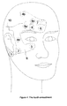
- the first embodiment of the invention is described in Figure 1 .
- the sensor arrangement shown in Figure 1 comprises an array of electrodes for measuring EEG, EMG and NMT.
- the electrodes are located on the face of the patient.
- Electrode 1 is located just posterior to the lower part of the pinna and electrode 2 is located just anterior to the tragus.
- Electrode 3 is located below the eye.
- Electrodes 4 and 5 have two alternative locations, a and b. If location b is used, electrode 4a is also used.
- Electrode 4a is located on the temple area between the corner of the eye and the hairline.
- Electrode 5a is located above the eye at the same level as electrode 6, which is located between the eyebrows of the patient at the center of the forehead, approximately 4 cm above the nose.
- Electrode 4b is located at either location F3 or F4 (left or right side) of the International 10-20 system.
- the International 10-20 system is described in "Monitoring in Anesthesia and Critical Care Medicine", Casey D. Blitt, Churchill Livingstone, 1985.
- Electrode 5b is located between electrode 4b and electrode 6.
- a reflective optical sensor 7 for monitoring substances in tissues e.g. SpO2 is placed on the face of the patient, anywhere where suitable for the structure of the sensor, eg. but not limited to on the forehead above electrode 6.
- the optical sensor 7 comprises an emitter and a receiver located close to each other. The emitter comprises LEDs of different wavelengths and the receiver comprises a photodetector.
- Electrodes 1 and 2 are the NMT stimulus electrodes, stimulating the facial nerve. Electrodes 4a and 6 are the NMT recording electrodes and electrode 5 (a or b) is the NMT grounding electrode. Electrodes 4 (a or b) and 6 also record EEG and EMG signals used e.g. to derive the Entropy parameter. Electrode 5 (a or b) is the reference electrode for the EEG and EMG measurement. The EEG and EMG measurement can be enhanced using electrode 3 e.g. but not limited to record eye movements. The EEG and EMG measurement can be done with or without electrode 3. The optical sensor measures e.g. the plethysmographic curve, the heartrate and the blood oxygen saturation.
- the embodiment shown in Figure 1 comprises also a base element 9.
- the base element 9 can be made of any appropriate flexible material, for example of plastic material.
- the electrodes and sensors described above can be attached to the base element by using any appropriate method known per se.
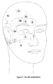
- the second embodiment is described in Figure 2 .
- the sensor arrangement shown in Figure 2 comprises an array of electrodes for measuring EEG, EMG and NMT.
- the electrodes are located on the face of the patient.
- Electrode 1 is located just posterior to the lower part of the pinna and electrode 2 is located just anterior to the tragus.
- Electrode 3 is located below the eye.
- Electrodes 4 and 5 have two alternative locations, a and b. If location b is used, electrode 4a is also used.
- Electrode 4a is located on the temple area between the corner of the eye and the hairline.
- Electrode 5a is located above the eye at the same level as electrode 6, which is located between the eyebrows of the patient at the center of the forehead, approximately 4 cm above the nose.
- Electrode 4b is located at either location F3 or F4 (left or right side) of the International 10-20 system. Electrode 5b is located between electrode 4b and electrode 6.
- a transmission optical sensor 7 for monitoring substances in tissues e.g. SpO2 is placed on the nose of the patient.
- the optical sensor 7 comprises an emitter and a receiver located on opposite sides of the nose.
- the emitter comprises LEDs of different wavelengths and the receiver comprises of a photodetector.
- Electrodes 1 and 2 are the NMT stimulus electrodes, stimulating the facial nerve. Electrodes 4a and 6 are the NMT recording electrodes and electrode 5 (a or b) is the NMT grounding electrode. Electrodes 4 (a or b) and 6 also record EEG and EMG signals used e.g. to derive the Entropy parameter. Electrode 5 (a or b) is the reference electrode for the EEG and EMG measurement. The EEG and EMG measurement can be enhanced using electrode 3 e.g. but not limited to record eye movements. The EEG and EMG measurement can be done with or without electrode 3. The optical sensor measures e.g. plethysmographic curve, the heartrate and the blood oxygen saturation.
- the embodiment shown in Figure 2 comprises also a base element 9.
- the base element 9 can be made of any appropriate flexible material, for example of plastic material.
- the electrodes and sensors described above can be attached to the base element by using any appropriate method known per se.
- All electrodes and sensors described above are connected to a single connector 10 attached to the base element 9 as shown in Figure 2 .
- a single connector 10 a series of connectors may be used as told before.
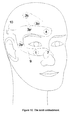
- the third embodiment is described in Figure 3 .
- the sensor arrangement shown in Figure 3 comprises an array of electrodes for measuring EEG, EMG and NMT.
- the electrodes are located on the face of the patient.
- Electrode 1 is located just posterior to the lower part of the pinna and electrode 2 is located just anterior to the tragus.
- Electrode 3 is located below the eye.
- Electrodes 4 and 5 have two alternative locations, a and b. If location b is used, electrode 4a is also used.
- Electrode 4a is located on the temple area between the corner of the eye and the hairline.
- Electrode 5a is located above the eye at the same level as electrode 6, which is located between the eyebrows of the patient at the center of the forehead, approximately 4 cm above the nose.
- Electrode 4b is located at either location F3 or F4 (left or right side) of the International 10-20 system. Electrode 5b is located between electrode 4b and electrode 6.
- a transmission optical sensor 7 for monitoring substances in tissues e.g. SpO2 is placed on the ear of the patient.
- the optical sensor 7 comprises an emitter and a receiver located on opposite sides of the auricle.
- the emitter comprises LEDs of different wavelengths and the receiver comprises a photodetector.
- Electrodes 1 and 2 are the NMT stimulus electrodes, stimulating the facial nerve. Electrodes 4a and 6 are the NMT recording electrodes and electrode 5 (a or b) is the NMT grounding electrode. Electrodes 4 (a or b) and 6 also record EEG and EMG signals used e.g. to derive the Entropy parameter. Electrode 5 (a or b) is the reference electrode for the EEG and EMG measurement. The EEG and EMG measurement can be enhanced using electrode 3 e.g. but not limited to record eye movements. The EEG and EMG measurement can be done with or without electrode 3. The optical sensor measures e.g. the plethysmographic curve, the heartrate and the blood oxygen saturation.
- the embodiment shown in Figure 3 comprises also a base element 9.
- the base element 9 can be made of any appropriate flexible material, for example of plastic material.
- the base element 9 can be formed and designed freely according to the existing need as shown in the Figures, ie. for example the base element 9 in Figure 3 is slightly different when compared to the base element 9 in Figure 1 .
- the electrodes and sensors described above can be attached to the base element by using any appropriate method known per se.
- the fourth embodiment is described in Figure 4 .
- the sensor arrangement shown in Figure 4 comprises an array of electrodes for measuring EEG, EMG and for NMT stimulus.
- the electrodes are located on the face of the patient.
- Electrode 1 is located just posterior to the lower part of the pinna and electrode 2 is located just anterior to the tragus.
- Electrode 3 is located below the eye.
- Electrodes 4 and 5 have two alternative locations, a and b.
- Electrode 4a is located on the temple area between the corner of the eye and the hairline.
- Electrode 5a is located above the eye at the same level as electrode 6, which is located between the eyebrows of the patient at the center of the forehead, approximately 4 cm above the nose.
- Electrode 4b is located at either location F3 or F4 (left or right side) of the International 10-20 system.
- Electrode 5b is located between electrode 4b and electrode 6.
- a reflective optical sensor 7 for monitoring substances in tissues e.g. SpO2 is placed on the face of the patient, anywhere where suitable for the structure of the sensor, eg. but not limited to on the forehead above electrode 6.
- the optical sensor 7 comprises an emitter and a receiver located close to each other.
- the emitter comprises LEDs of different wavelengths and the receiver comprises a photodetector.
- a mechanical piezoelectric sensor 8 is located over either the procerus, frontalis, corrugator or orbicularismuscle or a combination of these.
- Electrodes 1 and 2 are the NMT stimulus electrodes, stimulating the facial nerve. Electrodes 4 (a or b) and 6 record EEG and EMG signals used e.g. to derive the Entropy parameter. Electrode 5 (a or b) is the reference electrode for the EEG and EMG measurement. The EEG and EMG measurement can be enhanced using electrode 3 e.g. but not limited to record eye movements. The EEG and EMG measurement can be done with or without electrode 3.
- the optical sensor measures e.g. the plethysmographic curve, the heartrate and the blood oxygen saturation.
- the mechanical piezoelectric sensor 8 records muscle response to NMT stimulus.
- the embodiment shown in Figure 4 comprises according to the invention a base element 9.
- the base element 9 can be made of any appropriate flexible material, for example of plastic material.
- the electrodes and sensors described above can be attached to the base element by using any appropriate method known per se. As told before the form and the structure of the base element can be designed quite freely according to the existing need.
- the fifth embodiment is described in Figure 5 .
- the sensor arrangement shown in Figure 5 comprises an array of electrodes for measuring EEG, EMG and for NMT stimulus.
- the electrodes are located on the face of the patient.
- Electrode 1 is located just posterior to the lower part of the pinna and electrode 2 is located just anterior to the tragus.
- Electrode 3 is located below the eye.
- Electrodes 4 and 5 have two alternative locations, a and b.
- Electrode 4a is located on the temple area between the corner of the eye and the hairline.
- Electrode 5a is located above the eye at the same level as electrode 6, which is located between the eyebrows of the patient at the center of the forehead, approximately 4 cm above the nose.
- Electrode 4b is located at either location F3 or F4 (left or right side) of the International 10-20 system.
- Electrode 5b is located between electrode 4b and electrode 6.
- a transmission optical sensor 7 for monitoring substances in tissues e.g. SpO2 is placed on the nose of the patient.
- the optical sensor 7 comprises an emitter and a receiver located on opposite sides of the nose.
- the emitter comprises LEDs of different wavelengths and the receiver comprises a photodetector.
- a mechanical piezoelectric sensor 8 is located over either the procerus, frontalis, corrugator or orbicularis muscle or a combination of these.
- Electrodes 1 and 2 are the NMT stimulus electrodes, stimulating the facial nerve. Electrodes 4 (a or b) and 6 record EEG and EMG signals used e.g. to derive the Entropy parameter. Electrode 5 (a or b) is the reference electrode for the EEG and EMG measurement. The EEG and EMG measurement can be enhanced using electrode 3 e.g. but not limited to record eye movements. The EEG and EMG measurement can be done with or without electrode 3.
- the optical sensor measures e.g. the plethysmographic curve, the heartrate and the blood oxygen saturation.
- the mechanical piezoelectric sensor 8 records muscle response to NMT stimulus.
- the embodiment shown in Figure 5 comprises according to the invention a base element 9.
- the base element 9 can be made of any appropriate flexible material, for example of plastic material.
- the electrodes and sensors described above can be attached to the base element by using any appropriate method known per se. As told before the form and the structure of the base element can be designed quite freely according to the existing need.
- the sixth embodiment is described in Figure 6 .
- the sensor arrangement shown in Figure 6 comprises an array of electrodes for measuring EEG, EMG and for NMT stimulus.
- the electrodes are located on the face of the patient.
- Electrode 1 is located just posterior to the lower part of the pinna and electrode 2 is located just anterior to the tragus.
- Electrode 3 is located below the eye.
- Electrodes 4 and 5 have two alternative locations, a and b.
- Electrode 4a is located on the temple area between the corner of the eye and the hairline.
- Electrode 5a is located above the eye at the same level as electrode 6, which is located between the eyebrows of the patient at the center of the forehead, approximately 4 cm above the nose.
- Electrode 4b is located at either location F3 or F4 (left or right side) of the International 10-20 system.
- Electrode 5b is located between electrode 4b and electrode 6.
- a transmission optical sensor 7 for monitoring substances in tissues e.g. SpO2 is placed on the ear of the patient.
- the optical sensor 7 comprises an emitter and a receiver located on opposite sides of either auricle.
- the emitter comprises LEDs of different wavelengths and the receiver comprises a photodetector.
- a mechanical piezoelectric sensor 8 is located over either the procerus, frontalis, corrugator or orbicularis muscle or a combination of these.
- Electrodes 1 and 2 are the NMT stimulus electrodes, stimulating the facial nerve. Electrodes 4 (a or b) and 6 record EEG and EMG signals used e.g. to derive the Entropy parameter. Electrode 5 (a or b) is the reference electrode for the EEG and EMG measurement. The EEG and EMG measurement can be enhanced using electrode 3 e.g. but not limited to record eye movements. The EEG and EMG measurement can be done with or without electrode 3.
- the optical sensor measures e.g. the plethysmographic curve, the heartrate and the blood oxygen saturation.
- the mechanical piezoelectric sensor 8 records muscle response to NMT stimulus.
- the embodiment shown in Figure 6 comprises according to the invention a base element 9.
- the base element 9 can be made of any appropriate flexible material, for example of plastic material.
- the electrodes and sensors described above can be attached to the base element by using any appropriate method known per se. As told before the form and the structure of the base element can be designed quite freely according to the existing need.
- the seventh embodiment is described in Figure 7 .
- the sensor arrangement shown in Figure 7 comprises an array of electrodes for measuring EEG, EMG and NMT.
- the electrodes are located on the face of the patient.
- Electrode 1 is located just posterior to the lower part of the pinna and electrode 2 is located just anterior to the tragus.
- Electrode 3 is located below the eye.
- Electrodes 4 and 5 have two alternative locations, a and b. If location b is used, electrode 4a is also used.
- Electrode 4a is located on the temple area between the corner of the eye and the hairline.
- Electrode 5a is located above the eye at the same level as electrode 6, which is located between the eyebrows of the patient at the center of the forehead, approximately 4 cm above the nose.
- Electrode 4b is located at either location F3 or F4 (left or right side) of the International 10-20 system. Electrode 5b is located between electrode 4b and electrode 6.
- electrode 5b it is very advantageous to place electrode 5b essentially in the middle of electrodes 4b and 6 so that the distances between electrode 5b and electrode 4b, and electrode 5b and electrode 6 are essentially the same.
- Electrodes 1 and 2 are the NMT stimulus electrodes, stimulating the facial nerve. Electrodes 4a and 6 are the NMT recording electrodes and electrode 5 (a or b) is the NMT grounding electrode. Electrodes 4 (a or b) and 6 also record EEG and EMG signals used e.g. to derive the Entropy parameter. Electrode 5 (a or b) is the reference electrode for the EEG and EMG measurement. The EEG and EMG measurement can be enhanced using electrode 3 e.g. but not limited to record eye movements. The EEG and EMG measurement can be done with or without electrode 3.
- the embodiment shown in Figure 7 comprises according to the invention a base element 9.
- the base element 9 can be made of any appropriate flexible material, for example of plastic material.
- the electrodes and sensors described above can be attached to the base element by using any appropriate method known per se. As told before the form and the structure of the base element can be designed quite freely according to the existing need.
- the eighth embodiment is described in Figure 8 .
- the sensor arrangement shown in Figure 8 comprises an array of electrodes for measuring EEG, EMG and for NMT stimulus.
- the electrodes are located on the face of the patient.
- Electrode 1 is located just posterior to the lower part of the pinna and electrode 2 is located just anterior to the tragus.
- Electrode 3 is located below the eye.
- Electrodes 4 and 5 have two alternative locations, a and b.
- Electrode 4a is located on the temple area between the corner of the eye and the hairline.
- Electrode 5a is located above the eye at the same level as electrode 6, which is located between the eyebrows of the patient at the center of the forehead, approximately 4 cm above the nose.
- Electrode 4b is located at either location F3 or F4 (left or right side) of the International 10-20 system.
- Electrode 5b is located between electrode 4b and electrode 6.
- a mechanical piezoelectric sensor 8 is located over either the procerus, frontalis, corrugator or orbicularis muscle or a combination of these.
- Electrodes 1 and 2 are the NMT stimulus electrodes, stimulating the facial nerve. Electrodes 4 (a or b) and 6 record EEG and EMG signals used e.g. to derive the Entropy parameter. Electrode 5 (a or b) is the reference electrode for the EEG and EMG measurements. The EEG and EMG measurement can be enhanced using electrode 3 e.g. but not limited to record eye movements. The EEG and EMG measurement can be done with or without electrode 3.
- the mechanical piezoelectric sensor 8 records muscle response to NMT stimulus.
- the embodiment shown in Figure 8 comprises according to the invention a base element 9.
- the base element 9 can be made of any appropriate flexible material, for example of plastic material.
- the electrodes and sensors described above can be attached to the base element by using any appropriate method known per se. As told before the form and the structure of the base element can be designed quite freely according to the existing need.
- the ninth embodiment is described in Figure 9 .
- the sensor arrangement shown in Figure 9 comprises an array of electrodes for measuring EEG and EMG.
- the electrodes are located on the face of the patient.
- Electrode 1 is located below the eye.
- Electrodes 2 and 3 have two alternative locations, a and b.
- Electrode 2a is located on the temple area between the corner of the eye and the hairline.
- Electrode 3a is located above the eye at the same level as electrode 4, which is located between the eyebrows of the patient at the center of the forehead, approximately 4 cm above the nose.
- Electrode 2b is located at either location F3 or F4 (left or right side) of the International 10-20 system.
- Electrode 3b is located between electrode 2b and electrode 4.
- a reflective optical sensor 7 for monitoring substances in tissues e.g. SpO2 is placed on the face of the patient, anywhere where suitable for the structure of the sensor, for example on the forehead as shown in Figure 9 .
- the optical sensor 7 comprises an emitter and a receiver located close to each other. The emitter comprises LEDs of different wavelengths and the receiver comprises a photodetector.
- Electrodes 2 (a or b) and 4 record EEG and EMG signals used e.g. to derive the Entropy parameter.
- Electrode 3 (a or b) is the reference electrode for the EEG and EMG measurement.
- the EEG and EMG measurement can be enhanced using electrode 1 e.g. but not limited to record eye movements.
- the EEG and EMG measurement can be done with or without electrode 1.
- the optical sensor measures e.g. the plethysmographic curve, the heartrate and the blood oxygen saturation.
- the embodiment shown in Figure 9 comprises also according to the invention a base element 9.
- the base element 9 can be made of any appropriate flexible material, for example of plastic material.
- the electrodes and sensors described above can be attached to the base element by using any appropriate method known per se. As told before the form and the structure of the base element can be designed quite freely according to the existing need.
- the tenth embodiment is described in Figure 10 .
- the sensor arrangement shown in Figure 10 comprises an array of electrodes for measuring EEG and EMG.
- the electrodes are located on the face of the patient.
- Electrode 1 is located below the eye.
- Electrodes 2 and 3 have two alternative locations, a and b.
- Electrode 2a is located on the temple area between the corner of the eye and the hairline.
- Electrode 3a is located above the eye at the same level as electrode 4, which is located between the eyebrows of the patient at the center of the forehead, approximately 4 cm above the nose.
- Electrode 2b is located at either location F3 or F4 (left or right side) of the International 10-20 system.
- Electrode 3b is located between electrode 2b and electrode 4.
- a transmission optical sensor 7 for monitoring substances in tissues e.g. SpO2 is placed on the nose of the patient.
- the optical sensor 7 comprises an emitter and a receiver located on opposite sides of the nose.
- the emitter comprises LEDs of different wavelengths and the receiver comprises a photodetector.
- Electrodes 2 (a or b) and 4 record EEG and EMG signals used e.g. to derive the Entropy parameter.
- Electrode 3 (a or b) is the reference electrode for the EEG and EMG measurement.
- the EEG and EMG measurement can be enhanced using electrode 1 e.g. but not limited to record eye movements.
- the EEG and EMG measurement can be done with or without electrode 1.
- the optical sensor measures e.g. the plethysmographic curve, the heartrate and the blood oxygen saturation.
- the embodiment shown in Figure 10 comprises a base element 9.
- the base element 9 can be made of any appropriate flexible material, for example of plastic material.
- the electrodes and sensors described above can be attached to the base element by using any appropriate method known per se. As told before the form and the structure of the base element can be designed quite freely according to the existing need.
- the eleventh embodiment is described in Figure 11 .
- the sensor arrangement shown in Figure 11 comprises an array of electrodes for measuring EEG and EMG.
- the electrodes are located on the face of the patient.
- Electrode 1 is located below the eye.
- Electrodes 2 and 3 have two alternative locations, a and b.
- Electrode 2a is located on the temple area between the corner of the eye and the hairline.
- Electrode 3a is located above the eye at the same level as electrode 4, which is located between the eyebrows of the patient at the center of the forehead, approximately 4 cm above the nose.
- Electrode 2b is located at either location F3 or F4 (left or right side) of the International 10-20 system.
- Electrode 3b is located between electrode 2b and electrode 4.
- a transmission optical sensor 7 for monitoring substances in tissues e.g. SpO2 is placed on the ear of the patient.
- the optical sensor 7 comprises an emitter and a receiver located on opposite sides of either auricle.
- the emitter comprises LEDs of different wavelengths and the receiver comprises a photodetector.
- Electrodes 2 (a or b) and 4 record EEG and EMG signals used e.g. to derive the Entropy parameter.
- Electrode 3 (a or b) is the reference electrode for the EEG and EMG measurement.
- the EEG and EMG measurement can be enhanced using electrode 1 e.g. but not limited to record eye movements.
- the EEG and EMG measurement can be done with or without electrode 1.
- the optical sensor measures e.g. the plethysmographic curve, the heartrate and the blood oxygen saturation.
- the embodiment shown in Figure 11 comprises a base element 9.
- the base element 9 can be made of any appropriate flexible material, for example of plastic material.
- the electrodes and sensors described above can be attached to the base element by using any appropriate method known per se. As told before the form and the structure of the base element can be designed quite freely according to the existing need.
Landscapes
- Health & Medical Sciences (AREA)
- Life Sciences & Earth Sciences (AREA)
- Engineering & Computer Science (AREA)
- General Health & Medical Sciences (AREA)
- Veterinary Medicine (AREA)
- Biophysics (AREA)
- Pathology (AREA)
- Physics & Mathematics (AREA)
- Biomedical Technology (AREA)
- Heart & Thoracic Surgery (AREA)
- Medical Informatics (AREA)
- Molecular Biology (AREA)
- Surgery (AREA)
- Animal Behavior & Ethology (AREA)
- Public Health (AREA)
- Anesthesiology (AREA)
- Neurology (AREA)
- Physiology (AREA)
- Chemical & Material Sciences (AREA)
- Bioinformatics & Cheminformatics (AREA)
- Medicinal Chemistry (AREA)
- Neurosurgery (AREA)
- Dentistry (AREA)
- Oral & Maxillofacial Surgery (AREA)
- Measurement Of The Respiration, Hearing Ability, Form, And Blood Characteristics Of Living Organisms (AREA)
- Measurement And Recording Of Electrical Phenomena And Electrical Characteristics Of The Living Body (AREA)
- Investigating Or Analyzing Materials By The Use Of Ultrasonic Waves (AREA)
- Pressure Sensors (AREA)
- Measuring Fluid Pressure (AREA)
Claims (10)
- Agencement de capteurs pour mesurer des paramètres d'anesthésie de la tête d'un patient, l'agencement de capteurs comportant un élément de base (9) et un réseau d'électrodes et un capteur optique (7) pour surveiller des substances dans des tissus, toutes les électrodes et les capteurs (1-8) étant connectés à un connecteur unique (10) ou à une série de connecteurs fixés à l'élément de base (9) pour connecter l'agencement de capteurs à un moniteur d'un patient, caractérisé en ce que le réseau d'électrodes comporte au moins trois électrodes (4a, 5a, 6 ; 2a, 3a, 4 ; 4b,6,3 ; 2b,4.1), les trois électrodes étant adaptées pour mesurer un électroencéphalogramme EEG et un électromyogramme EMG, la première (4a ; 2a) des trois électrodes étant configurée pour être positionnée sur la région temporale entre le coin de l'oeil et la ligne de tête, la deuxième électrode (5a ; 3a) des trois électrodes étant configurée pour être positionné au-dessus de l'oeil au même niveau que la troisième électrode (6 ; 4) des trois électrodes qui est configurée pour être positionnée entre les sourcils du patient au centre du front au-dessus du nez, et en ce que l'agencement de capteurs comporte en outre un capteur NMT mécanique (8), le capteur NMT mécanique (8) étant un capteur piézo-électrique localisé soit sur le muscle procerus, frontalis, corrugator ou orbiculaire ou une combinaison de ceux-ci pour enregistrer la réponse au stimulus NMT.
- Agencement selon la revendication 1, caractérisé en ce que la troisième électrode est configurée pour être positionnée environ 4 cm au-dessus du nez, et la quatrième électrode (3 ; 1) du réseau d'électrodes est configurée pour être positionnée au-dessous de l'oeil pour améliorer la mesure EEG et EMC.
- Agencement selon la revendication 1, caractérisé en ce que les électrodes (4a, 6) sont utilisées pour mesurer une réponse NMT.
- Agencement selon la revendication 1, caractérisé en ce que la première (4b ; 2b) des trois électrodes est positionnée sur un emplacement F2 ou F4 du système 10-20 international, la deuxième électrode (6 ; 4) des trois électrodes est positionnée entre les sourcils du patient au niveau du centre du front, environ 4 cm au-dessus du nez, et la quatrième électrode (3 ; 1) du réseau d'électrode est positionnée au-dessous de l'oeil pour améliorer la mesure EEG et EMG.
- Agencement selon la revendication 4, caractérisé en ce que il existe une électrode supplémentaire (4a) positionnée sur la région temporale entre le coin de l'oeil, et l'électrode supplémentaire (4a) et la deuxième (6) et la troisième électrodes (3) des trois électrodes sont utilisées pour mesurer une réponse NMT.
- Agencement selon la revendication 1, 2, 3, 4 ou 5, caractérisé en ce que le capteur optique (7) pour surveiller des substances dans des tissus est fixé au front.
- Agencement selon la revendication 1, 2, 3, 4 ou 5, caractérisé en ce que le capteur optique (7) pour surveiller des substances dans des tissus est fixé à la base du nez.
- Agencement selon la revendication 1, 2, 3, 4 ou 5, caractérisé en ce que le capteur optique (7) pour surveiller des substances dans des tissus est fixé à l'oreille.
- Agencement selon la revendication 1, caractérisé en ce que le capteur optique (7) pour surveiller des substances dans des tissus est un capteur Sp02.
- Agencement selon la revendication 1, caractérisé en ce que la première et la deuxième électrodes (1, 2) du réseau d'électrodes sont des électrodes de stimulus NMT positionnées juste après la partie inférieure du pavillon et juste avant le tragus pour stimuler le nerf facial.
Applications Claiming Priority (2)
| Application Number | Priority Date | Filing Date | Title |
|---|---|---|---|
| US688863 | 2003-10-17 | ||
| US10/688,863 US7496400B2 (en) | 2003-10-17 | 2003-10-17 | Sensor arrangement |
Publications (2)
| Publication Number | Publication Date |
|---|---|
| EP1523934A1 EP1523934A1 (fr) | 2005-04-20 |
| EP1523934B1 true EP1523934B1 (fr) | 2010-12-08 |
Family
ID=34377683
Family Applications (1)
| Application Number | Title | Priority Date | Filing Date |
|---|---|---|---|
| EP04104961A Expired - Lifetime EP1523934B1 (fr) | 2003-10-17 | 2004-10-11 | Agencement de capteur |
Country Status (4)
| Country | Link |
|---|---|
| US (1) | US7496400B2 (fr) |
| EP (1) | EP1523934B1 (fr) |
| AT (1) | ATE490727T1 (fr) |
| DE (1) | DE602004030402D1 (fr) |
Families Citing this family (98)
| Publication number | Priority date | Publication date | Assignee | Title |
|---|---|---|---|---|
| US6024089A (en) | 1997-03-14 | 2000-02-15 | Nelcor Puritan Bennett Incorporated | System and method for setting and displaying ventilator alarms |
| US6934570B2 (en) * | 2002-01-08 | 2005-08-23 | Masimo Corporation | Physiological sensor combination |
| US7130673B2 (en) * | 2003-04-08 | 2006-10-31 | Instrumentarium Corp. | Method of positioning electrodes for central nervous system monitoring and sensing pain reactions of a patient |
| WO2007075938A2 (fr) * | 2005-12-21 | 2007-07-05 | Everest Biomedical Instruments Co | Appareil portable intégré et système de surveillance d'anesthésie et de sédation |
| US8021310B2 (en) | 2006-04-21 | 2011-09-20 | Nellcor Puritan Bennett Llc | Work of breathing display for a ventilation system |
| US8506502B2 (en) * | 2006-09-16 | 2013-08-13 | Terence Gilhuly | Sensors and sensing for monitoring neuromuscular blockade |
| US7784461B2 (en) | 2006-09-26 | 2010-08-31 | Nellcor Puritan Bennett Llc | Three-dimensional waveform display for a breathing assistance system |
| US8484081B2 (en) * | 2007-03-29 | 2013-07-09 | The Nielsen Company (Us), Llc | Analysis of marketing and entertainment effectiveness using central nervous system, autonomic nervous system, and effector data |
| EP2142082A4 (fr) * | 2007-05-01 | 2015-10-28 | Neurofocus Inc | Système de référentiel de neuroinformatique |
| US9886981B2 (en) * | 2007-05-01 | 2018-02-06 | The Nielsen Company (Us), Llc | Neuro-feedback based stimulus compression device |
| US7549959B2 (en) | 2007-05-03 | 2009-06-23 | The General Electric Company | Stimulation arrangement for measurement of physiological signal reactivity |
| US20090024449A1 (en) * | 2007-05-16 | 2009-01-22 | Neurofocus Inc. | Habituation analyzer device utilizing central nervous system, autonomic nervous system and effector system measurements |
| US8392253B2 (en) | 2007-05-16 | 2013-03-05 | The Nielsen Company (Us), Llc | Neuro-physiology and neuro-behavioral based stimulus targeting system |
| WO2008141340A1 (fr) * | 2007-05-16 | 2008-11-20 | Neurofocus, Inc. | Mesure de réponse d'audience et système de suivi |
| US20090030287A1 (en) * | 2007-06-06 | 2009-01-29 | Neurofocus Inc. | Incented response assessment at a point of transaction |
| US8494905B2 (en) * | 2007-06-06 | 2013-07-23 | The Nielsen Company (Us), Llc | Audience response analysis using simultaneous electroencephalography (EEG) and functional magnetic resonance imaging (fMRI) |
| US20090036755A1 (en) * | 2007-07-30 | 2009-02-05 | Neurofocus, Inc. | Entity and relationship assessment and extraction using neuro-response measurements |
| EP2170161B1 (fr) | 2007-07-30 | 2018-12-05 | The Nielsen Company (US), LLC. | Stimulus de neuro-réponse et estimateur de résonance d'attribut de stimulus |
| US8386313B2 (en) | 2007-08-28 | 2013-02-26 | The Nielsen Company (Us), Llc | Stimulus placement system using subject neuro-response measurements |
| US8392254B2 (en) * | 2007-08-28 | 2013-03-05 | The Nielsen Company (Us), Llc | Consumer experience assessment system |
| US8635105B2 (en) * | 2007-08-28 | 2014-01-21 | The Nielsen Company (Us), Llc | Consumer experience portrayal effectiveness assessment system |
| US8392255B2 (en) * | 2007-08-29 | 2013-03-05 | The Nielsen Company (Us), Llc | Content based selection and meta tagging of advertisement breaks |
| US8494610B2 (en) * | 2007-09-20 | 2013-07-23 | The Nielsen Company (Us), Llc | Analysis of marketing and entertainment effectiveness using magnetoencephalography |
| US20090083129A1 (en) | 2007-09-20 | 2009-03-26 | Neurofocus, Inc. | Personalized content delivery using neuro-response priming data |
| US8942797B2 (en) * | 2007-10-18 | 2015-01-27 | Innovative Surgical Solutions, Llc | Neural monitoring system |
| US8343079B2 (en) * | 2007-10-18 | 2013-01-01 | Innovative Surgical Solutions, Llc | Neural monitoring sensor |
| US8343065B2 (en) * | 2007-10-18 | 2013-01-01 | Innovative Surgical Solutions, Llc | Neural event detection |
| US9084550B1 (en) | 2007-10-18 | 2015-07-21 | Innovative Surgical Solutions, Llc | Minimally invasive nerve monitoring device and method |
| US20090105788A1 (en) * | 2007-10-18 | 2009-04-23 | Innovative Surgical Solutions, Llc | Minimally invasive nerve monitoring device and method |
| CN102016757B (zh) * | 2008-07-11 | 2013-03-27 | 松下电器产业株式会社 | 使用了脑电波的设备的控制方法和脑电波接口系统 |
| US9162059B1 (en) * | 2008-10-21 | 2015-10-20 | Med-El Elektromedizinische Geraete Gmbh | Method for facial nerve stimulation of aging or dysfunctional muscles |
| CN102099770B (zh) * | 2009-01-19 | 2014-01-08 | 松下电器产业株式会社 | 用于脑波接口系统的启动装置、方法以及计算机程序 |
| US8464288B2 (en) * | 2009-01-21 | 2013-06-11 | The Nielsen Company (Us), Llc | Methods and apparatus for providing personalized media in video |
| US8270814B2 (en) | 2009-01-21 | 2012-09-18 | The Nielsen Company (Us), Llc | Methods and apparatus for providing video with embedded media |
| US9357240B2 (en) | 2009-01-21 | 2016-05-31 | The Nielsen Company (Us), Llc | Methods and apparatus for providing alternate media for video decoders |
| US20100250325A1 (en) | 2009-03-24 | 2010-09-30 | Neurofocus, Inc. | Neurological profiles for market matching and stimulus presentation |
| US20110046502A1 (en) * | 2009-08-20 | 2011-02-24 | Neurofocus, Inc. | Distributed neuro-response data collection and analysis |
| US20110046473A1 (en) * | 2009-08-20 | 2011-02-24 | Neurofocus, Inc. | Eeg triggered fmri signal acquisition |
| US8655437B2 (en) * | 2009-08-21 | 2014-02-18 | The Nielsen Company (Us), Llc | Analysis of the mirror neuron system for evaluation of stimulus |
| US10987015B2 (en) | 2009-08-24 | 2021-04-27 | Nielsen Consumer Llc | Dry electrodes for electroencephalography |
| US8756657B2 (en) * | 2009-09-29 | 2014-06-17 | Ebay Inc. | Mobile or user device authentication and tracking |
| US20110106750A1 (en) | 2009-10-29 | 2011-05-05 | Neurofocus, Inc. | Generating ratings predictions using neuro-response data |
| US9560984B2 (en) * | 2009-10-29 | 2017-02-07 | The Nielsen Company (Us), Llc | Analysis of controlled and automatic attention for introduction of stimulus material |
| US8209224B2 (en) | 2009-10-29 | 2012-06-26 | The Nielsen Company (Us), Llc | Intracluster content management using neuro-response priming data |
| US8335715B2 (en) * | 2009-11-19 | 2012-12-18 | The Nielsen Company (Us), Llc. | Advertisement exchange using neuro-response data |
| US8335716B2 (en) * | 2009-11-19 | 2012-12-18 | The Nielsen Company (Us), Llc. | Multimedia advertisement exchange |
| US9119925B2 (en) | 2009-12-04 | 2015-09-01 | Covidien Lp | Quick initiation of respiratory support via a ventilator user interface |
| US8924878B2 (en) | 2009-12-04 | 2014-12-30 | Covidien Lp | Display and access to settings on a ventilator graphical user interface |
| US8335992B2 (en) * | 2009-12-04 | 2012-12-18 | Nellcor Puritan Bennett Llc | Visual indication of settings changes on a ventilator graphical user interface |
| US9262588B2 (en) | 2009-12-18 | 2016-02-16 | Covidien Lp | Display of respiratory data graphs on a ventilator graphical user interface |
| US8499252B2 (en) | 2009-12-18 | 2013-07-30 | Covidien Lp | Display of respiratory data graphs on a ventilator graphical user interface |
| EP2531095B1 (fr) * | 2010-02-03 | 2018-07-18 | Covidien LP | Systèmes de capteur physiologique combiné et procédés associés |
| WO2011133548A2 (fr) | 2010-04-19 | 2011-10-27 | Innerscope Research, Inc. | Procédé de recherche par tâche d'imagerie courte |
| US8655428B2 (en) | 2010-05-12 | 2014-02-18 | The Nielsen Company (Us), Llc | Neuro-response data synchronization |
| US8392251B2 (en) | 2010-08-09 | 2013-03-05 | The Nielsen Company (Us), Llc | Location aware presentation of stimulus material |
| US8392250B2 (en) | 2010-08-09 | 2013-03-05 | The Nielsen Company (Us), Llc | Neuro-response evaluated stimulus in virtual reality environments |
| US8396744B2 (en) | 2010-08-25 | 2013-03-12 | The Nielsen Company (Us), Llc | Effective virtual reality environments for presentation of marketing materials |
| EP2621333B1 (fr) | 2010-09-28 | 2015-07-29 | Masimo Corporation | Appareil de surveillance du degré de conscience avec oxymètre |
| US9775545B2 (en) | 2010-09-28 | 2017-10-03 | Masimo Corporation | Magnetic electrical connector for patient monitors |
| CN103006199B (zh) * | 2011-09-26 | 2016-09-28 | 三星电子株式会社 | 用于测量生物信号的设备和方法 |
| US8983593B2 (en) | 2011-11-10 | 2015-03-17 | Innovative Surgical Solutions, Llc | Method of assessing neural function |
| US9301711B2 (en) | 2011-11-10 | 2016-04-05 | Innovative Surgical Solutions, Llc | System and method for assessing neural health |
| US9451303B2 (en) | 2012-02-27 | 2016-09-20 | The Nielsen Company (Us), Llc | Method and system for gathering and computing an audience's neurologically-based reactions in a distributed framework involving remote storage and computing |
| US9292858B2 (en) | 2012-02-27 | 2016-03-22 | The Nielsen Company (Us), Llc | Data collection system for aggregating biologically based measures in asynchronous geographically distributed public environments |
| US9569986B2 (en) | 2012-02-27 | 2017-02-14 | The Nielsen Company (Us), Llc | System and method for gathering and analyzing biometric user feedback for use in social media and advertising applications |
| US8855822B2 (en) | 2012-03-23 | 2014-10-07 | Innovative Surgical Solutions, Llc | Robotic surgical system with mechanomyography feedback |
| US10362967B2 (en) | 2012-07-09 | 2019-07-30 | Covidien Lp | Systems and methods for missed breath detection and indication |
| US9060671B2 (en) | 2012-08-17 | 2015-06-23 | The Nielsen Company (Us), Llc | Systems and methods to gather and analyze electroencephalographic data |
| US9039630B2 (en) | 2012-08-22 | 2015-05-26 | Innovative Surgical Solutions, Llc | Method of detecting a sacral nerve |
| US8892259B2 (en) | 2012-09-26 | 2014-11-18 | Innovative Surgical Solutions, LLC. | Robotic surgical system with mechanomyography feedback |
| US9026189B2 (en) * | 2012-11-16 | 2015-05-05 | Diopsys, Inc. | Electrode sensor assembly for electroretinography and pattern electroretinography |
| US9320450B2 (en) | 2013-03-14 | 2016-04-26 | The Nielsen Company (Us), Llc | Methods and apparatus to gather and analyze electroencephalographic data |
| WO2014173558A1 (fr) | 2013-04-24 | 2014-10-30 | Fresenius Kabi Deutschland Gmbh | Méthode de fonctionnement d'un dispositif de commande pour le contrôle d'un dispositif de perfusion |
| US10478096B2 (en) | 2013-08-13 | 2019-11-19 | Innovative Surgical Solutions. | Neural event detection |
| US10478097B2 (en) | 2013-08-13 | 2019-11-19 | Innovative Surgical Solutions | Neural event detection |
| US9622684B2 (en) | 2013-09-20 | 2017-04-18 | Innovative Surgical Solutions, Llc | Neural locating system |
| US9622702B2 (en) | 2014-04-03 | 2017-04-18 | The Nielsen Company (Us), Llc | Methods and apparatus to gather and analyze electroencephalographic data |
| US10154815B2 (en) | 2014-10-07 | 2018-12-18 | Masimo Corporation | Modular physiological sensors |
| US9950129B2 (en) | 2014-10-27 | 2018-04-24 | Covidien Lp | Ventilation triggering using change-point detection |
| US9936250B2 (en) | 2015-05-19 | 2018-04-03 | The Nielsen Company (Us), Llc | Methods and apparatus to adjust content presented to an individual |
| US10506974B2 (en) | 2016-03-14 | 2019-12-17 | The Nielsen Company (Us), Llc | Headsets and electrodes for gathering electroencephalographic data |
| US11647934B2 (en) | 2016-05-06 | 2023-05-16 | Konan Medical Usa, Inc. | Mono-layer electrode sensor |
| US10653331B2 (en) | 2016-05-24 | 2020-05-19 | Konan Medical Usa, Inc. | Electrode sensor |
| RU2734329C9 (ru) * | 2016-07-27 | 2020-12-01 | Общество с ограниченной ответственностью "НейроТонус" | Устройство для контроля бодрствования человека |
| US10321833B2 (en) | 2016-10-05 | 2019-06-18 | Innovative Surgical Solutions. | Neural locating method |
| FR3061850B1 (fr) * | 2017-01-19 | 2023-02-10 | Bioserenity | Dispositif de suivi de l’activite electro-physiologique d’un sujet |
| US10939867B2 (en) * | 2017-03-10 | 2021-03-09 | Robert S. Bray | Paralysis monitoring system |
| US11259746B2 (en) | 2017-07-10 | 2022-03-01 | General Electric Company | Method and system for neuromuscular transmission measurement |
| US11166648B2 (en) | 2018-05-24 | 2021-11-09 | General Electric Company | Method and system for estimating patient recovery time utilizing neuromuscular transmission measurements |
| US10869616B2 (en) | 2018-06-01 | 2020-12-22 | DePuy Synthes Products, Inc. | Neural event detection |
| US10870002B2 (en) | 2018-10-12 | 2020-12-22 | DePuy Synthes Products, Inc. | Neuromuscular sensing device with multi-sensor array |
| US11399777B2 (en) | 2019-09-27 | 2022-08-02 | DePuy Synthes Products, Inc. | Intraoperative neural monitoring system and method |
| US11672934B2 (en) | 2020-05-12 | 2023-06-13 | Covidien Lp | Remote ventilator adjustment |
| USD1010832S1 (en) * | 2021-12-01 | 2024-01-09 | I-Lumen Scientific, Inc. | Medical electrode |
| USD1029276S1 (en) * | 2023-01-19 | 2024-05-28 | Wuhan United Imaging Healthcare Surgical Technology Co., Ltd. | Electrocardiograph |
| USD1029277S1 (en) * | 2023-01-19 | 2024-05-28 | Wuhan United Imaging Healthcare Surgical Technology Co., Ltd. | Electrocardiograph |
| KR20250014399A (ko) * | 2023-07-20 | 2025-02-03 | 주식회사 슬로웨이브 | 생체 신호 측정 장치 |
| WO2026022704A1 (fr) * | 2024-07-25 | 2026-01-29 | Covidien Lp | Système et procédé de surveillance de patient |
Family Cites Families (12)
| Publication number | Priority date | Publication date | Assignee | Title |
|---|---|---|---|---|
| FI73878C (fi) * | 1983-06-10 | 1987-12-10 | Instrumentarium Oy | Foerfarande foer vidareutveckling av nervmuskelanslutnings maetning. |
| US4595013A (en) * | 1984-08-17 | 1986-06-17 | Neurologics, Inc. | Electrode harness |
| US5772591A (en) * | 1995-06-06 | 1998-06-30 | Patient Comfort, Inc. | Electrode assembly for signaling a monitor |
| US6233472B1 (en) * | 1995-06-06 | 2001-05-15 | Patient Comfort, L.L.C. | Electrode assembly and method for signaling a monitor |
| US6394953B1 (en) * | 2000-02-25 | 2002-05-28 | Aspect Medical Systems, Inc. | Electrode array system for measuring electrophysiological signals |
| US6083156A (en) * | 1998-11-16 | 2000-07-04 | Ronald S. Lisiecki | Portable integrated physiological monitoring system |
| US7204250B1 (en) * | 1999-12-16 | 2007-04-17 | Compumedics Limited | Bio-mask |
| US6389312B1 (en) * | 2000-07-21 | 2002-05-14 | General Electric Company | Method and system having simplified neuromuscular transmission scoring |
| US6731975B1 (en) | 2000-10-16 | 2004-05-04 | Instrumentarium Corp. | Method and apparatus for determining the cerebral state of a patient with fast response |
| US6728564B2 (en) * | 2001-07-03 | 2004-04-27 | Instrumentarium Corp. | Configurable sensor system for measuring biopotentials |
| US6934570B2 (en) * | 2002-01-08 | 2005-08-23 | Masimo Corporation | Physiological sensor combination |
| US6950698B2 (en) * | 2003-07-02 | 2005-09-27 | Instrumentarium Corp. | Method of positioning electrodes for central nervous system monitoring |
-
2003
- 2003-10-17 US US10/688,863 patent/US7496400B2/en not_active Expired - Fee Related
-
2004
- 2004-10-11 DE DE602004030402T patent/DE602004030402D1/de not_active Expired - Lifetime
- 2004-10-11 AT AT04104961T patent/ATE490727T1/de not_active IP Right Cessation
- 2004-10-11 EP EP04104961A patent/EP1523934B1/fr not_active Expired - Lifetime
Also Published As
| Publication number | Publication date |
|---|---|
| ATE490727T1 (de) | 2010-12-15 |
| EP1523934A1 (fr) | 2005-04-20 |
| US7496400B2 (en) | 2009-02-24 |
| US20050085741A1 (en) | 2005-04-21 |
| DE602004030402D1 (de) | 2011-01-20 |
Similar Documents
| Publication | Publication Date | Title |
|---|---|---|
| US7496400B2 (en) | Sensor arrangement | |
| US7130673B2 (en) | Method of positioning electrodes for central nervous system monitoring and sensing pain reactions of a patient | |
| US11744471B2 (en) | Optical-based physiological monitoring system | |
| US9782110B2 (en) | Opticoustic sensor | |
| US12446783B2 (en) | Monitoring device for monitoring of vital signs | |
| Thakor | Biopotentials and electrophysiology measurement | |
| US7305262B2 (en) | Apparatus and method for acquiring oximetry and electrocardiogram signals | |
| US6934570B2 (en) | Physiological sensor combination | |
| AU2017235723B2 (en) | Sleep apnea monitoring system | |
| US20130030267A1 (en) | Multi-purpose sensor system | |
| US20020019588A1 (en) | Frontal electrode array for patient EEG signal acquisition | |
| US20070276273A1 (en) | Periumbilical Infant Ecg Sensor and Monitoring System | |
| DE69732790D1 (de) | Elektrodenanordnung zur messung elektrophysiologischer signale | |
| AU1293201A (en) | Bio-mask with integral sensors | |
| CN104970803A (zh) | 一种同时具有脉搏血氧检测和肌松监测功能的探头 | |
| KR102833039B1 (ko) | Ppg 센서 일체형 뇌파 측정기 | |
| WO2017060560A1 (fr) | Agencement pour conduire des mesures d'électrode | |
| CN215305900U (zh) | 血氧监测耳罩及系统 | |
| WO2024090527A1 (fr) | Dispositif de mesure de biosignal | |
| Dondelinger | Sleep studies | |
| Chatrian | The VIIIth International Congress of Electroencephalography and Clinical Neurophysiology Proceedings of the General Assembly | |
| Schuri et al. | Autonomic and behavioral responses in coma due to drug overdose | |
| SGLLLLaL | American Clinical Neurophysiology Society |
Legal Events
| Date | Code | Title | Description |
|---|---|---|---|
| PUAI | Public reference made under article 153(3) epc to a published international application that has entered the european phase |
Free format text: ORIGINAL CODE: 0009012 |
|
| AK | Designated contracting states |
Kind code of ref document: A1 Designated state(s): AT BE BG CH CY CZ DE DK EE ES FI FR GB GR HU IE IT LI LU MC NL PL PT RO SE SI SK TR |
|
| AX | Request for extension of the european patent |
Extension state: AL HR LT LV MK |
|
| 17P | Request for examination filed |
Effective date: 20050527 |
|
| AKX | Designation fees paid |
Designated state(s): AT BE BG CH CY CZ DE DK EE ES FI FR GB GR HU IE IT LI LU MC NL PL PT RO SE SI SK TR |
|
| 17Q | First examination report despatched |
Effective date: 20060914 |
|
| 17Q | First examination report despatched |
Effective date: 20060914 |
|
| GRAP | Despatch of communication of intention to grant a patent |
Free format text: ORIGINAL CODE: EPIDOSNIGR1 |
|
| GRAC | Information related to communication of intention to grant a patent modified |
Free format text: ORIGINAL CODE: EPIDOSCIGR1 |
|
| GRAS | Grant fee paid |
Free format text: ORIGINAL CODE: EPIDOSNIGR3 |
|
| RAP1 | Party data changed (applicant data changed or rights of an application transferred) |
Owner name: GE HEALTHCARE FINLAND OY Owner name: INSTRUMENTARIUM INTERNATIONAL OY |
|
| RAP1 | Party data changed (applicant data changed or rights of an application transferred) |
Owner name: GE HEALTHCARE FINLAND OY |
|
| GRAA | (expected) grant |
Free format text: ORIGINAL CODE: 0009210 |
|
| AK | Designated contracting states |
Kind code of ref document: B1 Designated state(s): AT BE BG CH CY CZ DE DK EE ES FI FR GB GR HU IE IT LI LU MC NL PL PT RO SE SI SK TR |
|
| REG | Reference to a national code |
Ref country code: GB Ref legal event code: FG4D |
|
| REG | Reference to a national code |
Ref country code: CH Ref legal event code: EP |
|
| REG | Reference to a national code |
Ref country code: IE Ref legal event code: FG4D |
|
| REF | Corresponds to: |
Ref document number: 602004030402 Country of ref document: DE Date of ref document: 20110120 Kind code of ref document: P |
|
| REG | Reference to a national code |
Ref country code: NL Ref legal event code: T3 |
|
| PG25 | Lapsed in a contracting state [announced via postgrant information from national office to epo] |
Ref country code: BG Free format text: LAPSE BECAUSE OF FAILURE TO SUBMIT A TRANSLATION OF THE DESCRIPTION OR TO PAY THE FEE WITHIN THE PRESCRIBED TIME-LIMIT Effective date: 20110308 Ref country code: FI Free format text: LAPSE BECAUSE OF FAILURE TO SUBMIT A TRANSLATION OF THE DESCRIPTION OR TO PAY THE FEE WITHIN THE PRESCRIBED TIME-LIMIT Effective date: 20101208 Ref country code: SE Free format text: LAPSE BECAUSE OF FAILURE TO SUBMIT A TRANSLATION OF THE DESCRIPTION OR TO PAY THE FEE WITHIN THE PRESCRIBED TIME-LIMIT Effective date: 20101208 Ref country code: AT Free format text: LAPSE BECAUSE OF FAILURE TO SUBMIT A TRANSLATION OF THE DESCRIPTION OR TO PAY THE FEE WITHIN THE PRESCRIBED TIME-LIMIT Effective date: 20101208 Ref country code: SI Free format text: LAPSE BECAUSE OF FAILURE TO SUBMIT A TRANSLATION OF THE DESCRIPTION OR TO PAY THE FEE WITHIN THE PRESCRIBED TIME-LIMIT Effective date: 20101208 Ref country code: CY Free format text: LAPSE BECAUSE OF FAILURE TO SUBMIT A TRANSLATION OF THE DESCRIPTION OR TO PAY THE FEE WITHIN THE PRESCRIBED TIME-LIMIT Effective date: 20101208 |
|
| PG25 | Lapsed in a contracting state [announced via postgrant information from national office to epo] |
Ref country code: EE Free format text: LAPSE BECAUSE OF FAILURE TO SUBMIT A TRANSLATION OF THE DESCRIPTION OR TO PAY THE FEE WITHIN THE PRESCRIBED TIME-LIMIT Effective date: 20101208 Ref country code: ES Free format text: LAPSE BECAUSE OF FAILURE TO SUBMIT A TRANSLATION OF THE DESCRIPTION OR TO PAY THE FEE WITHIN THE PRESCRIBED TIME-LIMIT Effective date: 20110319 Ref country code: GR Free format text: LAPSE BECAUSE OF FAILURE TO SUBMIT A TRANSLATION OF THE DESCRIPTION OR TO PAY THE FEE WITHIN THE PRESCRIBED TIME-LIMIT Effective date: 20110309 Ref country code: CZ Free format text: LAPSE BECAUSE OF FAILURE TO SUBMIT A TRANSLATION OF THE DESCRIPTION OR TO PAY THE FEE WITHIN THE PRESCRIBED TIME-LIMIT Effective date: 20101208 Ref country code: BE Free format text: LAPSE BECAUSE OF FAILURE TO SUBMIT A TRANSLATION OF THE DESCRIPTION OR TO PAY THE FEE WITHIN THE PRESCRIBED TIME-LIMIT Effective date: 20101208 Ref country code: PT Free format text: LAPSE BECAUSE OF FAILURE TO SUBMIT A TRANSLATION OF THE DESCRIPTION OR TO PAY THE FEE WITHIN THE PRESCRIBED TIME-LIMIT Effective date: 20110408 |
|
| PG25 | Lapsed in a contracting state [announced via postgrant information from national office to epo] |
Ref country code: SK Free format text: LAPSE BECAUSE OF FAILURE TO SUBMIT A TRANSLATION OF THE DESCRIPTION OR TO PAY THE FEE WITHIN THE PRESCRIBED TIME-LIMIT Effective date: 20101208 Ref country code: RO Free format text: LAPSE BECAUSE OF FAILURE TO SUBMIT A TRANSLATION OF THE DESCRIPTION OR TO PAY THE FEE WITHIN THE PRESCRIBED TIME-LIMIT Effective date: 20101208 Ref country code: PL Free format text: LAPSE BECAUSE OF FAILURE TO SUBMIT A TRANSLATION OF THE DESCRIPTION OR TO PAY THE FEE WITHIN THE PRESCRIBED TIME-LIMIT Effective date: 20101208 |
|
| PLBE | No opposition filed within time limit |
Free format text: ORIGINAL CODE: 0009261 |
|
| STAA | Information on the status of an ep patent application or granted ep patent |
Free format text: STATUS: NO OPPOSITION FILED WITHIN TIME LIMIT |
|
| PG25 | Lapsed in a contracting state [announced via postgrant information from national office to epo] |
Ref country code: DK Free format text: LAPSE BECAUSE OF FAILURE TO SUBMIT A TRANSLATION OF THE DESCRIPTION OR TO PAY THE FEE WITHIN THE PRESCRIBED TIME-LIMIT Effective date: 20101208 |
|
| 26N | No opposition filed |
Effective date: 20110909 |
|
| PG25 | Lapsed in a contracting state [announced via postgrant information from national office to epo] |
Ref country code: IT Free format text: LAPSE BECAUSE OF FAILURE TO SUBMIT A TRANSLATION OF THE DESCRIPTION OR TO PAY THE FEE WITHIN THE PRESCRIBED TIME-LIMIT Effective date: 20101208 |
|
| REG | Reference to a national code |
Ref country code: DE Ref legal event code: R097 Ref document number: 602004030402 Country of ref document: DE Effective date: 20110909 |
|
| PG25 | Lapsed in a contracting state [announced via postgrant information from national office to epo] |
Ref country code: MC Free format text: LAPSE BECAUSE OF NON-PAYMENT OF DUE FEES Effective date: 20111031 |
|
| REG | Reference to a national code |
Ref country code: CH Ref legal event code: PL |
|
| REG | Reference to a national code |
Ref country code: FR Ref legal event code: ST Effective date: 20120629 |
|
| PG25 | Lapsed in a contracting state [announced via postgrant information from national office to epo] |
Ref country code: LI Free format text: LAPSE BECAUSE OF NON-PAYMENT OF DUE FEES Effective date: 20111031 Ref country code: CH Free format text: LAPSE BECAUSE OF NON-PAYMENT OF DUE FEES Effective date: 20111031 |
|
| REG | Reference to a national code |
Ref country code: IE Ref legal event code: MM4A |
|
| PG25 | Lapsed in a contracting state [announced via postgrant information from national office to epo] |
Ref country code: FR Free format text: LAPSE BECAUSE OF NON-PAYMENT OF DUE FEES Effective date: 20111102 |
|
| PG25 | Lapsed in a contracting state [announced via postgrant information from national office to epo] |
Ref country code: IE Free format text: LAPSE BECAUSE OF NON-PAYMENT OF DUE FEES Effective date: 20111011 |
|
| PG25 | Lapsed in a contracting state [announced via postgrant information from national office to epo] |
Ref country code: LU Free format text: LAPSE BECAUSE OF NON-PAYMENT OF DUE FEES Effective date: 20111011 |
|
| PG25 | Lapsed in a contracting state [announced via postgrant information from national office to epo] |
Ref country code: TR Free format text: LAPSE BECAUSE OF FAILURE TO SUBMIT A TRANSLATION OF THE DESCRIPTION OR TO PAY THE FEE WITHIN THE PRESCRIBED TIME-LIMIT Effective date: 20101208 |
|
| PG25 | Lapsed in a contracting state [announced via postgrant information from national office to epo] |
Ref country code: HU Free format text: LAPSE BECAUSE OF FAILURE TO SUBMIT A TRANSLATION OF THE DESCRIPTION OR TO PAY THE FEE WITHIN THE PRESCRIBED TIME-LIMIT Effective date: 20101208 |
|
| PGFP | Annual fee paid to national office [announced via postgrant information from national office to epo] |
Ref country code: GB Payment date: 20131028 Year of fee payment: 10 |
|
| PGFP | Annual fee paid to national office [announced via postgrant information from national office to epo] |
Ref country code: NL Payment date: 20131026 Year of fee payment: 10 |
|
| REG | Reference to a national code |
Ref country code: NL Ref legal event code: V1 Effective date: 20150501 |
|
| GBPC | Gb: european patent ceased through non-payment of renewal fee |
Effective date: 20141011 |
|
| PG25 | Lapsed in a contracting state [announced via postgrant information from national office to epo] |
Ref country code: GB Free format text: LAPSE BECAUSE OF NON-PAYMENT OF DUE FEES Effective date: 20141011 |
|
| PG25 | Lapsed in a contracting state [announced via postgrant information from national office to epo] |
Ref country code: NL Free format text: LAPSE BECAUSE OF NON-PAYMENT OF DUE FEES Effective date: 20150501 |
|
| PGFP | Annual fee paid to national office [announced via postgrant information from national office to epo] |
Ref country code: DE Payment date: 20190918 Year of fee payment: 16 |
|
| REG | Reference to a national code |
Ref country code: DE Ref legal event code: R079 Ref document number: 602004030402 Country of ref document: DE Free format text: PREVIOUS MAIN CLASS: A61B0005040000 Ipc: A61B0005240000 |
|
| REG | Reference to a national code |
Ref country code: DE Ref legal event code: R119 Ref document number: 602004030402 Country of ref document: DE |
|
| PG25 | Lapsed in a contracting state [announced via postgrant information from national office to epo] |
Ref country code: DE Free format text: LAPSE BECAUSE OF NON-PAYMENT OF DUE FEES Effective date: 20210501 |