EP1524054A1 - Spannbackenadapter - Google Patents
Spannbackenadapter Download PDFInfo
- Publication number
- EP1524054A1 EP1524054A1 EP04292453A EP04292453A EP1524054A1 EP 1524054 A1 EP1524054 A1 EP 1524054A1 EP 04292453 A EP04292453 A EP 04292453A EP 04292453 A EP04292453 A EP 04292453A EP 1524054 A1 EP1524054 A1 EP 1524054A1
- Authority
- EP
- European Patent Office
- Prior art keywords
- adapter
- rollers
- jaw
- workpiece
- jaws
- Prior art date
- Legal status (The legal status is an assumption and is not a legal conclusion. Google has not performed a legal analysis and makes no representation as to the accuracy of the status listed.)
- Granted
Links
- 230000008878 coupling Effects 0.000 claims description 16
- 238000010168 coupling process Methods 0.000 claims description 16
- 238000005859 coupling reaction Methods 0.000 claims description 16
- 238000007664 blowing Methods 0.000 claims description 13
- 238000003754 machining Methods 0.000 claims description 7
- 239000012530 fluid Substances 0.000 claims description 6
- 238000005452 bending Methods 0.000 claims description 2
- 239000000969 carrier Substances 0.000 claims 1
- 238000012423 maintenance Methods 0.000 abstract description 3
- 238000004519 manufacturing process Methods 0.000 description 3
- KWGRBVOPPLSCSI-WPRPVWTQSA-N (-)-ephedrine Chemical compound CN[C@@H](C)[C@H](O)C1=CC=CC=C1 KWGRBVOPPLSCSI-WPRPVWTQSA-N 0.000 description 2
- 230000000694 effects Effects 0.000 description 2
- 239000000463 material Substances 0.000 description 2
- 230000003071 parasitic effect Effects 0.000 description 2
- 238000004140 cleaning Methods 0.000 description 1
- 230000008094 contradictory effect Effects 0.000 description 1
- 238000009826 distribution Methods 0.000 description 1
- 239000013013 elastic material Substances 0.000 description 1
- 238000004049 embossing Methods 0.000 description 1
- 230000000763 evoking effect Effects 0.000 description 1
- 230000005484 gravity Effects 0.000 description 1
- 239000007788 liquid Substances 0.000 description 1
- 238000000034 method Methods 0.000 description 1
- 230000000717 retained effect Effects 0.000 description 1
- 239000007779 soft material Substances 0.000 description 1
- 239000007787 solid Substances 0.000 description 1
Images


Classifications
-
- B—PERFORMING OPERATIONS; TRANSPORTING
- B23—MACHINE TOOLS; METAL-WORKING NOT OTHERWISE PROVIDED FOR
- B23B—TURNING; BORING
- B23B31/00—Chucks; Expansion mandrels; Adaptations thereof for remote control
- B23B31/02—Chucks
- B23B31/025—Chucks for gears
-
- B—PERFORMING OPERATIONS; TRANSPORTING
- B23—MACHINE TOOLS; METAL-WORKING NOT OTHERWISE PROVIDED FOR
- B23B—TURNING; BORING
- B23B31/00—Chucks; Expansion mandrels; Adaptations thereof for remote control
- B23B31/02—Chucks
- B23B31/10—Chucks characterised by the retaining or gripping devices or their immediate operating means
- B23B31/12—Chucks with simultaneously-acting jaws, whether or not also individually adjustable
- B23B31/16—Chucks with simultaneously-acting jaws, whether or not also individually adjustable moving radially
- B23B31/1627—Details of the jaws
- B23B31/16275—Form of the jaws
Definitions
- the present invention relates to a holding mandrel a workpiece, especially a bit and more particularly a form adapter intended to equip the bit.
- Machining a part requires positioning with precision the piece on the tooling so that the removal of material is carried out in the places provided, in particular without excessive size in some places. For example, turning requires to center the workpiece on the axis of turn, and therefore to have a mandrel whose jaw have identical radial deviations.
- the jaws which must apply pressure sufficient maintenance, however, must not exercise a pressure force likely to deform the piece to to machine, particularly sensitive if it is tubular, and which, by elasticity, tends to return to its shape original after machining.
- the flange must have a diameter internal corresponding to the maximum diameter of the section end of the workpiece, at the end of a range of manufacturing tolerances.
- this stretch End of seizure is rough manufacturing.
- an end section of any diameter inside the manufacturing tolerance range has a radial clearance with respect to the flange.
- the collar should meet two requirements contradictory, that is to say, to be both indeformable, to protect the room, and deformable to ensure a holding contact with it.
- the collar has therefore that a very limited effect to prevent deformation of the workpiece.
- the present invention aims to propose a solution for eliminate at least one of the two drawbacks indicated above.
- the invention relates first of all to a form adapter, intended to be mounted in a chuck jaws for holding a workpiece from around determined, adapter characterized by the fact that comprises fixing means to one of the jaws and a surface, holding the workpiece, shape corresponding overall to a sector of the said periphery for there to exert a plurality of distributed holding forces.
- the adapter is a kind of mordache of shape already adapted to the piece, that is to say a mordache who comes into contact with a whole sector of the room and who is not necessarily soft material since its shape is adapted.
- the bearing jaws are mutually independent, that is to say with no adapters mutually coupled, their respective clampings of the piece to be machined can not cause parasitic ripples evoked for the collar of the prior art.
- the adapter retains its shape and thus remaining fully in contact with the workpiece, he exercises therefore the distributed holding forces, thus avoiding a punctual crush.
- adapters are mutually separated, the same form of adapters may be suitable for various sized parts different, to the extent that their respective contours have identical input fields.
- rectangular contours allow seizure by the four corner areas, so with adapters, mutually separated angularly as appropriate, having a holding surface having two angled ranges law.
- Square contours also allow for a seizure by the central areas of the sides, with jaws, to fixed mutual spacing of 90 degrees, having a surface plane support.
- the holding surface can have any desired shape, by example be flat, angular, or curved, with or without rotational locking reliefs of the workpiece.
- the fastening means may be arranged for a removable mounting of the adapter.
- the user can thus have a game adapters for various contours.
- the fixing means are preferably arranged for a permanent mounting, in operation, of the adapter, in order to facilitate the assembly and disassembly of the bit on a bit holder.
- the assembly constituted by the bit and the adapter is thus handled in a single block.
- the adapter is a pebble holder having a row of rollers provided to mesh with the teeth of a gear to be machined or any other relief of the room.
- the pebbles can be the individual elements, fixed or retained on the roller carrier, for example a row of teeth, rounded like pebbles or balls, protruding from the pebble carrier to come to apply on the two sides of the notches limited by the teeth of the workpiece, thus ensuring a radial locking and a rotational locking of the workpiece compared at the bit.
- rollers are advantageously mounted movable on respective support axes, in order to best adapt to the shape of the teeth. If the mobile assembly allows the rotation of the pebbles over time, they will then have a large circular cross section, to keep fit fit.
- Each support axis can carry several pebbles, so the workpiece is held for a length increased axial.
- the support axes can be inclined with respect to a planned direction of general axis of the mandrel, for adapt to the thread of a gear to be machined.
- the support pins are mounted elastically, on the bit or the pebble holder, so that, in a functional position, clamping the workpiece to machine, the rollers are radially rejected by the workpiece against a counter surface of the bit or roll holder, and so that in a position loosened, the rollers are removed from the counter-support surface.
- the elastic assembly can be realized in various ways, for example by supports on a buffer layer of elastic material or on a spring.
- the user can easily access the counter-bearing surface, intended to be turned towards the axis chuck, to remove chipped chips.
- Each support shaft is preferably attached to the roller carrier by an elastically fastening end portion flexible, possibly including in addition a sub-section receiving roller (s).
- a sub-section receiving roller he can by example is a flexible rod elastically on any its length.
- each support axis includes preferably a free end section substantially folded to right angle to slide, when flexing the section fastening, in a guiding passage formed in the jaw or the adapter.
- the pebble carrier may include a peg spatial synchronization, occupying a sectoral position predetermined with respect to the rollers, and having a free end axially in front of the rollers for, when the fitting of the gear piece into the mandrel in axial advance, meshing, before the pebbles, with the teeth of the gear.
- the pawn is thus positioned, with respect to these, at a distance corresponding to an integer of not. He can, in particular, be mounted in the row, to instead of a pebble and also ensure the function.
- the engagement of the adapters with the toothing of the work piece machining can be done automatically, without risk of damaging the rollers, possibly of material softer than the room to better adapt to it.
- the invention also relates to a jaw for a chuck, jaws comprising means for mounting an adapter according to the invention, and therefore, in operation, equipped with such adapter.
- the invention finally relates to a holding mandrel of a workpiece, with a specific circumference, in a determined position with respect to a machining tool, the mandrel comprising a plurality of jaw and bit holders corresponding to a general axis, characterized in that the jaws conform to the present invention.
- the chuck preferably has fluid, liquid or preferably blowing channels gas, for example compressed air, towards the surface maintaining, the channels being advantageously arranged, in the case of an embodiment with pebbles, for directing fluid blowing jets to interstices between the rollers in the row.
- the blowing channels can also be provided on a conventional mandrel, that is to say free of the present adapter, since conventional jaws are also likely to trap micro-chips.
- one, among the jaw holder and the associated jaw has a first face sliding coupling having a first groove, guiding a radial distance adjusting key of the jaws, and the other has a second opposite face of sliding coupling, having a second groove parallel to the first groove and arranged to receive a side appendage of the key, means of maneuvering being associated with the key.
- the two opposite coupling faces must be generated by straight generators with radial orientation, for example plans or additional surfaces to respectively rib and radial grooves, then ensuring a block against any parasitic rotation.
- the lateral appendix According to the direction of movement of the lateral appendix, it pushes the radially outer flank or flank radially internal of the second rib, and thus radially slide the bit.
- This radial adjustment feature is particularly interesting in the context of adapters of the invention to further improve the centering. In the case of a chuck with more than three jaws, it also allows to balance the sustaining forces exerted by the various jaws, that is to say to avoid any deformation by excessive pressure stress in one of the sectors. This feature can, however, also be integrated in a conventional mandrel to improve the centering of the bit.
- the assembly constituted by the jaw holders and the jaws, is preferably arranged to provide, in an axial zone of predetermined limited radius, a front receiving space an end section, of reduced diameter, from the piece to machined.
- the center of gravity of the workpiece can thus be be advanced axially closer to the mandrel, limiting thus the cantilever and therefore the amplitude of the vibrations around the general axis.
- the jaw holders may comprise a first face, coupling with a second face opposite coupling belonging to the jaw, inclined on a radial to the general axis, in a direction of axial advance in departing from it.
- the mandrel thus has a front face substantially conical hollow.
- the various characteristics above can be provided in a conventional mandrel.
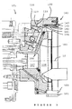
- Figures 1 and 2 show a mandrel 1 comprising a plurality of three identical sets, each comprising a jaw holder 20 equipped with a jaw 30 and equidistributed circumferentially about an axis General 10.
- Figure 2A shows that the jaw holder 20 shown is pressed against a front face 2 of the mandrel body 1 and is held at a radially internal end by a radial crane 21 housed in a radial cavity 3 located behind the front 2.
- the jaw holder 20 has a radial front face 27 receiving and coupling, with possibility of radial sliding, of a face opposite coupling 37 of the jaw 30.
- the jaw 30 is fixed on the jaw holder 20 by two opposite screws 31, 32 with a wide head, whose nearest section of the head is housed freely in a through hole of the jaw 30 presenting, in this example, an elongated cross-section radially with respect to the axis 10, to allow, before screw tightening 31, 32, limited adjustment slip end, or balancing, of the radial distance of the jaw 30, for the purpose of mutual centering of the three jaws 30, as explained later.
- the jaw 30 is equipped with elements, here holes 34, of fixing a form adapter 40, presenting a surface 41, holding a workpiece 60, of shape corresponding overall to a sector around the piece 60 to exert a plurality of holding forces therein distributed.
- the piece 60 presents a cylindrical tubular shape comprising a crown of gear teeth 61 serving for its maintenance.
- the surface 41 for this purpose forms a jaw with teeth globally curved recessed, with extension circumferential with respect to axis 10 and likewise curvature as the toothing 61 but turned towards the axis 10 and covering a specific angular sector.
- the row circumferential teeth of the jaw above, constituting in fact the holding surface 41, can thus mesh with the teeth 61.
- the teeth of the holding surface 41 is constituted by rollers 42 here mounted mobile on respective support shaft rods 43.
- Each support axis 43 is precisely here a section rod substantially circular wheel for rotating the rollers 42, which are so here circular section.
- each support shaft 43 carries several rollers 42 in this example, cylindrical or spherical.
- the axes brackets 43 are inclined with respect to a direction provided the general axis 10 of the chuck, to comply with the inclined orientation of the toothing 61, whose teeth come to live in interstices 49 separating rollers 42 in their row.
- the rollers 42 are mounted above a surface cylindrical counter-support 39 of the jaw 30, or a base of the adapter 40, surface 39 which is turned towards the axis 10 and on which the rollers 42 rest in operation to exert the desired pressure on the workpiece 60.
- the axes supports 43 are resiliently mounted on the jaw 30, or a base of the roller holder 40, so that in a position functional, clamping the workpiece 60, the rollers 42 are radially rejected by the piece to machining 60 against the abutment surface 39, and for that, in a loose position, the rollers 42 are withdrawn from the support surface 39, that is to say towards axis 10.
- each support pin 43 is fixed to the roller holder 40 (Fig. 2A) by a fixing end section resiliently flexible 44, here crimped end in one holes 34, of section adjusted to that of the support axis 43.
- the elastically flexible fastening section 44 further comprises a sub-section 45 for receiving rollers 42, that is to say that the support axis 43 has here elasticity throughout its length.
- Each support shaft 43 comprises an end section free 46 substantially folded at right angles to slide, during the bending of the attachment section 44, 45, in a guide passage 36 formed in the jaw 30, or a base belonging to the adapter 40.
- the support pins 43 In the loosened position, so in the absence of constrained, the support pins 43 occupy a position spaced apart from the counter-support surface 39, which frees the micro-chips possibly present and allows a efficient blowing of these.
- the roller holder 40 here comprises a pin of spatial synchronization 47, occupying a position sectoral predetermined relative to the rollers 42, and having a free end 48 axially forward of rollers 42 for, when setting up the piece to machining 60 in the mandrel in axial advance, meshing, prior to the rollers 42, with the teeth 61 of the piece to be machined 60.
- the jaw holder 20 and the jaw 30 associated respectively comprise the coupling face sliding 27 cooperating with the opposite face of coupling sliding surface 37.
- the sliding coupling face 27 has a first groove 28 for guiding a key 50 of radial distance adjustment of the jaw 30, and the opposite face sliding coupling 37 has a second groove 38 parallel to the first groove 28 (FIG 1) and arranged to receive a lateral appendage 51 of the key 50, actuating elements 52 being associated with the key 50.
- Appendix 51 As the first groove 28 is substantially extended tangential, that is circumferential, with respect to the axis 10, the lateral appendage 51 thus exerts on the bit 30, a radial upward or downward force.
- Appendix 51 has a width equal to that of the second groove 38 to avoid any hysteresis effect during adjustment.
- Appendix 51 is made under the shape of a key, that is to say that the key 50 consists of a single piece by two keys rectilinear contiguous and showing directions mutually inclined extension.
- the operating elements 52 are here a rod removable, possibly a screw, which allows you to push one or other of the ends of the key 50 through two narrow passages extending the first groove 28 to respectively its two ends.
- a screw of back-and-forth adjustment whose inner end, opposite to the control head has a radial return relief, for example a ball, prisoner axially of a cavity end of the key 50, that is to say blocked in relative sliding, but free in rotation. In the direction screwing, the key 50 is thus pushed or pulled.
- the mandrel 1 comprises a plurality of channels 6 of blowing fluid to the holding surface 41 of the adapter 40, for example compressed air, and more precisely towards the bottom of the rollers 42, that is to say towards the counter-support surface 39.
- the channels 6, fed from an axial chamber 107 are distributed according to a conical surface with a vertex facing towards the rear of the mandrel 1 and are placed and directed to orient jets blowing the fluid to the interstices 49 separating the rollers 42 in the row.
- the set consisting of jaw holder 120 and jaws 130, carrying adapters 140 with axes 143 carrying rollers 142 of support surface 141 is arranged to arrange, in an axial zone of radius predetermined limit, a frontal space cavity 108 of receipt of an end section, of reduced diameter, of the workpiece 160.
- the front space 108 represents substantially the conical space bounded by the channels of blowing 106.
- the adapter 140 likewise has a surface of holding 141 with rollers 142 carried by axes 143 with a section fixing end 144, separated by interstices 149.
- the coupling faces 127 and 137, coupled by the key 150 are inclined on a radial to the general axis 10, in a direction of axial advance in away from it, that is to say substantially parallel to the conical surface of distribution of blowing channels 106 fed by the chamber 107. This thus allows to clear axially the bottom of the front cavity 108.
Landscapes
- Engineering & Computer Science (AREA)
- Mechanical Engineering (AREA)
- Gripping On Spindles (AREA)
- Jigs For Machine Tools (AREA)
- Prostheses (AREA)
- Mechanical Coupling Of Light Guides (AREA)
- Television Systems (AREA)
- Pharmaceuticals Containing Other Organic And Inorganic Compounds (AREA)
- Magnetic Resonance Imaging Apparatus (AREA)
Applications Claiming Priority (2)
| Application Number | Priority Date | Filing Date | Title |
|---|---|---|---|
| FR0312137 | 2003-10-17 | ||
| FR0312137A FR2861000B1 (fr) | 2003-10-17 | 2003-10-17 | Adaptateur pour mors |
Publications (2)
| Publication Number | Publication Date |
|---|---|
| EP1524054A1 true EP1524054A1 (de) | 2005-04-20 |
| EP1524054B1 EP1524054B1 (de) | 2009-02-18 |
Family
ID=34355495
Family Applications (1)
| Application Number | Title | Priority Date | Filing Date |
|---|---|---|---|
| EP04292453A Expired - Lifetime EP1524054B1 (de) | 2003-10-17 | 2004-10-15 | Spannbackenadapter |
Country Status (4)
| Country | Link |
|---|---|
| EP (1) | EP1524054B1 (de) |
| AT (1) | ATE422980T1 (de) |
| DE (1) | DE602004019485D1 (de) |
| FR (1) | FR2861000B1 (de) |
Families Citing this family (1)
| Publication number | Priority date | Publication date | Assignee | Title |
|---|---|---|---|---|
| EP2425917B1 (de) * | 2010-09-07 | 2013-08-28 | SMW-AUTOBLOK Spannsysteme GmbH | Membranspannfutter |
Citations (4)
| Publication number | Priority date | Publication date | Assignee | Title |
|---|---|---|---|---|
| GB465855A (en) * | 1936-05-14 | 1937-05-18 | Forkardt Paul Kg | Improvements in or relating to chucks |
| US2543117A (en) * | 1947-03-17 | 1951-02-27 | Mackmann Arthur | Positive drive gear chuck |
| CH339081A (de) * | 1955-02-19 | 1959-06-15 | Spandau Maschf Geco Pumpentech | Einrichtung zum selbsttätigen Einführen eines Zahnrades zwischen die Spannrollen eines Spannfutters |
| US4671520A (en) * | 1984-11-29 | 1987-06-09 | Buderus Ag | Device for holding workpieces during machining operations |
-
2003
- 2003-10-17 FR FR0312137A patent/FR2861000B1/fr not_active Expired - Fee Related
-
2004
- 2004-10-15 DE DE602004019485T patent/DE602004019485D1/de not_active Expired - Lifetime
- 2004-10-15 AT AT04292453T patent/ATE422980T1/de not_active IP Right Cessation
- 2004-10-15 EP EP04292453A patent/EP1524054B1/de not_active Expired - Lifetime
Patent Citations (4)
| Publication number | Priority date | Publication date | Assignee | Title |
|---|---|---|---|---|
| GB465855A (en) * | 1936-05-14 | 1937-05-18 | Forkardt Paul Kg | Improvements in or relating to chucks |
| US2543117A (en) * | 1947-03-17 | 1951-02-27 | Mackmann Arthur | Positive drive gear chuck |
| CH339081A (de) * | 1955-02-19 | 1959-06-15 | Spandau Maschf Geco Pumpentech | Einrichtung zum selbsttätigen Einführen eines Zahnrades zwischen die Spannrollen eines Spannfutters |
| US4671520A (en) * | 1984-11-29 | 1987-06-09 | Buderus Ag | Device for holding workpieces during machining operations |
Also Published As
| Publication number | Publication date |
|---|---|
| ATE422980T1 (de) | 2009-03-15 |
| FR2861000A1 (fr) | 2005-04-22 |
| EP1524054B1 (de) | 2009-02-18 |
| FR2861000B1 (fr) | 2007-01-19 |
| DE602004019485D1 (de) | 2009-04-02 |
Similar Documents
| Publication | Publication Date | Title |
|---|---|---|
| EP0136931B1 (de) | Vorrichtung für die Montage und Demontage von Schleifwerkzeugen auf Maschinen zum Polieren von Stein oder dergleichen | |
| EP0217704B1 (de) | Apparat zum Schaben von Rohroberflächen | |
| FR2727045A1 (fr) | Dispositif de blocage en rotation pour un outil, monte tournant, d'une machine-outil | |
| FR2784916A1 (fr) | Mandrin de serrage a membrane | |
| CH661110A5 (fr) | Structure demontable. | |
| FR2464114A1 (fr) | Dispositif pour le realesage d'arbres creux | |
| FR2738510A1 (fr) | Dispositif de blocage d'article pour la broche d'une machine-outil | |
| EP0828950B1 (de) | Schraube zur schnellen montierung und demontierung, verfahren zur ihrer herstellung und werkzeug zu ihrer demontierung | |
| FR2684579A1 (fr) | Mandrin de serrage pour machine-outil, notamment automatique, et son procede d'obtention. | |
| FR2531887A1 (fr) | Outil de fraisage avec organes de coupe inseres | |
| EP0369488A2 (de) | Werkstückträger mit Teilvorrichtung für numerisch gesteurerte Werkzeugmaschinen | |
| EP0063976B1 (de) | Honwerkzeug | |
| EP1072338B1 (de) | Verfahren und Vorrichtung zum Entfernen von Nieten | |
| WO2013010719A1 (fr) | Dispositif de maintien de pieces mecaniques | |
| EP1524054B1 (de) | Spannbackenadapter | |
| FR2863188A1 (fr) | Mandrin | |
| WO2018178542A1 (fr) | Mandrin de serrage a coulisseaux inclines | |
| EP3682991B1 (de) | Spannring und -hülse mit radialer ausdehnung | |
| EP0285555B1 (de) | Spannvorrichtung eines Werkzeughalters auf einer Spannbasis in einem Bearbeitungszentrum, insbesondere zum Drehen | |
| FR2726215A1 (fr) | Support d'etaux de taille de cles a panneton | |
| EP0864768B1 (de) | Automatische und mikrometrische, selbsthemmende Mutter | |
| EP0913595A1 (de) | Herstellungsverfahren eines Innenringes von einem metallischen Kugelgelenk und so erhaltenes Kugelgelenk | |
| EP1146973B1 (de) | Verformungsverfahren eines rohres in der nähe seiner enden und werkzeug zur durchführung des verfahrens | |
| EP1883486B1 (de) | Werkzeughalterfutter für eine Rotationsmaschine, im Besonderen für einen Schlagschrauber | |
| EP2965844A1 (de) | Verfahren zum herstellen einer spannzange, satz von spannzangenköpfen, spannzangenkopf, und spannzange |
Legal Events
| Date | Code | Title | Description |
|---|---|---|---|
| PUAI | Public reference made under article 153(3) epc to a published international application that has entered the european phase |
Free format text: ORIGINAL CODE: 0009012 |
|
| AK | Designated contracting states |
Kind code of ref document: A1 Designated state(s): AT BE BG CH CY CZ DE DK EE ES FI FR GB GR HU IE IT LI LU MC NL PL PT RO SE SI SK TR |
|
| AX | Request for extension of the european patent |
Extension state: AL HR LT LV MK |
|
| 17P | Request for examination filed |
Effective date: 20051017 |
|
| AKX | Designation fees paid |
Designated state(s): AT BE BG CH CY CZ DE DK EE ES FI FR GB GR HU IE IT LI LU MC NL PL PT RO SE SI SK TR |
|
| GRAP | Despatch of communication of intention to grant a patent |
Free format text: ORIGINAL CODE: EPIDOSNIGR1 |
|
| GRAS | Grant fee paid |
Free format text: ORIGINAL CODE: EPIDOSNIGR3 |
|
| GRAS | Grant fee paid |
Free format text: ORIGINAL CODE: EPIDOSNIGR3 |
|
| RAP1 | Party data changed (applicant data changed or rights of an application transferred) |
Owner name: TOBLER SAS |
|
| GRAA | (expected) grant |
Free format text: ORIGINAL CODE: 0009210 |
|
| AK | Designated contracting states |
Kind code of ref document: B1 Designated state(s): AT BE BG CH CY CZ DE DK EE ES FI FR GB GR HU IE IT LI LU MC NL PL PT RO SE SI SK TR |
|
| REG | Reference to a national code |
Ref country code: GB Ref legal event code: FG4D Free format text: NOT ENGLISH |
|
| REG | Reference to a national code |
Ref country code: CH Ref legal event code: EP |
|
| REG | Reference to a national code |
Ref country code: IE Ref legal event code: FG4D Free format text: LANGUAGE OF EP DOCUMENT: FRENCH |
|
| REF | Corresponds to: |
Ref document number: 602004019485 Country of ref document: DE Date of ref document: 20090402 Kind code of ref document: P |
|
| PG25 | Lapsed in a contracting state [announced via postgrant information from national office to epo] |
Ref country code: FI Free format text: LAPSE BECAUSE OF FAILURE TO SUBMIT A TRANSLATION OF THE DESCRIPTION OR TO PAY THE FEE WITHIN THE PRESCRIBED TIME-LIMIT Effective date: 20090218 Ref country code: SI Free format text: LAPSE BECAUSE OF FAILURE TO SUBMIT A TRANSLATION OF THE DESCRIPTION OR TO PAY THE FEE WITHIN THE PRESCRIBED TIME-LIMIT Effective date: 20090218 Ref country code: ES Free format text: LAPSE BECAUSE OF FAILURE TO SUBMIT A TRANSLATION OF THE DESCRIPTION OR TO PAY THE FEE WITHIN THE PRESCRIBED TIME-LIMIT Effective date: 20090529 Ref country code: NL Free format text: LAPSE BECAUSE OF FAILURE TO SUBMIT A TRANSLATION OF THE DESCRIPTION OR TO PAY THE FEE WITHIN THE PRESCRIBED TIME-LIMIT Effective date: 20090218 |
|
| NLV1 | Nl: lapsed or annulled due to failure to fulfill the requirements of art. 29p and 29m of the patents act | ||
| PG25 | Lapsed in a contracting state [announced via postgrant information from national office to epo] |
Ref country code: AT Free format text: LAPSE BECAUSE OF FAILURE TO SUBMIT A TRANSLATION OF THE DESCRIPTION OR TO PAY THE FEE WITHIN THE PRESCRIBED TIME-LIMIT Effective date: 20090218 Ref country code: SE Free format text: LAPSE BECAUSE OF FAILURE TO SUBMIT A TRANSLATION OF THE DESCRIPTION OR TO PAY THE FEE WITHIN THE PRESCRIBED TIME-LIMIT Effective date: 20090518 Ref country code: PL Free format text: LAPSE BECAUSE OF FAILURE TO SUBMIT A TRANSLATION OF THE DESCRIPTION OR TO PAY THE FEE WITHIN THE PRESCRIBED TIME-LIMIT Effective date: 20090218 |
|
| REG | Reference to a national code |
Ref country code: IE Ref legal event code: FD4D |
|
| PG25 | Lapsed in a contracting state [announced via postgrant information from national office to epo] |
Ref country code: CZ Free format text: LAPSE BECAUSE OF FAILURE TO SUBMIT A TRANSLATION OF THE DESCRIPTION OR TO PAY THE FEE WITHIN THE PRESCRIBED TIME-LIMIT Effective date: 20090218 Ref country code: EE Free format text: LAPSE BECAUSE OF FAILURE TO SUBMIT A TRANSLATION OF THE DESCRIPTION OR TO PAY THE FEE WITHIN THE PRESCRIBED TIME-LIMIT Effective date: 20090218 Ref country code: IE Free format text: LAPSE BECAUSE OF FAILURE TO SUBMIT A TRANSLATION OF THE DESCRIPTION OR TO PAY THE FEE WITHIN THE PRESCRIBED TIME-LIMIT Effective date: 20090218 Ref country code: PT Free format text: LAPSE BECAUSE OF FAILURE TO SUBMIT A TRANSLATION OF THE DESCRIPTION OR TO PAY THE FEE WITHIN THE PRESCRIBED TIME-LIMIT Effective date: 20090727 Ref country code: DK Free format text: LAPSE BECAUSE OF FAILURE TO SUBMIT A TRANSLATION OF THE DESCRIPTION OR TO PAY THE FEE WITHIN THE PRESCRIBED TIME-LIMIT Effective date: 20090218 |
|
| PG25 | Lapsed in a contracting state [announced via postgrant information from national office to epo] |
Ref country code: RO Free format text: LAPSE BECAUSE OF FAILURE TO SUBMIT A TRANSLATION OF THE DESCRIPTION OR TO PAY THE FEE WITHIN THE PRESCRIBED TIME-LIMIT Effective date: 20090218 Ref country code: SK Free format text: LAPSE BECAUSE OF FAILURE TO SUBMIT A TRANSLATION OF THE DESCRIPTION OR TO PAY THE FEE WITHIN THE PRESCRIBED TIME-LIMIT Effective date: 20090218 |
|
| PLBE | No opposition filed within time limit |
Free format text: ORIGINAL CODE: 0009261 |
|
| STAA | Information on the status of an ep patent application or granted ep patent |
Free format text: STATUS: NO OPPOSITION FILED WITHIN TIME LIMIT |
|
| 26N | No opposition filed |
Effective date: 20091119 |
|
| PG25 | Lapsed in a contracting state [announced via postgrant information from national office to epo] |
Ref country code: BG Free format text: LAPSE BECAUSE OF FAILURE TO SUBMIT A TRANSLATION OF THE DESCRIPTION OR TO PAY THE FEE WITHIN THE PRESCRIBED TIME-LIMIT Effective date: 20090518 |
|
| BERE | Be: lapsed |
Owner name: TOBLER SAS Effective date: 20091031 |
|
| PG25 | Lapsed in a contracting state [announced via postgrant information from national office to epo] |
Ref country code: MC Free format text: LAPSE BECAUSE OF NON-PAYMENT OF DUE FEES Effective date: 20091031 |
|
| REG | Reference to a national code |
Ref country code: CH Ref legal event code: PL |
|
| REG | Reference to a national code |
Ref country code: FR Ref legal event code: ST Effective date: 20100630 |
|
| PG25 | Lapsed in a contracting state [announced via postgrant information from national office to epo] |
Ref country code: FR Free format text: LAPSE BECAUSE OF NON-PAYMENT OF DUE FEES Effective date: 20091102 |
|
| PG25 | Lapsed in a contracting state [announced via postgrant information from national office to epo] |
Ref country code: BE Free format text: LAPSE BECAUSE OF NON-PAYMENT OF DUE FEES Effective date: 20091031 Ref country code: LI Free format text: LAPSE BECAUSE OF NON-PAYMENT OF DUE FEES Effective date: 20091031 Ref country code: GR Free format text: LAPSE BECAUSE OF FAILURE TO SUBMIT A TRANSLATION OF THE DESCRIPTION OR TO PAY THE FEE WITHIN THE PRESCRIBED TIME-LIMIT Effective date: 20090519 Ref country code: CH Free format text: LAPSE BECAUSE OF NON-PAYMENT OF DUE FEES Effective date: 20091031 |
|
| PG25 | Lapsed in a contracting state [announced via postgrant information from national office to epo] |
Ref country code: LU Free format text: LAPSE BECAUSE OF NON-PAYMENT OF DUE FEES Effective date: 20091015 |
|
| PG25 | Lapsed in a contracting state [announced via postgrant information from national office to epo] |
Ref country code: HU Free format text: LAPSE BECAUSE OF FAILURE TO SUBMIT A TRANSLATION OF THE DESCRIPTION OR TO PAY THE FEE WITHIN THE PRESCRIBED TIME-LIMIT Effective date: 20090819 |
|
| PG25 | Lapsed in a contracting state [announced via postgrant information from national office to epo] |
Ref country code: TR Free format text: LAPSE BECAUSE OF FAILURE TO SUBMIT A TRANSLATION OF THE DESCRIPTION OR TO PAY THE FEE WITHIN THE PRESCRIBED TIME-LIMIT Effective date: 20090218 |
|
| PG25 | Lapsed in a contracting state [announced via postgrant information from national office to epo] |
Ref country code: CY Free format text: LAPSE BECAUSE OF FAILURE TO SUBMIT A TRANSLATION OF THE DESCRIPTION OR TO PAY THE FEE WITHIN THE PRESCRIBED TIME-LIMIT Effective date: 20090218 |
|
| PGFP | Annual fee paid to national office [announced via postgrant information from national office to epo] |
Ref country code: DE Payment date: 20120926 Year of fee payment: 9 |
|
| PGFP | Annual fee paid to national office [announced via postgrant information from national office to epo] |
Ref country code: GB Payment date: 20121025 Year of fee payment: 9 Ref country code: IT Payment date: 20120927 Year of fee payment: 9 |
|
| GBPC | Gb: european patent ceased through non-payment of renewal fee |
Effective date: 20131015 |
|
| PG25 | Lapsed in a contracting state [announced via postgrant information from national office to epo] |
Ref country code: GB Free format text: LAPSE BECAUSE OF NON-PAYMENT OF DUE FEES Effective date: 20131015 |
|
| REG | Reference to a national code |
Ref country code: DE Ref legal event code: R119 Ref document number: 602004019485 Country of ref document: DE Effective date: 20140501 |
|
| PG25 | Lapsed in a contracting state [announced via postgrant information from national office to epo] |
Ref country code: IT Free format text: LAPSE BECAUSE OF NON-PAYMENT OF DUE FEES Effective date: 20131015 Ref country code: DE Free format text: LAPSE BECAUSE OF NON-PAYMENT OF DUE FEES Effective date: 20140501 |