EP1524074A1 - Régulation du mouvement d'un dispositif de polissage pour des pierres précieuses - Google Patents
Régulation du mouvement d'un dispositif de polissage pour des pierres précieuses Download PDFInfo
- Publication number
- EP1524074A1 EP1524074A1 EP04256273A EP04256273A EP1524074A1 EP 1524074 A1 EP1524074 A1 EP 1524074A1 EP 04256273 A EP04256273 A EP 04256273A EP 04256273 A EP04256273 A EP 04256273A EP 1524074 A1 EP1524074 A1 EP 1524074A1
- Authority
- EP
- European Patent Office
- Prior art keywords
- polishing
- rod
- tang
- vertical rod
- movement
- Prior art date
- Legal status (The legal status is an assumption and is not a legal conclusion. Google has not performed a legal analysis and makes no representation as to the accuracy of the status listed.)
- Granted
Links
- 238000005498 polishing Methods 0.000 title claims abstract description 136
- 239000010437 gem Substances 0.000 title description 55
- 229910001751 gemstone Inorganic materials 0.000 title description 49
- 230000003213 activating effect Effects 0.000 claims abstract description 12
- 210000000078 claw Anatomy 0.000 claims description 9
- 230000007246 mechanism Effects 0.000 description 19
- 241001422033 Thestylus Species 0.000 description 13
- 238000007517 polishing process Methods 0.000 description 13
- 239000010432 diamond Substances 0.000 description 12
- 238000000034 method Methods 0.000 description 11
- 229910003460 diamond Inorganic materials 0.000 description 10
- 230000003534 oscillatory effect Effects 0.000 description 6
- 230000008569 process Effects 0.000 description 6
- 230000004048 modification Effects 0.000 description 4
- 238000012986 modification Methods 0.000 description 4
- 239000004575 stone Substances 0.000 description 4
- 229910001018 Cast iron Inorganic materials 0.000 description 2
- XEEYBQQBJWHFJM-UHFFFAOYSA-N Iron Chemical compound [Fe] XEEYBQQBJWHFJM-UHFFFAOYSA-N 0.000 description 2
- 230000000712 assembly Effects 0.000 description 2
- 238000000429 assembly Methods 0.000 description 2
- 230000008878 coupling Effects 0.000 description 2
- 238000010168 coupling process Methods 0.000 description 2
- 238000005859 coupling reaction Methods 0.000 description 2
- 238000010586 diagram Methods 0.000 description 2
- 239000000463 material Substances 0.000 description 2
- 230000010355 oscillation Effects 0.000 description 2
- 230000008929 regeneration Effects 0.000 description 2
- 238000011069 regeneration method Methods 0.000 description 2
- XLYOFNOQVPJJNP-UHFFFAOYSA-N water Substances O XLYOFNOQVPJJNP-UHFFFAOYSA-N 0.000 description 2
- 241000238413 Octopus Species 0.000 description 1
- 230000004913 activation Effects 0.000 description 1
- 150000001875 compounds Chemical class 0.000 description 1
- 239000004020 conductor Substances 0.000 description 1
- 230000001747 exhibiting effect Effects 0.000 description 1
- 239000012212 insulator Substances 0.000 description 1
- 229910052742 iron Inorganic materials 0.000 description 1
- 238000004519 manufacturing process Methods 0.000 description 1
- 239000002184 metal Substances 0.000 description 1
- 229910052751 metal Inorganic materials 0.000 description 1
- 239000000615 nonconductor Substances 0.000 description 1
- 239000000843 powder Substances 0.000 description 1
- 239000002994 raw material Substances 0.000 description 1
- 238000006748 scratching Methods 0.000 description 1
- 230000002393 scratching effect Effects 0.000 description 1
Images






Classifications
-
- B—PERFORMING OPERATIONS; TRANSPORTING
- B24—GRINDING; POLISHING
- B24B—MACHINES, DEVICES, OR PROCESSES FOR GRINDING OR POLISHING; DRESSING OR CONDITIONING OF ABRADING SURFACES; FEEDING OF GRINDING, POLISHING, OR LAPPING AGENTS
- B24B9/00—Machines or devices designed for grinding edges or bevels on work or for removing burrs; Accessories therefor
- B24B9/02—Machines or devices designed for grinding edges or bevels on work or for removing burrs; Accessories therefor characterised by a special design with respect to properties of materials specific to articles to be ground
- B24B9/06—Machines or devices designed for grinding edges or bevels on work or for removing burrs; Accessories therefor characterised by a special design with respect to properties of materials specific to articles to be ground of non-metallic inorganic material, e.g. stone, ceramics, porcelain
- B24B9/16—Machines or devices designed for grinding edges or bevels on work or for removing burrs; Accessories therefor characterised by a special design with respect to properties of materials specific to articles to be ground of non-metallic inorganic material, e.g. stone, ceramics, porcelain of diamonds; of jewels or the like; Diamond grinders' dops; Dop holders or tongs
- B24B9/167—Machines or devices designed for grinding edges or bevels on work or for removing burrs; Accessories therefor characterised by a special design with respect to properties of materials specific to articles to be ground of non-metallic inorganic material, e.g. stone, ceramics, porcelain of diamonds; of jewels or the like; Diamond grinders' dops; Dop holders or tongs with means for turning and positioning the gem stones
Definitions
- the present invention relates to a device for controlling the movement of a polishing assembly during the polishing process of precious. stones, gems, semi-precious stones and the like.
- the present invention also provides a device having an oscillating and lifting mechanism enabling the user to control the movement of polishing assembly during use, ensuring repeatability of the polishing process.
- the value of a jewelry gemstones increases as they pass through the fashioning process from rough raw material to finished brilliants.
- the gemstone manufacturing process typically comprises one or more of the following steps: cleaving, splitting or sawing of the rough gemstones; bruting of the rough gemstones; grinding of the gemstones and polishing the facets.
- This invention relates in particular to the two last steps of grinding and polishing.
- the gemstone. is faceted by using a polishing assembly, also called a tang that comprises an adjustable polishing gemstone holder, or dop fitted at the end of a stylus at one end of the tang.
- the gemstone to be grinded. or polished is set in a metal collet or in a crown pot and claw assembly set in an adjustable dop, which is set at a given angle, and index (radial position) via the tang onto the scaife, a polishing wheel.
- a scaife is typically a flat cast-iron wheel coated with, for example, diamond powder.
- the surface of the scaife may also comprise several sections with different polishing compounds to be used at different stages of the polishing process.
- This polishing wheel is driven by a motor and revolves about a vertical axis. More than one polishing assembly (tang) can be used at the same time on the same scaife. By oscillating the tang on a given portion of the scaife, a facet of a given shape is produced.
- the grinding of gemstones comprising two steps: first, the cross-work, whereby the table facet, eight pavilion facets and eight crown facets are ground; and followed by the step of brillianteering, whereby through continuous adjustment of the dop, the remaining facets are placed on the edges of the established main facets.
- the adjustment of the dop is determined with reference to the position of the previous polished facet and the shape of the gemstone.
- the polishing process has to be interrupted at regular intervals in order to check the polishing depth reached and the quality of the facet obtained. This task demands great skill in order to obtain the correct polishing depth for a particular facet.
- polishing assembly is moved across the scaife.
- the movement of the assembly (tang) is controlled by hand, and care must be used to ensure that the correct portion of the tang and dop is being used for a given step in the grinding or polishing process.
- the proper size of the facet must be determined during the process and the progress of the grinding or polishing operation has to be repeatedly interrupted in order to check the grinding and polishing depth reached.
- Careless grinding and polishing may result in the scaife surface becoming scratched and grooved.
- a scratched polishing wheel in turn causes deep grooves on the gemstone and possibly subsequent loss of gemstone value. Due to the nature of the manual operation, the results of the grinding and polishing process may be inconsistent, resulting poor repeatability of the operation.
- US 4,603,512 discloses an apparatus for lapping a facet at the tip of a stylus by softly setting the tip down on a rotating scaife, and for determining the correct depth of polishing of the diamond.
- the stylus having a diamond tip bonded to a metallic dop is placed in contact with the surface of a rotating electrically conducting scaife and a current is established between the stylus and the scaife.
- a detector coupled to the stylus determines when the diamond tip is sufficiently lapped, and the control signal is used to actuate a mechanism for lifting or removing the stylus tip from contact the scaife and thereby cease lapping the stylus.
- Two devices for controlling movement of a polishing assembly are commercially available.
- the second device controls lateral sliding movement of the tang, and hence the movement of the stylus, across the scaife.
- Both products can be added to existing polishing equipment.
- two pieces of equipment are needed for controlling movement of a tang (see, for example, product catalogues from Bettonville NV, Antwerp; Rico Tools NV, Herenthout; Adri Diamond Tools, Grobbendonk, all in Belgium).
- EP 0,299,692 describes an apparatus and method for operating the scaife at a speed above its radical critical frequency to achieve stable operation.
- EP 0945217 describes an apparatus for faceting gems comprising a vertical supporting plate to guide the movement of the gemstone on dop sticks.
- US 4,254,587 relates to a device that holds a stone in contact with an abrading surface for grinding the stone.
- the stone is moved continuously across the surface of the polishing wheel to avoiding grooving of the abrading surface.
- the present invention relates to a device for controlling the movement of a polishing assembly during the grinding process of gemstones.
- the present invention also provides a device having an oscillating and lifting mechanism enabling the user to control the movement of polishing assembly during use, ensuring repeatability of the of the polishing process.
- a device for controlling movement of a polishing assembly comprising, a vertical rod; one or more than one motive power means for lowering and lifting, and rotating or oscillating the vertical rod about an axis of rotation coaxial with the vertical rod; a pin offset from the axis of rotation and connected to the vertical rod for mounting the polishing assembly.
- the present invention also pertains to the device defined above, wherein the device controls oscillating movement of the polishing assembly (tang) on a polishing wheel.
- the present invention provides a device as defined above, wherein the pin is attached to an adjustable adaptor, and the adjustable adaptor is fastened to the vertical rod.
- the adjustable adaptor may be fitted with.a spring-loaded collar for gradual transferring of weight of the polishing assembly to a polishing wheel.
- the device may comprise a guide, the guide defining an opening through which the vertical rod is inserted.
- the present invention also embraces the device defined above, wherein an electronic controller is operatively connected to the one or more than one mechanism.
- the electronic controller may control lowering and lifting, rotating or oscillating movement of the vertical rod, or the electronic controller may control lifting and lowering movement of the rod.
- the speed of lowering and raising the vertical rod may be set by the electronic controller.
- the present invention also relates to a device for controlling polishing assembly movement comprising, a vertical rod; one or more than one motive power means for lowering and lifting, and rotating or oscillating the vertical rod about an axis of rotation coaxial with the vertical rod; a pin offset from the axis of rotation and connected to the vertical rod for mounting the polishing. assembly, and a sensor for activating movement of the vertical rod.
- the present invention also provides the device as just defined, wherein the sensor is operatively communicatng with a dop within the polishing assembly.
- the sensor may be an electrical circuit, and contact of the dop with a polishing wheel closes the electrical circuit so that the vertical rod is lifted off of the polishing wheel surface.
- the device for controlling polishing arm movement of the present invention is easy to operate, permits accurate grinding of gemstones, saves time in polishing gemstones, and permits a user to oversee a plurality of active polishing assemblies at the same time.
- the design ensures consistency and repeatability of the polishing operation. Furthermore, it improves the longevity of the collet and/or claws holding the gemstone in the dop and associated stylus as the tang is lifted off the wheel once the appropriate facet depth is obtained thereby minimizing wear of the collet, claw or both the collet and claw in the dop.
- the device of the present invention also increases longevity of the polishing wheel, because the gemstone is moved over an optimized.
- FIGURE 1 shows a front perspective view of the device in accordance with an embodiment of the present invention.
- FIGURE 2 shows a front view of the device in accordance with an embodiment of the present invention.
- FIGURE 3 shows a top view of the lower portion of the device in accordance with an embodiment of the present invention, with the base plate removed. Showing the motor drives (145, 150), cam (160) and oscillating member (165).
- FIGURE 4 shows a side view of the device in accordance with an embodiment of the present invention.
- FIGURE 5 shows a bottom view of the device in accordance with an embodiment of the present invention.
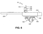
- FIGURE 6 shows a cross section of a portion of the polishing table (210) and scaife (220), and a side view of the device (10) in accordance with an embodiment of the present invention.
- FIGURE 7 shows a top perspective view of the device (10) in accordance with an embodiment of the present invention in relation to a polishing wheel (220) and part of a polishing table (210).
- FIGURE 8 shows a schematic of a wiring diagram of the device in accordance with an embodiment of the present invention.
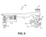
- FIGURE 9 shows a non-limiting example of a side view of a polishing assembly (tang; 20).
- FIGURE 10 shows a non-limiting example of a side view of a polishing table with the tang and the device of the present invention removed.
- FIGURE 11 shows a part of the underside of a polishing assembly (tang 20) in accordance with an embodiment of the present invention, having a plurality of recesses each of which may receive the pin (not shown) of the device of the present invention.
- FIGURE 12 shows a modified end of a polishing assembly (tang; 20) in accordance with an embodiment of the present invention, with two wheels.
- the present invention relates to a device for controlling the movement of a polishing assembly during the polishing process of gemstones.
- the present invention also provides a device having an oscillating and lifting mechanism enabling the user to control the movement of grinding and polishing assembly during use, ensuring repeatability of the of the polishing process.
- the present invention provides a device for controlling movement of a polishing assembly or tang, used during gemstone polishing.
- the device of the present invention comprises a vertical rod (130) with a first end (90) and a second end (80), a mechanism for lifting and lowering the vertical rod, (see for example, but not limited to, elements 150, and 160), and a mechanism for rotating the vertical rod about an axis of rotation (for example, but not limited to 145, 165 and 185).
- a pin (135), or similar member, is provided for mounting the polishing assembly (not shown, also referred to as a tang, 20; see Figure 9) to the device of the present invention (10).
- the pin (135) is associated with the vertical rod (130) and is offset from the axis of rotation (shown as line A-A in Figure 1), so that when the vertical rod either rotates, oscillates or both rotates and oscillates, the pin moves accordingly about the same axis.
- the device of the present invention may be used with any tang (20), as is known in the art, for example as shown in Figure 9, and any gemstone polishing table (30; see Figure 10), as is known is the art, with a motor (230); a motor switch (310); a frame (320); a drawer (340); a sleigh (350) and a tang rack (360).
- the pin (135) with its sleeve (140) may be attached to the vertical rod (130) via an adaptor (125).
- the adaptor (125) may be fixedly attached to the vertical rod (135), and its position along the vertical rod adjustable prior to being engaged with the vertical rod via any suitable mechanism, for example but not limited to a key, bolt, spring clip, snap ring, or other mechanism permitting adjustment of the height, and fixing the position, of the pin assembly along the rod.
- the pin may also be continuous with the vertical rod, and the vertical position of the pin adjusted by positioning and registering the shaft of vertical rod with respect to the surface of the table, for example using a sleeve that may be attached to the rod and that abuts the table to determine the height adjustment of the pin.
- Alternate methods of interfacing the pin (135) with the tang include for example, but not limited to, a ball and socket joint, a universal joint, or other mechanism that permits a rotational or oscillatory, as well as a vertical movement of the pin (135) and tang, when the pin is registered with the tang.
- the device (10) may be mounted to a polishing table (see Figure 10) so that the one or more than one motor drive (150 and 145) is housed below the table surface, and the vertical rod (130) extends up through an opening in the table surface, and the offset pin (135) positioned to interface with a polishing assembly (tang).
- a polishing table see Figure 10
- the motor drives (150, 145) and the vertical rod (130) may be placed on top of the table, or alternatively, the motor drive may be placed away from the polishing table, and communicate with one or more than one vertical rod by any appropriate linkage elements, for example using a chain, belt or rods as appropriate.
- one or more than one polishing assembly (tang), and associated devices (10) of the present invention may be mounted to a polishing table.
- the one or more than one motor drive below or off the table surface, utilization of space on the polishing table is minimized, and permits additional tangs to be used per scaife.
- the device (10) of the present invention may comprise a base plate (100) for supporting component parts of the device as shown in Figures 4 and 5.
- the base plate may be used for mounting the device (10) to the polishing table (210; Figure 6).
- the components of the device that are shown attached to the base plate (100), in Figure 1-5 maybe each separately attached to the polishing table, for example the undersurface or top surface of the polishing table.
- One or more than one motor drive (e.g. 145, 150) or linkages (165) may be attached to the base plate, for example using a bracket (155, 180), elongated nuts (105, 106) or other attachment device.
- the one or more than one motor drive (150,145) may be any suitable motor, powered manually, electrically or via other means for example, compressed air.
- a non-limiting example of a motor drive is a linear stepper motor. As shown in Figure 1, there may be two motor drives one motor drive (150) that interfaces with the second end (80) of the vertical rod (130) so that when the drive is actuated, the vertical rod moves up and down, and a second drive (145) that imparts an oscillatory or rotational movement to the vertical rod (130) via linkage (165).
- FIG. 1 A non-limiting example of a mechanism for imparting the up and down motion to the vertical rod is shown in Figure 1, where the shaft (176) of the linear step motor (150) is in contact with a pivoting cam (160, via end 173).
- the cam oscillates around a pivot point (85) and raises or lowers the vertical rod, respectively.
- the cam may be positioned relative to the base (100) via bracket (180).
- the stepper motor maybe placed in direct association with the vertical rod, so that as the shaft (176) of the motor (150) extends and retracts, the vertical rod (130) is raised and lowered, respectively.
- the linear stepper motor (150) retracts shaft (176), and the cam (160) rotates towards the stepper motor (150) so that the vertical rod (130) is lowered.
- the vertical rod is interfaced with a polishing assembly (tang), via pin (135) the gemstone attached to the stylus of the tang is brought into contact with the scaife in a controlled and gentle manner, thereby eliminating scratching of the polishing wheel.
- This automatic, gentle lowering process permits the user to attend to other process involved in the polishing process, for example, the polishing assembly may be advanced to a next position, or additional tangs on the polishing table may be adjusted as required.
- Alternate mechanisms to raise and lower the vertical rod may also be used, for example, an eccentric rotating cam, that rotates around the same axis of rotation as a rotating shaft of a stepper motor, may be used to raise and lower the vertical rod; an electrical solenoid that when activated raises and lowers the rod, or an electromagnet that when activated raises or lowers the vertical rod, as would be known to one of skill in the art.
- the adaptor (125) may comprise a spring assembly (not shown), which holds some of the weight of the polishing assembly (the tang) when it is positioned upon the pin. As the tang is lowered and the stylus contacts the scaife, the weight of the load of the tang is gradually transferred from the spring within the adaptor and onto the scaife, providing a gentle motion when the gemstone is brought in contact with the wheel.
- the speed of raising and lowering the vertical rod may be controlled so that when a polishing assembly (tang) that is positioned on pin (135) is lowered onto the scaife, the gemstone positioned at the stylus of the tang meets the scaife in a gradual and controlled manner.
- a polishing assembly tang
- pin (135) When the surface of the gemstone is sufficiently polished, it may be desired to raise the vertical rod in an efficient, accelerated manner minimizing any over polishing of a surface of the gemstone.
- the vertical rod (130) also rotates, oscillates, or both rotates and oscillates around a vertical axis (A-A, see Figures 1 and 2), thereby imparting a horizontal movement to pin (135).
- the second stepper motor (145) can provide the rotational or oscillating movement to the vertical rod (130), through the link (165), and to pin (135). This movement is further transferred to a polishing assembly, when attached to pin (135), to provide a controlled movement, either rotational or actuate, to the gemstone when the gem stone is in contact with the face of a rotating polishing wheel (scaife).
- This oscillating movement allows the use of the different zones of the abrasive charged surface of the polishing wheel while at the same time avoiding grooving of the polishing wheel.
- tang (20); an example of a tang is shown in Figure 9) is registered against pin (135), and the pin rotates, oscillates, or both, the tang will move across the surface of a scaife in a similar horizontal manner.
- the rotational or oscillatory movement of the pin is provided via a motive drive, for example, motor drive (145), which can also be a stepper motor.
- Rotational or oscillatory movement of the shaft of drive (145) may be imparted to vertical rod (135) either directly, via a direct drive motor drive, or via a linkage mechanism, for example, but not limited to a mechanism shown in the non-limiting Figures 1-4, comprising a first coupler (190), coupling a wheel (170) attached to a shaft of the motor drive (145) to arm (165), and a second coupler (185), coupling the arm (165) to the vertical rod.
- a linkage mechanism for example, but not limited to a mechanism shown in the non-limiting Figures 1-4, comprising a first coupler (190), coupling a wheel (170) attached to a shaft of the motor drive (145) to arm (165), and a second coupler (185), coupling the arm (165) to the vertical rod.
- the motor drive (145) may impart an oscillatory movement to the vertical rod (130).
- the drive mechanism can be configured so that a rotational movement is delivered to the vertical rod, for example by placing the motor and linkage assembly (145, 170, 190, 165, 185) below the plane of motor drive (150) and cam (160).
- the linkage mechanism may also comprise chain or belts that transfer the rotational or oscillatory movement from motor drive (145) to the vertical rod.
- the rod may be positioned within a guide (110, Figures 1-4).
- the guide maybe placed on the base plate (100) and pass through the polishing table (210) typically in the proximity of the scaife (220), or it may be affixed to the top surface of the polishing table.
- an electrical operational controller controls the depth of the grinding and polishing process by detecting the extent of polishing of a non-conductive gemstone surface.
- a non-conductive gemstone surface For example, which is not to be considered limiting in any manner, diamonds are well known for exhibiting high electrical resistivity (10 15 Ohm/cm) and low dielectric constant. Other gemstones may also exhibit similar properties.
- the polishing wheel (scaife, 220) and the polishing arm assembly (tang; shown schematically in Figure 8 as 20) may therefore be connected to opposite poles of a power source, for example but not limited to a low voltage (6 to 12 volt) direct current power source, or a regular (110, 210 volt) power source, in such a way that the non-conductive gemstone, mounted on the press pot of the stylus acts as an insulator to keep the circuit open.
- the tang may connected to this circuit through vertical rod (130).
- the non-conductive gemstone is polished until a point when the press pot, or other component of the tang makes contact with the iron scaife, thereby closing the electrical circuit.
- a collet would be used to hold the diamond in position in the dop. In this case the collet becomes the contact point where the circuit would be closed.
- the claw would be set in the appropriate position and the claw would become the contact point for the closing of the circuit.
- the electrical operational controller (260) that activates a lifting circuit.
- the lifting circuit may involve stopping the oscillating motor (145), and activating motor drive (150) to extend shaft (176; Figures 1, 3, 4 and 5) to lift the vertical rod (130), pin (135), the interfaced polishing arm assembly (20), and stylus off the scaife (220), and prevent any further polishing of the non-conductive gemstone.
- the device may also have a home switch (240) to control the overall operation.
- the lifting, lowering, rotation or oscillation of the vertical rod (130), and associated components may also be effected through activating switch 120 ( Figures 1, 2, 4 and 8).
- the gemstone is reset within the stylus, the vertical rod, and tang may be lowered onto the scaife using activating switch 120, and associated components as described below.
- the electrical. operational controller (260) may also be used for controlling the operation of the motor drives (145, 150), including lifting, lowering, and the rate of oscillation.
- the electrical operational controller may also allow the adjustment of the ratio between the lowering speed and the lifting speed.
- a gentle, slow lowering speed of vertical rod (130) results in a slow lowering of polishing assembly and ensures a smooth touch down of the gemstone onto the polishing wheel.
- the lowering speed of the vertical rod (130) may also be controlled via a spring mechanism that is slowly compressed by weight of the polishing assembly (tang) as the cam (160) is pivoted towards the shaft (176) and motor drive (150) body.
- an air piston or other mechanism as would be evident to one of skill in the art, may be used to slow the downward movement of the vertical rod when the polishing assembly (tang) is being lowered and brought into contact with the scaife.
- the activating switch (120) may be positioned anywhere that is convenient for use and where it may be easily actuated. This switch may also be located off the polishing table if desired.
- the activating switch (120) may be used to activate the first drive motor (150) to retract shaft (176), cam (160) thereby allowing vertical rod (130) to lower in a controlled manner, as described above, and permit the gemstone in association with the tang to be brought in contact with the scaife.
- the activating switch (120) may also be used to raise the vertical rod (130) and interfaced tang, by activating motor drive (150) to extend shaft (176), and pivot cam (160), to raise the vertical rod.
- the schematic shown in figure 8 utilizes a sensor that detects the closing or opening of the circuit established between the scaife (220) and the tang (20), when used in conjunction with a non-conductive gemstone, for example but not limited to a diamond.
- a non-conductive gemstone for example but not limited to a diamond.
- the diamond polishing process utilizes a dry scaife, turning at high speed which helps insure that the circuit is open or closed as the case may be.
- other gemstones may be conductive, or their polishing and grinding process may use water and a lap (scaife) turning at slow speeds. Water, or a conductive gemstone may eliminate the insulating qualities required for this circuit as described above to function. Therefore, alternate methods of sensing the required degree of grinding and polishing may be used.
- a beam of light traveling from a source to a detector may be intercepted, or the light may be reflected to a detector, by the tang frame or other component of the tang, as the component reaches a certain height off the polishing table or scaife.
- the interception or reflection of the light beam may then active the lifting circuit as described above.
- Other sensor type mechanism may also be utilized to active movement of the vertical rod (130) as would be known by one of skill in the art, for example activation of the lifting circuit as a result of time.
- the lifting circuit may also be activated by the user as required using activating switch 120.
- the device (10) of the present invention may be used with any polishing assembly (tang), including but not limited to, a Quickstep Tang (Crown, see Figure 9).
- tang typically comprises at a first end a stylus comprising a dop that retains the gemstone for polishing, and at the second end a guide or support members that may ride on a sleigh mounted on the polishing table, or the guide may simply ride on the table surface itself.
- Figure 9 shows a non-limiting example of a tang (polishing arm; 20), in this case a Quickstep tang.
- a tang typically comprises a frame (1); a subframe (2); adjusting legs (3); an adjustable spirit level (5); a height adjuster (10); and an indexed crown dop comprising: an angle adjuster (6); and index adjuster (7); an index wheel (8); a dop assembly (9); an angle gauge (11) and a claw holder (4).
- variations in the components of a tang are common.
- the arm of the tang may be modified to include a plurality of recess, each which may be selected to accept the pin (135) of the device (10) of the present invention. See for example Figure 11, which shows the underside of the arm (1) of a tang comprising four recesses (250).
- the pin (135) may register with the polishing assembly (tang) at any one of these several recesses (250) in the arm.
- the movement of the tang across the scaife can be modified. Alternate modifications, as would be evident to one of skill in the art, may also be made to the tang to receive pin (135).
- Modification of the second end of the tang may be desired to ensure that the tang moves freely when interfaced with the device (10) of the present invention. Modification may include replacing the guide (for example the adjusting leg, 3) at the second end of the tang with one or more than one rollers, for example two rollers (270) as shown in Figure 12, to permit smooth movement of the tang across the surface of the polishing table.
- the rollers may be made of electrical insulator such as plastic, so that the tang is insulated from the polishing table (210) if a control circuit, as outlined in Figure 8, comprising one pole connected to the scaife (220), and a second pole connected to the vertical rod (130), the tang (20), and the stylus is used.
- One or more than one cylindrical or ball roller may be used for this purpose. However, if the guide or adjusting leg (3) moves freely over the table surface, replacement may not be required. Additionally, as previously described, the tang frame may be modified to receive the pin (135) so that any movement imparted by the pin is effectively transferred to the tang, including both vertical and horizontal movements.
- the device (10) for controlling polishing arm movement of the present invention is easy to operate, permits accurate polishing of gemstones, saves time in polishing gemstones, and permits a user to oversee a plurality of active polishing assemblies at the same time.
- the design ensures consistency and repeatability of the polishing operation. Furthermore, it improves the longevity of the parts retaining the gemstone as the polishing assembly (tang) is lifted off the wheel once the appropriate depth of polish is obtained, and increase longevity of the polishing wheel, because the gemstone is moved over an optimized area of the scaife during polishing and less material needs to be removed during regeneration of the polishing wheel.
Landscapes
- Engineering & Computer Science (AREA)
- Chemical & Material Sciences (AREA)
- Ceramic Engineering (AREA)
- Inorganic Chemistry (AREA)
- Mechanical Engineering (AREA)
- Finish Polishing, Edge Sharpening, And Grinding By Specific Grinding Devices (AREA)
- Grinding And Polishing Of Tertiary Curved Surfaces And Surfaces With Complex Shapes (AREA)
Applications Claiming Priority (2)
| Application Number | Priority Date | Filing Date | Title |
|---|---|---|---|
| CA002445030A CA2445030C (fr) | 2003-10-14 | 2003-10-14 | Dispositif de controle du mouvement de polissage de pierres precieuses |
| CA2445030 | 2003-10-14 |
Publications (2)
| Publication Number | Publication Date |
|---|---|
| EP1524074A1 true EP1524074A1 (fr) | 2005-04-20 |
| EP1524074B1 EP1524074B1 (fr) | 2008-04-09 |
Family
ID=32046604
Family Applications (1)
| Application Number | Title | Priority Date | Filing Date |
|---|---|---|---|
| EP04256273A Expired - Lifetime EP1524074B1 (fr) | 2003-10-14 | 2004-10-11 | Régulation du mouvement d'un dispositif de polissage pour des pierres précieuses |
Country Status (5)
| Country | Link |
|---|---|
| EP (1) | EP1524074B1 (fr) |
| AT (1) | ATE391582T1 (fr) |
| CA (1) | CA2445030C (fr) |
| DE (1) | DE602004012942D1 (fr) |
| IL (1) | IL164418A (fr) |
Cited By (5)
| Publication number | Priority date | Publication date | Assignee | Title |
|---|---|---|---|---|
| BE1017904A3 (nl) * | 2006-05-14 | 2009-11-03 | Varticovschi Ltd B | Apparaat voor het slijpen van facetten op gordels van ronde edelstenen en daarbij gebruikte werkwijze. |
| CN102729115A (zh) * | 2011-03-30 | 2012-10-17 | 将乐县闽北机械有限公司 | 一种高精度水晶多棱面全自动研磨机 |
| CN105904309A (zh) * | 2016-06-24 | 2016-08-31 | 中国海洋石油总公司 | 半自动3d球面铣磨机 |
| CN108669726A (zh) * | 2018-07-20 | 2018-10-19 | 深圳市鑫万福珠宝首饰有限公司 | 一种珠宝加工固定装置 |
| CN112123107A (zh) * | 2020-09-25 | 2020-12-25 | 孙国花 | 一种高效的机械加工领域的配件打磨加工设备 |
Citations (4)
| Publication number | Priority date | Publication date | Assignee | Title |
|---|---|---|---|---|
| GB2037196A (en) * | 1978-12-19 | 1980-07-09 | Bonas Machine Co | Gem stone polishing machines |
| US4603512A (en) * | 1984-12-24 | 1986-08-05 | Rca Corporation | Apparatus for lapping a facet on a tip of a workpiece |
| EP0313369A2 (fr) * | 1987-10-20 | 1989-04-26 | Prodiamatic International Limited | Machine à polir une pierre précieuse |
| GB2284783A (en) * | 1993-12-13 | 1995-06-21 | Gersan Ets | Working a natural or synthetic hard stone |
-
2003
- 2003-10-14 CA CA002445030A patent/CA2445030C/fr not_active Expired - Fee Related
-
2004
- 2004-10-05 IL IL164418A patent/IL164418A/en not_active IP Right Cessation
- 2004-10-11 DE DE602004012942T patent/DE602004012942D1/de not_active Expired - Lifetime
- 2004-10-11 EP EP04256273A patent/EP1524074B1/fr not_active Expired - Lifetime
- 2004-10-11 AT AT04256273T patent/ATE391582T1/de not_active IP Right Cessation
Patent Citations (4)
| Publication number | Priority date | Publication date | Assignee | Title |
|---|---|---|---|---|
| GB2037196A (en) * | 1978-12-19 | 1980-07-09 | Bonas Machine Co | Gem stone polishing machines |
| US4603512A (en) * | 1984-12-24 | 1986-08-05 | Rca Corporation | Apparatus for lapping a facet on a tip of a workpiece |
| EP0313369A2 (fr) * | 1987-10-20 | 1989-04-26 | Prodiamatic International Limited | Machine à polir une pierre précieuse |
| GB2284783A (en) * | 1993-12-13 | 1995-06-21 | Gersan Ets | Working a natural or synthetic hard stone |
Cited By (6)
| Publication number | Priority date | Publication date | Assignee | Title |
|---|---|---|---|---|
| BE1017904A3 (nl) * | 2006-05-14 | 2009-11-03 | Varticovschi Ltd B | Apparaat voor het slijpen van facetten op gordels van ronde edelstenen en daarbij gebruikte werkwijze. |
| CN102729115A (zh) * | 2011-03-30 | 2012-10-17 | 将乐县闽北机械有限公司 | 一种高精度水晶多棱面全自动研磨机 |
| CN105904309A (zh) * | 2016-06-24 | 2016-08-31 | 中国海洋石油总公司 | 半自动3d球面铣磨机 |
| CN105904309B (zh) * | 2016-06-24 | 2017-12-19 | 中国海洋石油总公司 | 半自动3d球面铣磨机 |
| CN108669726A (zh) * | 2018-07-20 | 2018-10-19 | 深圳市鑫万福珠宝首饰有限公司 | 一种珠宝加工固定装置 |
| CN112123107A (zh) * | 2020-09-25 | 2020-12-25 | 孙国花 | 一种高效的机械加工领域的配件打磨加工设备 |
Also Published As
| Publication number | Publication date |
|---|---|
| CA2445030A1 (fr) | 2004-03-01 |
| ATE391582T1 (de) | 2008-04-15 |
| EP1524074B1 (fr) | 2008-04-09 |
| IL164418A (en) | 2009-02-11 |
| IL164418A0 (en) | 2005-12-18 |
| DE602004012942D1 (de) | 2008-05-21 |
| CA2445030C (fr) | 2005-02-01 |
Similar Documents
| Publication | Publication Date | Title |
|---|---|---|
| BE1009003A3 (nl) | Werkwijze en inrichting voor het slijpen van edelstenen. | |
| RU2401729C2 (ru) | Устройство для шлифования твердых поверхностей, в частности стеклянных поверхностей | |
| EP1524074B1 (fr) | Régulation du mouvement d'un dispositif de polissage pour des pierres précieuses | |
| KR20090061093A (ko) | 보석 세공 장치 | |
| KR101209361B1 (ko) | 보석 원석 외형 자동조형기 | |
| CN214135205U (zh) | 圆弧小刀刀刃磨削抛光装置 | |
| CN210938518U (zh) | 镜片抛光机 | |
| US3882641A (en) | Cabochon gem grinder | |
| US5454747A (en) | Faceting machine | |
| CN212886711U (zh) | 一种金刚石磨边工具 | |
| US3420005A (en) | Grinding apparatus for forming cabochon shaped bodies | |
| US2528137A (en) | Lens grinding machine | |
| EP0754524A1 (fr) | Méthode et appareil pour dresser une meule à lentille | |
| KR100465651B1 (ko) | 보석의 상단면 연마장치 | |
| JP2000153456A (ja) | 研削盤及び研削方法 | |
| KR890004297Y1 (ko) | 보석 연마 가공기 | |
| CN112809518A (zh) | 一种保持压力恒定的手持抛光机 | |
| CN219374030U (zh) | 一种自动集成的美甲打磨器 | |
| CN215588032U (zh) | 一种新型金刚石加强锯片全自动抛光设备 | |
| KR101181606B1 (ko) | 보석 세공기를 이용한 보석의 문자 및 숫자 형성방법 | |
| CN211490910U (zh) | 一种玉石饰品加工打磨装置 | |
| KR200144689Y1 (ko) | 전자동 옥습기의 헤드 이송장치 | |
| KR200184435Y1 (ko) | 기타의 바디측판 연마장치 | |
| KR910003130B1 (ko) | 렌즈의 가공 방법 및 그 장치 | |
| KR900000273B1 (ko) | 안경알을 안경테에 맞추어 자동으로 절단하고 연마가공하는 장치 |
Legal Events
| Date | Code | Title | Description |
|---|---|---|---|
| PUAI | Public reference made under article 153(3) epc to a published international application that has entered the european phase |
Free format text: ORIGINAL CODE: 0009012 |
|
| AK | Designated contracting states |
Kind code of ref document: A1 Designated state(s): AT BE BG CH CY CZ DE DK EE ES FI FR GB GR HU IE IT LI LU MC NL PL PT RO SE SI SK TR |
|
| AX | Request for extension of the european patent |
Extension state: AL HR LT LV MK |
|
| 17P | Request for examination filed |
Effective date: 20050809 |
|
| AKX | Designation fees paid |
Designated state(s): AT BE BG CH CY CZ DE DK EE ES FI FR GB GR HU IE IT LI LU MC NL PL PT RO SE SI SK TR |
|
| 17Q | First examination report despatched |
Effective date: 20070221 |
|
| GRAP | Despatch of communication of intention to grant a patent |
Free format text: ORIGINAL CODE: EPIDOSNIGR1 |
|
| GRAS | Grant fee paid |
Free format text: ORIGINAL CODE: EPIDOSNIGR3 |
|
| GRAA | (expected) grant |
Free format text: ORIGINAL CODE: 0009210 |
|
| AK | Designated contracting states |
Kind code of ref document: B1 Designated state(s): AT BE BG CH CY CZ DE DK EE ES FI FR GB GR HU IE IT LI LU MC NL PL PT RO SE SI SK TR |
|
| REG | Reference to a national code |
Ref country code: GB Ref legal event code: FG4D |
|
| REG | Reference to a national code |
Ref country code: CH Ref legal event code: EP |
|
| REG | Reference to a national code |
Ref country code: IE Ref legal event code: FG4D |
|
| REF | Corresponds to: |
Ref document number: 602004012942 Country of ref document: DE Date of ref document: 20080521 Kind code of ref document: P |
|
| PG25 | Lapsed in a contracting state [announced via postgrant information from national office to epo] |
Ref country code: SI Free format text: LAPSE BECAUSE OF FAILURE TO SUBMIT A TRANSLATION OF THE DESCRIPTION OR TO PAY THE FEE WITHIN THE PRESCRIBED TIME-LIMIT Effective date: 20080409 |
|
| NLV1 | Nl: lapsed or annulled due to failure to fulfill the requirements of art. 29p and 29m of the patents act | ||
| PG25 | Lapsed in a contracting state [announced via postgrant information from national office to epo] |
Ref country code: NL Free format text: LAPSE BECAUSE OF FAILURE TO SUBMIT A TRANSLATION OF THE DESCRIPTION OR TO PAY THE FEE WITHIN THE PRESCRIBED TIME-LIMIT Effective date: 20080409 Ref country code: PT Free format text: LAPSE BECAUSE OF FAILURE TO SUBMIT A TRANSLATION OF THE DESCRIPTION OR TO PAY THE FEE WITHIN THE PRESCRIBED TIME-LIMIT Effective date: 20080909 Ref country code: BG Free format text: LAPSE BECAUSE OF FAILURE TO SUBMIT A TRANSLATION OF THE DESCRIPTION OR TO PAY THE FEE WITHIN THE PRESCRIBED TIME-LIMIT Effective date: 20080709 Ref country code: FI Free format text: LAPSE BECAUSE OF FAILURE TO SUBMIT A TRANSLATION OF THE DESCRIPTION OR TO PAY THE FEE WITHIN THE PRESCRIBED TIME-LIMIT Effective date: 20080409 Ref country code: ES Free format text: LAPSE BECAUSE OF FAILURE TO SUBMIT A TRANSLATION OF THE DESCRIPTION OR TO PAY THE FEE WITHIN THE PRESCRIBED TIME-LIMIT Effective date: 20080720 |
|
| PG25 | Lapsed in a contracting state [announced via postgrant information from national office to epo] |
Ref country code: PL Free format text: LAPSE BECAUSE OF FAILURE TO SUBMIT A TRANSLATION OF THE DESCRIPTION OR TO PAY THE FEE WITHIN THE PRESCRIBED TIME-LIMIT Effective date: 20080409 Ref country code: AT Free format text: LAPSE BECAUSE OF FAILURE TO SUBMIT A TRANSLATION OF THE DESCRIPTION OR TO PAY THE FEE WITHIN THE PRESCRIBED TIME-LIMIT Effective date: 20080409 |
|
| EN | Fr: translation not filed | ||
| PG25 | Lapsed in a contracting state [announced via postgrant information from national office to epo] |
Ref country code: SE Free format text: LAPSE BECAUSE OF FAILURE TO SUBMIT A TRANSLATION OF THE DESCRIPTION OR TO PAY THE FEE WITHIN THE PRESCRIBED TIME-LIMIT Effective date: 20080709 Ref country code: CZ Free format text: LAPSE BECAUSE OF FAILURE TO SUBMIT A TRANSLATION OF THE DESCRIPTION OR TO PAY THE FEE WITHIN THE PRESCRIBED TIME-LIMIT Effective date: 20080409 Ref country code: DK Free format text: LAPSE BECAUSE OF FAILURE TO SUBMIT A TRANSLATION OF THE DESCRIPTION OR TO PAY THE FEE WITHIN THE PRESCRIBED TIME-LIMIT Effective date: 20080409 |
|
| PLBE | No opposition filed within time limit |
Free format text: ORIGINAL CODE: 0009261 |
|
| STAA | Information on the status of an ep patent application or granted ep patent |
Free format text: STATUS: NO OPPOSITION FILED WITHIN TIME LIMIT |
|
| PG25 | Lapsed in a contracting state [announced via postgrant information from national office to epo] |
Ref country code: RO Free format text: LAPSE BECAUSE OF FAILURE TO SUBMIT A TRANSLATION OF THE DESCRIPTION OR TO PAY THE FEE WITHIN THE PRESCRIBED TIME-LIMIT Effective date: 20080409 Ref country code: SK Free format text: LAPSE BECAUSE OF FAILURE TO SUBMIT A TRANSLATION OF THE DESCRIPTION OR TO PAY THE FEE WITHIN THE PRESCRIBED TIME-LIMIT Effective date: 20080409 |
|
| 26N | No opposition filed |
Effective date: 20090112 |
|
| PG25 | Lapsed in a contracting state [announced via postgrant information from national office to epo] |
Ref country code: EE Free format text: LAPSE BECAUSE OF FAILURE TO SUBMIT A TRANSLATION OF THE DESCRIPTION OR TO PAY THE FEE WITHIN THE PRESCRIBED TIME-LIMIT Effective date: 20080409 Ref country code: DE Free format text: LAPSE BECAUSE OF FAILURE TO SUBMIT A TRANSLATION OF THE DESCRIPTION OR TO PAY THE FEE WITHIN THE PRESCRIBED TIME-LIMIT Effective date: 20080710 Ref country code: FR Free format text: LAPSE BECAUSE OF FAILURE TO SUBMIT A TRANSLATION OF THE DESCRIPTION OR TO PAY THE FEE WITHIN THE PRESCRIBED TIME-LIMIT Effective date: 20090130 |
|
| PG25 | Lapsed in a contracting state [announced via postgrant information from national office to epo] |
Ref country code: MC Free format text: LAPSE BECAUSE OF NON-PAYMENT OF DUE FEES Effective date: 20081031 |
|
| REG | Reference to a national code |
Ref country code: CH Ref legal event code: PL |
|
| GBPC | Gb: european patent ceased through non-payment of renewal fee |
Effective date: 20081011 |
|
| PG25 | Lapsed in a contracting state [announced via postgrant information from national office to epo] |
Ref country code: IT Free format text: LAPSE BECAUSE OF FAILURE TO SUBMIT A TRANSLATION OF THE DESCRIPTION OR TO PAY THE FEE WITHIN THE PRESCRIBED TIME-LIMIT Effective date: 20080409 |
|
| PG25 | Lapsed in a contracting state [announced via postgrant information from national office to epo] |
Ref country code: CY Free format text: LAPSE BECAUSE OF FAILURE TO SUBMIT A TRANSLATION OF THE DESCRIPTION OR TO PAY THE FEE WITHIN THE PRESCRIBED TIME-LIMIT Effective date: 20080409 |
|
| PG25 | Lapsed in a contracting state [announced via postgrant information from national office to epo] |
Ref country code: LI Free format text: LAPSE BECAUSE OF NON-PAYMENT OF DUE FEES Effective date: 20081031 Ref country code: IE Free format text: LAPSE BECAUSE OF NON-PAYMENT OF DUE FEES Effective date: 20081013 Ref country code: CH Free format text: LAPSE BECAUSE OF NON-PAYMENT OF DUE FEES Effective date: 20081031 |
|
| PG25 | Lapsed in a contracting state [announced via postgrant information from national office to epo] |
Ref country code: GB Free format text: LAPSE BECAUSE OF NON-PAYMENT OF DUE FEES Effective date: 20081011 |
|
| PG25 | Lapsed in a contracting state [announced via postgrant information from national office to epo] |
Ref country code: LU Free format text: LAPSE BECAUSE OF NON-PAYMENT OF DUE FEES Effective date: 20081011 Ref country code: HU Free format text: LAPSE BECAUSE OF FAILURE TO SUBMIT A TRANSLATION OF THE DESCRIPTION OR TO PAY THE FEE WITHIN THE PRESCRIBED TIME-LIMIT Effective date: 20081010 |
|
| PG25 | Lapsed in a contracting state [announced via postgrant information from national office to epo] |
Ref country code: TR Free format text: LAPSE BECAUSE OF FAILURE TO SUBMIT A TRANSLATION OF THE DESCRIPTION OR TO PAY THE FEE WITHIN THE PRESCRIBED TIME-LIMIT Effective date: 20080409 |
|
| PG25 | Lapsed in a contracting state [announced via postgrant information from national office to epo] |
Ref country code: GR Free format text: LAPSE BECAUSE OF FAILURE TO SUBMIT A TRANSLATION OF THE DESCRIPTION OR TO PAY THE FEE WITHIN THE PRESCRIBED TIME-LIMIT Effective date: 20080710 |
|
| PGFP | Annual fee paid to national office [announced via postgrant information from national office to epo] |
Ref country code: BE Payment date: 20101020 Year of fee payment: 7 |
|
| BERE | Be: lapsed |
Owner name: BOTHA, MICHIEL J. Effective date: 20111031 |
|
| PG25 | Lapsed in a contracting state [announced via postgrant information from national office to epo] |
Ref country code: BE Free format text: LAPSE BECAUSE OF NON-PAYMENT OF DUE FEES Effective date: 20111031 |