EP1524128A2 - Kuvertier- und Zusammenstellungsvorrichtung, insbesondere für Postverarbeitungsanlagen - Google Patents
Kuvertier- und Zusammenstellungsvorrichtung, insbesondere für Postverarbeitungsanlagen Download PDFInfo
- Publication number
- EP1524128A2 EP1524128A2 EP04020627A EP04020627A EP1524128A2 EP 1524128 A2 EP1524128 A2 EP 1524128A2 EP 04020627 A EP04020627 A EP 04020627A EP 04020627 A EP04020627 A EP 04020627A EP 1524128 A2 EP1524128 A2 EP 1524128A2
- Authority
- EP
- European Patent Office
- Prior art keywords
- conveying
- enclosure
- collating
- oblique
- enclosures
- Prior art date
- Legal status (The legal status is an assumption and is not a legal conclusion. Google has not performed a legal analysis and makes no representation as to the accuracy of the status listed.)
- Granted
Links
Images


Classifications
-
- B—PERFORMING OPERATIONS; TRANSPORTING
- B65—CONVEYING; PACKING; STORING; HANDLING THIN OR FILAMENTARY MATERIAL
- B65H—HANDLING THIN OR FILAMENTARY MATERIAL, e.g. SHEETS, WEBS, CABLES
- B65H39/00—Associating, collating, or gathering articles or webs
- B65H39/02—Associating,collating or gathering articles from several sources
- B65H39/06—Associating,collating or gathering articles from several sources from delivery streams
-
- B—PERFORMING OPERATIONS; TRANSPORTING
- B43—WRITING OR DRAWING IMPLEMENTS; BUREAU ACCESSORIES
- B43M—BUREAU ACCESSORIES NOT OTHERWISE PROVIDED FOR
- B43M3/00—Devices for inserting documents into envelopes
-
- B—PERFORMING OPERATIONS; TRANSPORTING
- B43—WRITING OR DRAWING IMPLEMENTS; BUREAU ACCESSORIES
- B43M—BUREAU ACCESSORIES NOT OTHERWISE PROVIDED FOR
- B43M3/00—Devices for inserting documents into envelopes
- B43M3/04—Devices for inserting documents into envelopes automatic
-
- B—PERFORMING OPERATIONS; TRANSPORTING
- B65—CONVEYING; PACKING; STORING; HANDLING THIN OR FILAMENTARY MATERIAL
- B65H—HANDLING THIN OR FILAMENTARY MATERIAL, e.g. SHEETS, WEBS, CABLES
- B65H2301/00—Handling processes for sheets or webs
- B65H2301/30—Orientation, displacement, position of the handled material
- B65H2301/31—Features of transport path
- B65H2301/311—Features of transport path for transport path in plane of handled material, e.g. geometry
- B65H2301/3114—Features of transport path for transport path in plane of handled material, e.g. geometry oblique with respect to axis of handled material
-
- B—PERFORMING OPERATIONS; TRANSPORTING
- B65—CONVEYING; PACKING; STORING; HANDLING THIN OR FILAMENTARY MATERIAL
- B65H—HANDLING THIN OR FILAMENTARY MATERIAL, e.g. SHEETS, WEBS, CABLES
- B65H2301/00—Handling processes for sheets or webs
- B65H2301/40—Type of handling process
- B65H2301/43—Gathering; Associating; Assembling
- B65H2301/435—Gathering; Associating; Assembling on collecting conveyor
- B65H2301/4352—Gathering; Associating; Assembling on collecting conveyor with pushers, e.g. the articles being substantially horizontal
-
- B—PERFORMING OPERATIONS; TRANSPORTING
- B65—CONVEYING; PACKING; STORING; HANDLING THIN OR FILAMENTARY MATERIAL
- B65H—HANDLING THIN OR FILAMENTARY MATERIAL, e.g. SHEETS, WEBS, CABLES
- B65H2801/00—Application field
- B65H2801/78—Mailing systems
Definitions
- the invention pertains to an enclosure-collating device, in particular for mail-processing installations, having an enclosure-forwarding device, which exhibits endless, driven, circulating conveying chains or conveying belts that are provided with conveying fingers that project beyond the surface of a collating path in the region of the top chain or belt strands and, in pairs, define enclosure-conveying compartments located in front of them as seen in the conveying direction.
- enclosure-feeding devices are located alongside the collating path over the course of said collating path, and serve for introducing individual documents into the enclosure-conveying compartments that are being conveyed past.
- enclosure-collating devices provides that the enclosure-conveying arrangement is driven intermittently in such a way that conveying-finger pairs that define an enclosure-conveying compartment located in front of them are stopped immediately before the introduction region of an enclosure-feeding device and then the enclosure-feeding device is started in order to insert or dispense an enclosure into an enclosure-conveying compartment perpendicularly to the conveying direction of the enclosure-conveying arrangement.
- enclosure-conveying arrangement continuously in order to increase the operating speed of the enclosure-collating devices
- enclosure-feeding devices are required that discharge or insert enclosures into the enclosure-conveying compartments from above.
- an enclosure-conveying compartment that is to be filled during its continuous movement must be made larger by at least one segment, in the conveying direction of the enclosure-conveying arrangement, which corresponds to the time of the complete insertion of an enclosure by the enclosure-feeding device transversely to the conveying direction of the enclosure-conveying arrangement, multiplied by the conveying speed of the enclosure-conveying arrangement.
- the invention is to solve the problem of developing an enclosure-collating device of the type described briefly at the beginning in such a way that a high operating speed of the enclosure-conveying arrangement is attained, in particular, when being driven continuously.
- the problem on which the invention is based also includes reducing the spacing of the enclosure-conveying compartments in the conveying direction and increasing the cycle speed of the enclosure-feeding devices located on the course of the collating path, and of additional processing stations, for example, in a mail-processing installation.
- the invention also pertains to enclosure-collating devices with intermittent drive of the enclosure-conveying arrangement, since through implementation of the inventive design, the possibility is provided of, for example, having a specific insertion compartment in front of the conveying finger pair that defines it restarted early after it has been stopped at the start of the introduction region of an enclosure-feeding device, after, as a result of the action of the oblique conveying device, the trailing edge of an enclosure specified for the relevant enclosure-conveying compartment leads the conveying fingers that later grasp this edge.
- a shortening of the cycle times is achieved, which is also accompanied by less abrupt deceleration and acceleration of the controlled parts as well.
- Fig. 1 is a schematic perspective view of an enclosure-collating device of the previously described type.
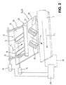
- Fig. 2 is a schematic perspective representation of an intermediate conveying device and an oblique conveying device of the transfer device of an enclosure-collating device according to Fig. 1.
- Fig. 3 is a schematic perspective representation of another embodiment of the intermediate conveying device and the oblique conveying device of the transfer device for an enclosure-collating device according to Fig. 1.
- Fig. 1 shows in a perspective, highly schematicized representation, a detail of an enclosure-collating device of the type being suggested here. It contains an enclosure-conveying arrangement 1 with endless, according to the present embodiment, continuously driven, circulating conveying chains or conveying belts 2, 3 that are provided with conveying fingers 4, 5.
- the conveying chains or conveying belts are guided by chain wheels or pulleys at the beginning and end of the enclosure-conveying arrangement, as is shown only schematically in Fig. 1, whereby a chain-wheel pair or a pulley pair is coupled with a suitable driving means.
- the conveying fingers 4, 5 project above the surface 6 of a collating path 7 and, in pairs, define enclosure-conveying compartments 8 and 9 that are located in front of them as seen in the conveying direction.
- Enclosure-conveying segments or compartments of the functional type of the compartments 8 and 9 can also be defined without the use of conveying fingers.
- each of the transfer devices 12 contains an intermediate conveying device 13 by means of which individual enclosures from a supply of enclosures or from a stream of separate enclosures are conveyed in the direction of the enclosure-conveying arrangement essentially perpendicularly to the conveying direction of the latter.
- the intermediate conveying devices 13 are in the form of endless conveyor belts or conveying belts 15, which are put into circulation by driving means 14 and the top strands of which project through cutouts slightly above the surface of transfer tables 16 and which have the task of frictionally connecting these top strands from underneath to enclosures that have been applied through an unshown means and moving such enclosures forward in the direction perpendicular to the conveying direction of the enclosure-conveying arrangement.
- pressing means that are familiar to the person skilled in the art can be provided in the region of the transfer devices 12, although they are not shown in the drawing.
- Such pressing means have, for example, the form of brush strips or of plates mounted at a suitable distance above the transfer tables 16, or else of rolling balls held and supported in cages or cage arrangements that lie with limited pressing force on the fed enclosures.
- the relevant enclosure is brought to a standstill on its conveying path perpendicular to the conveying direction of the enclosure-conveying arrangement by a stopping means, not shown in Fig. 1, and is only released for further conveying when an enclosure-conveying compartment 8, 9 that is able to receive it moves past the relevant enclosure-feeding device 10, 11.
- an oblique conveying device 19 and 20 of the transfer device 10 and 11 grips a particular enclosure lying on the transfer table 16 and conveys this enclosure from the conveying end position of the intermediate conveying device 13 in a translatory, essentially linear movement at an angle ⁇ to the conveying direction of the envelope-conveying device 1 obliquely into the associated enclosure compartment 8 and 9, whereby as a result, the trailing edge, as seen in the conveying direction of the enclosure-conveying arrangement, of the obliquely conveyed enclosure moves away in front of the rear delimitations 17, 18 of the enclosure-conveying compartments as a result of the translatory, oblique conveying until the oblique conveying devices 19, 20 have released the particular enclosure and a side edge of the relevant enclosure has pushed against a guide flange or guide straightedge 21 of the collating path 1.
- the oblique conveying of enclosures into the enclosure compartments 8, 9 in an essentially linear movement as described and explained with the aid of Fig. 1 has the advantage over a translatory circular movement that adjusting the coordinated control of the particular conveying driving means and the adjusting of the conveying phases to the formats of the enclosures to be inserted and to the particular drive speeds are simple and concise.
- the oblique conveying devices 19, 20 perform an oblique conveying of the enclosures delivered by the intermediate conveying devices 13 linearly at a speed such that after the obliquely conveyed enclosures come free of the oblique conveying devices 19, 20, the enclosures are moved ahead up to the stop flange or the stop straightedge 21 [sic] while finally completely filling the enclosure-conveying compartments 8 and 9, so that in the embodiment shown in Fig. 1, the oblique conveying devices 19, 20 are always located completely outside the conveying route of the enclosures along the enclosure-conveying arrangement 1.
- the oblique conveying devices 19, 20 can then involve obliquely conveying friction roller sets that act only above the enclosure surfaces, or circulating belts that are provided with vacuum openings and do not require a support mechanism below the level of the transfer tables 16 or the collating path of the enclosure-conveying arrangement.
- a control unit is provided which is not shown in Fig. 1, but which controls a driving means of the oblique conveying devices 19, 20 in dependence on the drive speed of a driving means of the enclosure-conveying arrangement 1 in such a way that the vector of the speed of an enclosure as a result of being driven by the oblique conveying devices 19, 20 has a component in the direction of the collating path that is essentially equal to the vector of the drive speed of the conveying fingers 4, 5.
- the magnitude of the drive speed of the conveying fingers 4, 5 is equal to V
- the magnitude of the drive speed of the oblique conveying devices 19, 20 is V/cos ⁇ , as is made clear in Fig. 1 by the corresponding arrows.
- the feeding of enclosures into the enclosure-conveying compartments 8, 9 during their continuous movement past the transfer devices 10, 11 has the significant advantage of good accessibility to the collating path to clear malfunctions.
- Fig. 2 shows in schematic and perspective representation an embodiment of an intermediate conveying device and an oblique conveying device for a transfer device 10, 11. Parts corresponding to those of the embodiment according to Fig. 1 have been provided with the same reference symbols in Fig. 2.
- the intermediate conveying device 13 has the form of conveyor belts or conveying belts 15 which are guided parallel to one another, with the top strands reaching above cutouts in a transfer table 16, and which are put into circulation by a driving means 14 and which convey by means of frictional forces enclosures from, for example, a supply of enclosures or from a stream of separate enclosures that are placed on the transfer table 16, in the direction towards a stopping straightedge 23.
- a driving means 14 convey by means of frictional forces enclosures from, for example, a supply of enclosures or from a stream of separate enclosures that are placed on the transfer table 16, in the direction towards a stopping straightedge 23.
- a driving means for the vacuum conveyor belts 26, 27, which is designated 28, the driving means 14 that moves the conveyor belts or conveying belts 15, and the driving means 24 for pivoting the stopping straightedge 23 up and down, are connected to a control unit 29, which also receives detector signals from the collating path 7, which is indicated by the dot-dash line at 30, whereby the detector signals report the particular operating positions of the conveying fingers 4, 5 to the control unit 29.
- the conveyor belts or conveying belts 15 and the vacuum conveyor belts 26, 27 can also be driven intermittently in a suitable chronological overlapping and matched to a work cycle of the stopping straightedge 23.
- the embodiment of the transfer device 12 according to Fig. 3 differs from the one according to Fig. 2 primarily in that here the use of a stopping straightedge 23 to stop an enclosure in the region of the intermediate conveying device for further conveying by the oblique conveying device 19, 20 is dispensed with.
- the oblique conveying devices 19, 20 have the form of roller pairs 32 and 33 plus 34 and 35, whereby each of the lower rollers 33 and 35 is placed under the transfer table 16 and projects above the level of the transfer table through cutouts in the transfer table in the flat regions at the end of the conveyor belts or conveying belts 15 of the intermediate conveying device.
- the lower rollers 33 and 35 are driven synchronously intermittently by a driving means 28.
- the spring-loaded upper rollers 32 and 34, which are prestressed against the lower rollers 33 and 35 by prestressing means, not shown, are track rollers.
- rollers 32 to 35 possess drive shafts or bearing spindles having an orientation relative to the drive shafts or bearing spindles of the rollers for the conveyor belts or conveying belts 15 is (90° + ⁇ ), so that the conveying direction according to arrow P2 in turn takes on an angle ⁇ with respect to the conveying direction of the collating path according to arrow P3.
- enclosures from a supply of enclosures or from a stream of separate enclosures are placed on the transfer table 16 and are conveyed by the intermediate conveying device's conveyor belts or conveying belts 15, which are kept in continuous circulation while maintaining friction tightness, which allows movement of an enclosure with a movement component transverse to the conveying direction of the intermediate conveying device according to arrow P1, against the roller pairs 32 and 33 plus 34 and 35, which at first are still not driven and are standing still, and which form with the conveying nip between them a stop for the enclosures conveyed by the conveyor belts or conveying belts 15, by means of which the leading edge, as seen from the conveying direction according to arrow P1, of an enclosure is aligned parallel to the conveying direction according to arrow P3 of the collating path, or remains aligned if an aligned conveying has already taken place.
- a control unit 29 by means of which the switching on and switching off of the driving means 28 is controlled, for example, in dependence on position report signals from the line 30 in accordance with the particular instantaneous position of the enclosure-conveying compartments.
- An intermittent switching on of the driving means 14 for the conveyor belts or conveying belts 15 of the intermediate conveying device can also be carried out by the control unit 29 in accordance with a modified operational mode.
- the intermediate conveying device can also be equipped with vacuum conveyor belts similar to the conveyor belts 26 and 27 of the embodiment according to Fig. 2 instead of the conveyor belts or conveying belts 15 that grasp the enclosure undersides frictionally.
- the oblique conveying device can accept enclosures from the intermediate conveying device and with a movement component transverse to the conveying direction of the intermediate conveying device, can remove them from same in a translatory, essentially linear movement.
Landscapes
- Delivering By Means Of Belts And Rollers (AREA)
- Collation Of Sheets And Webs (AREA)
- Attitude Control For Articles On Conveyors (AREA)
Applications Claiming Priority (2)
| Application Number | Priority Date | Filing Date | Title |
|---|---|---|---|
| DE10340220 | 2003-09-01 | ||
| DE10340220A DE10340220A1 (de) | 2003-09-01 | 2003-09-01 | Beilagen-Zusammentrageinrichtung, insbesondere für Postbearbeitungsanlagen |
Publications (3)
| Publication Number | Publication Date |
|---|---|
| EP1524128A2 true EP1524128A2 (de) | 2005-04-20 |
| EP1524128A3 EP1524128A3 (de) | 2005-05-11 |
| EP1524128B1 EP1524128B1 (de) | 2010-10-06 |
Family
ID=34258312
Family Applications (1)
| Application Number | Title | Priority Date | Filing Date |
|---|---|---|---|
| EP04020627A Expired - Lifetime EP1524128B1 (de) | 2003-09-01 | 2004-08-31 | Kuvertier- und Zusammenstellungsvorrichtung, insbesondere für Postverarbeitungsanlagen |
Country Status (4)
| Country | Link |
|---|---|
| US (1) | US7213808B2 (de) |
| EP (1) | EP1524128B1 (de) |
| CA (1) | CA2480040C (de) |
| DE (1) | DE10340220A1 (de) |
Cited By (1)
| Publication number | Priority date | Publication date | Assignee | Title |
|---|---|---|---|---|
| IT201700106547A1 (it) * | 2017-09-22 | 2019-03-22 | Sitma Machinery S P A | Modulo di alimentazione per l’alimentazione di inserti in foglio ad un trasportatore principale a spintori di una macchina per la lavorazione di prodotti in foglio. |
Families Citing this family (6)
| Publication number | Priority date | Publication date | Assignee | Title |
|---|---|---|---|---|
| JP4403923B2 (ja) * | 2004-08-26 | 2010-01-27 | コニカミノルタビジネステクノロジーズ株式会社 | 用紙搬送装置、用紙後処理装置及び画像形成装置 |
| US7530566B2 (en) * | 2007-04-02 | 2009-05-12 | Toshiba Tec Kabushiki Kaisha | Sheet post-processing apparatus |
| US7775015B1 (en) | 2007-09-04 | 2010-08-17 | Crowley H W | System and method for high-speed insertion of envelopes |
| US9452635B2 (en) * | 2013-11-13 | 2016-09-27 | T.S.D. Llc | Apparatus for inserting documents into envelopes and associated method |
| CN104709743B (zh) * | 2013-12-16 | 2018-02-23 | 上海旭恒精工机械制造有限公司 | 片状物传输系统 |
| CN115402685B (zh) * | 2022-09-15 | 2025-08-05 | 苏州芯鸿海智能科技有限公司 | 一种仓储结构 |
Family Cites Families (11)
| Publication number | Priority date | Publication date | Assignee | Title |
|---|---|---|---|---|
| US4257587A (en) * | 1978-10-30 | 1981-03-24 | Xerox Corporation | Document registering and feeding apparatus |
| WO1994013566A1 (de) * | 1992-12-04 | 1994-06-23 | Grapha-Holding Ag | Einrichtung zum hüberführen eines aus druckprodukten gebildeten schuppenstroms |
| US5413326A (en) * | 1993-12-27 | 1995-05-09 | Pitney Bowes Inc. | Apparatus for changing the direction of motion of documents |
| US5775690A (en) * | 1996-04-01 | 1998-07-07 | Xerox Corporation | Two step optimized stalled roll registration and deskew |
| JP3662385B2 (ja) * | 1997-04-18 | 2005-06-22 | オムロン株式会社 | 用紙搬送装置 |
| US6168154B1 (en) * | 1997-05-26 | 2001-01-02 | Nisca Corporation Yamanashi-Ken | Sheet handling device for continually fed sheets which are aligned and moved from first to second storage locations |
| DE19819736C1 (de) * | 1998-05-02 | 1999-09-02 | Boewe Systec Ag | Vorrichtung zum Übereinanderlegen von Papierblättern oder dgl. |
| DE19935186C1 (de) | 1999-07-27 | 2000-11-02 | Boewe Systec Ag | Verfahren und Vorrichtung zum geschuppten Anordnen von zumindest zwei Blättern |
| IT1317704B1 (it) | 2000-05-29 | 2003-07-15 | Sitma Spa | Procedimento di alimentazione di prodotti in foglio ad untrasportatore e gruppo di prelievo. |
| EP1231176B1 (de) * | 2001-02-08 | 2004-09-01 | Grapha-Holding AG | Vorrichtung zum Zuführen von Druckprodukten in einen Förderkanal |
| DE10220908C1 (de) | 2002-05-10 | 2003-06-18 | Pitney Bowes Technologies Gmbh | Kuvertierstation für Postbearbeitungssysteme |
-
2003
- 2003-09-01 DE DE10340220A patent/DE10340220A1/de not_active Withdrawn
-
2004
- 2004-08-25 US US10/925,403 patent/US7213808B2/en not_active Expired - Lifetime
- 2004-08-27 CA CA002480040A patent/CA2480040C/en not_active Expired - Fee Related
- 2004-08-31 EP EP04020627A patent/EP1524128B1/de not_active Expired - Lifetime
Cited By (1)
| Publication number | Priority date | Publication date | Assignee | Title |
|---|---|---|---|---|
| IT201700106547A1 (it) * | 2017-09-22 | 2019-03-22 | Sitma Machinery S P A | Modulo di alimentazione per l’alimentazione di inserti in foglio ad un trasportatore principale a spintori di una macchina per la lavorazione di prodotti in foglio. |
Also Published As
| Publication number | Publication date |
|---|---|
| CA2480040C (en) | 2007-11-20 |
| CA2480040A1 (en) | 2005-03-01 |
| EP1524128A3 (de) | 2005-05-11 |
| US7213808B2 (en) | 2007-05-08 |
| DE10340220A1 (de) | 2005-04-07 |
| US20050072126A1 (en) | 2005-04-07 |
| EP1524128B1 (de) | 2010-10-06 |
Similar Documents
| Publication | Publication Date | Title |
|---|---|---|
| US4230218A (en) | Apparatus for transporting layers of sheets | |
| FI106709B (fi) | Menetelmä ja laite painotuotteiden käsittelemiseksi | |
| FI61288C (fi) | Anordning foer utjaemning av en oeverlappningsstroem av tryckalster | |
| CA2740834C (en) | Conveying apparatus for envelopes and related methods | |
| JPS59212353A (ja) | 刷り紙からなる印刷部片の流れを区分印刷部片に区分する区分装置 | |
| US5249788A (en) | Sheet stack pre-feeder | |
| US20090072474A1 (en) | Conveyor-technology device | |
| US4227685A (en) | Sheet feeding apparatus, particularly for rotary printing machines | |
| CA2480040C (en) | Enclosure-collating device, in particular for mail-processing installations | |
| US5056773A (en) | Sheet deliverer | |
| US3605980A (en) | Turning conveyor | |
| EP1502889A2 (de) | Dokumentstapeleinheit | |
| JPH0739297B2 (ja) | 可撓性の扁平な製品、特に印刷物をその処理装置に装入する装置 | |
| JP2001354348A (ja) | 物品を供給するための装置および方法 | |
| WO1995017984A1 (en) | Gripper feeder for metal strip | |
| US6959526B2 (en) | Inserter station for mail processing systems | |
| US6619650B2 (en) | Device for feeding printed products to a conveying channel | |
| EP1524129A2 (de) | Kuvertierstation für Postverarbeitungssysteme | |
| US5443256A (en) | Process and device for the formation of a scale-like stream of folded printed copies | |
| CN1689835B (zh) | 用于转送书心子或书本以便流水作业地加工的设备 | |
| JP4169872B2 (ja) | 用紙搬送装置 | |
| US6461102B2 (en) | Charging apparatus | |
| KR20090028837A (ko) | 다이 절단 프레스의 공급 테이블상의 시트를 이송하는 보조구동 장치 | |
| EP0825118A1 (de) | Verfahren zum Bilden von Gruppen von Paketen | |
| DE59202505D1 (de) | Bogenfördereinrichtung in Aus- bzw. Anlegern von Druckmaschinen. |
Legal Events
| Date | Code | Title | Description |
|---|---|---|---|
| PUAI | Public reference made under article 153(3) epc to a published international application that has entered the european phase |
Free format text: ORIGINAL CODE: 0009012 |
|
| PUAL | Search report despatched |
Free format text: ORIGINAL CODE: 0009013 |
|
| AK | Designated contracting states |
Kind code of ref document: A2 Designated state(s): AT BE BG CH CY CZ DE DK EE ES FI FR GB GR HU IE IT LI LU MC NL PL PT RO SE SI SK TR |
|
| AX | Request for extension of the european patent |
Extension state: AL HR LT LV MK |
|
| AK | Designated contracting states |
Kind code of ref document: A3 Designated state(s): AT BE BG CH CY CZ DE DK EE ES FI FR GB GR HU IE IT LI LU MC NL PL PT RO SE SI SK TR |
|
| AX | Request for extension of the european patent |
Extension state: AL HR LT LV MK |
|
| 17P | Request for examination filed |
Effective date: 20051025 |
|
| AKX | Designation fees paid |
Designated state(s): FR GB |
|
| REG | Reference to a national code |
Ref country code: DE Ref legal event code: 8566 |
|
| 17Q | First examination report despatched |
Effective date: 20071126 |
|
| GRAJ | Information related to disapproval of communication of intention to grant by the applicant or resumption of examination proceedings by the epo deleted |
Free format text: ORIGINAL CODE: EPIDOSDIGR1 |
|
| GRAP | Despatch of communication of intention to grant a patent |
Free format text: ORIGINAL CODE: EPIDOSNIGR1 |
|
| GRAS | Grant fee paid |
Free format text: ORIGINAL CODE: EPIDOSNIGR3 |
|
| GRAA | (expected) grant |
Free format text: ORIGINAL CODE: 0009210 |
|
| AK | Designated contracting states |
Kind code of ref document: B1 Designated state(s): FR GB |
|
| REG | Reference to a national code |
Ref country code: GB Ref legal event code: FG4D |
|
| PLBE | No opposition filed within time limit |
Free format text: ORIGINAL CODE: 0009261 |
|
| STAA | Information on the status of an ep patent application or granted ep patent |
Free format text: STATUS: NO OPPOSITION FILED WITHIN TIME LIMIT |
|
| 26N | No opposition filed |
Effective date: 20110707 |
|
| GBPC | Gb: european patent ceased through non-payment of renewal fee |
Effective date: 20110831 |
|
| REG | Reference to a national code |
Ref country code: FR Ref legal event code: ST Effective date: 20120430 |
|
| PG25 | Lapsed in a contracting state [announced via postgrant information from national office to epo] |
Ref country code: GB Free format text: LAPSE BECAUSE OF NON-PAYMENT OF DUE FEES Effective date: 20110831 Ref country code: FR Free format text: LAPSE BECAUSE OF NON-PAYMENT OF DUE FEES Effective date: 20110831 |