EP1524430A2 - Démarreur-générateur muni d'une roue libre auto-inverseuse - Google Patents
Démarreur-générateur muni d'une roue libre auto-inverseuse Download PDFInfo
- Publication number
- EP1524430A2 EP1524430A2 EP04022895A EP04022895A EP1524430A2 EP 1524430 A2 EP1524430 A2 EP 1524430A2 EP 04022895 A EP04022895 A EP 04022895A EP 04022895 A EP04022895 A EP 04022895A EP 1524430 A2 EP1524430 A2 EP 1524430A2
- Authority
- EP
- European Patent Office
- Prior art keywords
- pulley
- hub
- shaft
- freewheel
- spring
- Prior art date
- Legal status (The legal status is an assumption and is not a legal conclusion. Google has not performed a legal analysis and makes no representation as to the accuracy of the status listed.)
- Granted
Links
Images


Classifications
-
- F—MECHANICAL ENGINEERING; LIGHTING; HEATING; WEAPONS; BLASTING
- F02—COMBUSTION ENGINES; HOT-GAS OR COMBUSTION-PRODUCT ENGINE PLANTS
- F02N—STARTING OF COMBUSTION ENGINES; STARTING AIDS FOR SUCH ENGINES, NOT OTHERWISE PROVIDED FOR
- F02N15/00—Other power-operated starting apparatus; Component parts, details, or accessories, not provided for in, or of interest apart from groups F02N5/00 - F02N13/00
- F02N15/02—Gearing between starting-engines and started engines; Engagement or disengagement thereof
- F02N15/022—Gearing between starting-engines and started engines; Engagement or disengagement thereof the starter comprising an intermediate clutch
- F02N15/023—Gearing between starting-engines and started engines; Engagement or disengagement thereof the starter comprising an intermediate clutch of the overrunning type
-
- F—MECHANICAL ENGINEERING; LIGHTING; HEATING; WEAPONS; BLASTING
- F02—COMBUSTION ENGINES; HOT-GAS OR COMBUSTION-PRODUCT ENGINE PLANTS
- F02N—STARTING OF COMBUSTION ENGINES; STARTING AIDS FOR SUCH ENGINES, NOT OTHERWISE PROVIDED FOR
- F02N15/00—Other power-operated starting apparatus; Component parts, details, or accessories, not provided for in, or of interest apart from groups F02N5/00 - F02N13/00
- F02N15/02—Gearing between starting-engines and started engines; Engagement or disengagement thereof
-
- F—MECHANICAL ENGINEERING; LIGHTING; HEATING; WEAPONS; BLASTING
- F02—COMBUSTION ENGINES; HOT-GAS OR COMBUSTION-PRODUCT ENGINE PLANTS
- F02N—STARTING OF COMBUSTION ENGINES; STARTING AIDS FOR SUCH ENGINES, NOT OTHERWISE PROVIDED FOR
- F02N11/00—Starting of engines by means of electric motors
- F02N11/04—Starting of engines by means of electric motors the motors being associated with current generators
Definitions
- the invention relates to a starter generator with pulley, within the pulley arranged shaft and a freewheel, the loaded by a spring device clamping body, with the features mentioned in the preamble of claim 1 as well a pulley with the mentioned in the preamble of claim 8 Features.
- Belt driven starter generators for internal combustion engines of generic type are known. They are a favored variant for a low-closing starter system, which is used in vehicles with Start-stop automatic is used, since by the occurring Ten times the number of starts of conventional single-track starters can not be used anymore.
- WO 01/77520 A1 and WO 01/88369 A1 are devices for coupling a belt-driven Starter generator with an internal combustion engine disclosed. These have a planetary gear with a sun gear on, wherein the torque reversal switch active by Coupling elements takes place.
- Pulleys with freewheel shortly belt freewheel disks also described in the prior art. They have a freewheel ring and clamping body with a spring device. This in the State of the art described pulleys with freewheel can but not used for the belt-driven starter generator come when using the belt-driven starter generator in starter mode, ie as a motor for starting an internal combustion engine, the torque in the opposite direction to the Torque in generator mode, ie when the internal combustion engine is running, occurs.
- the starter generator according to the invention with the mentioned in claim 1 offers the advantage over that in generator mode the function of the known freewheel pulley is met and opposite torques in starter operation be transmitted. This is through the use of a double freewheel achieved in the belt-driven starter generator.
- the double freewheel has pairs of mutually associated clamp body, between where the spring device is arranged.
- the clamp body interact with different clamping gaps. It is one provided the hub surrounding the shaft, being between hub and Shaft provided a spring coupling with at least two springs is.
- the clamping body between hub and pulley are with a control cage coupled to the pulley.
- the coupling of the control cage with the pulley is effected by means of friction elements.
- the advantage of a coupling by means of friction elements is that that the coupling is not rigid, but is operatively connected. She is on the other side so rigid that during a movement of the pulley the control cage the same movement as the pulley performs. When the direction of the pulley turns, thus also rotates the direction of movement of the control cage around.
- the springs of the spring coupling between Shaft and hub have different stiffnesses. Thereby an angle range is preceded, the only small Can transmit torques. As a result, a "loose”, wherein the "lots” has a larger angle than a difference angle between pulley and shaft. This difference angle arises in particular at the start of the engine and results from the non-uniform rotational speed of Internal combustion engine and out of that, under its inertial mass uniform rotating, starter generator. This nonuniformity is only quite large at the beginning of the boot process decreases with increasing speed of the internal combustion engine.
- the springs are designed as coil springs.
- damping rooms available be filled with at least one medium.
- These muffling rooms form between the driver of the wave and the Inner contour of the hub. They act like throttles.
- a medium can have gases with different compressibility properties or liquids with different viscosities used become.
- the clearance angle of the Federkopplung be set, namely by series connection of at least two hubs with drivers and associated Feathers.
- the geometric series connection of the hubs with drivers and associated springs can both on the axle the shaft one behind the other, so axially, take place, as well as coaxially.
- Coaxial here means annularly arranged around the shaft scars.
- the inner hub represents the shaft for the next Hub, making multiple hub and shaft pairs in between arranged springs are realized. It is possible the clearance angle by using different springs with different ones To increase stiffness
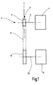
- Figure 1 shows an arrangement of a starter generator 1 with a Shaft 3, which has a shaft axis 4 and with the starter generator 1 is connected.
- the shaft 3 is part of a device 5, from the only one pulley 7 is shown in this figure.
- the pulley 7 is by means of a belt 9 with a pulley eleventh an internal combustion engine 15 is connected.
- the pulley 11 is connected by a shaft 13 to the engine 15.
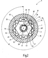
- FIG. 2 shows the starter generator 1 according to the invention with the device 5 along the line I-I of the arrangement shown in Figure 1 shown. Identical parts are designated by the same reference numerals. It Reference is made to the description of Figure 1 to repetitions to avoid.
- the device 5 has the pulley 7, the shaft 3 of the starter generator 1 and one between the shaft 3 and the pulley 7 arranged hub 19.
- the shaft 3 has an outer Circumference 21 a driver 23, which integral with the Wave 3 is connected.
- the driver 23 has a nearly rectangular Base surface 25, the almost vertical side surfaces 26th and 26 '. In the figure, only the rectangular base 25 shown. A geometric dimension of the driver 23 in FIG Direction of the shaft axis 4 can not be seen in the sectional view.
- the hub 19 has an inner contour 29. On the inner contour 29 is integrally formed with the hub 19, a driver 31. Of the driver 31 is also a base 33 in the Figure shown.
- the base 33 of the hub 19 has a nearly perpendicular to the inner contour 29 of the hub 19 aligned side surfaces 35 and an almost parallel to this side surface 35 'on.
- a spring 37 is arranged between the side surface 35 'of the driver 31 and the side surface 26 of the driver 23 .
- a spring 39 is arranged between the side surface 26 'of the driver 23 and the side surface 35 of the Driver 33 .
- the springs 37 and 39 have different stiffnesses. Rotates the shaft 3 dextrorotatory, the spring 39 is compressed, the turns Shaft 3 counterclockwise, the spring 37 is compressed. rotates However, when the hub 19 clockwise, the spring 37 is compressed and when the hub 19 is moved counterclockwise the spring 39 compressed.
- the shaft 3 and the hub 19 are So according to the springways 37 and 39 relative to each other rotatable. It can from the hub 19 to the shaft 3 torques be transferred and vice versa.
- Stiffnesses of the springs 37 and 39 is the one for transmission the same torques necessary twist angle different large.
- the distance between the driver 23 and driver 31, the is adjustable by the springs 37 and 39, is referred to as clearance angle 41.
- the hub 19 has an outer contour 43. Between the outer contour 43 of the hub 19 and the pulley 7 is a double freewheel 47 arranged.
- the double freewheel 47 has at least two Clamping elements 49 and 51 and a between two clamping elements 49 and 51 arranged spring means 53 and a control cage 55.
- the double freewheel six of the at least two clamping elements 49 and 51, So a total of twelve, each pairwise cooperating, Clamping elements.
- the control cage 55 is not shown here Friction elements with the pulley 7 operatively connected, so that a Torque is transmitted. This means that when turning the Pulley 7 in a direction of the control cage 55 in the same Direction is turned.
- the control cage 55th is provided by means of friction elements Coupling with the pulley 7 prevented by the Hub 19 to be turned.
- the clamping elements 49 and 51 of Double Freewheel 47 can be used in different versions be, for example, as a roller clamp or balls.
- hubs and shafts with springs in a row can be axles and hubs connected axially one behind the other exhibit. It is also conceivable hubs and shafts coaxial, so onion-shaped, to switch one behind the other, with an internal one Hub serves as a shaft for the external hub.
- Rooms are formed, which are preferably filled with media, the more or less compressible, and so to an additional Damping of bumps and noises.
- the springs are replaced by spaces that are filled with media be, so that the adjustment of the clearance angle by, for example two rooms filled with different compressible gases he follows.
- different sized throttles be formed through the rooms. Under media can be liquids or gases are understood. Generally speaking Liquids absorb opposing forces and thus a damping of Effect relative movement. The damping can be adjusted through the choice of the medium and the fact that the rooms with more or less large throttles interact by the respective Medium flows in and out.
- the clearance angle 41 is formed. It is, as already described, also possible to switch hubs and shafts one behind the other, so that the resulting clearance angle is the sum of the single clearance angle between each pair, consisting of a hub and a shaft, composed.
- the device 5 is shown in starter mode.
- a through the shaft 3 introduced right-handed torque, which is symbolized by the arrow 59, via the soft spring 39, which is shown here in block pressed state, from the driver 23 of the shaft 3 via the driver 31 of the hub 19 finally on the hub 19 transferred.
- the spring 39 as a soft spring, that is with low spring stiffness, be formed even at small Torques large shaft rotation angle and thus large difference angle generated to the hub 19.
- the hub 19 begins to turn and
- a clamping gap 63 is released and the clamping body 49 transmits the clockwise torque, shown as arrow 59, from the hub 19 to the pulley 7.
- the clamp body 51 now form a self-lifting Freewheel. That is, the clamping body 51, by the centrifugal force the inner wall of the pulley 7 are pressed, run with the Pulley 7 as a rigid body, do not transmit moments and perform no relative movement to the pulley 7. rotates due to the nonuniformity of the internal combustion engine 15th the torque direction is around, so is due to the with clamping body 49 closed freewheel, the hub 19 accelerated by the spring 39. A reversal of the clockwise torque, the is transmitted via the spring 39 to the hub 19, takes place only when the spring travel of the spring 39 is fully utilized. If the two Mit vide 31 and 23 on the spring 37 collide, opens the over the clamping body 49 formed freewheel 41.
- the clearance angle 41 between the driver 23 and the driver 31 is selected be that before closing the clamp body 51 of the Torque input caused by the reversal of the direction of torque was caused, must be finished. Is particularly advantageous it, if one of the spring 39 and the clearance angle 41 compensatable angular difference, which is greater than / equal to the largest Differential angle during startup is.
- the clearance angle 41 and thus the compensatable angular difference can be enlarged by hubs with drivers and springs in a row be switched.
- Under series connection can both an axial series of hubs and shafts be understood, as well as a coaxial series connection analogous to a onion-like structure.
- In the coaxial series connection of hubs and shafts each acts the outside a hub as a shaft for the next overlying hub.
- the device 5 is in generator operation, that is, while it is running Internal combustion engine 15 shown.
- a right-handed torque shown as arrow 65
- the pulley moves 7th dextrorotatory and drags by means of the friction elements, not shown the control cage 55 clockwise with.
- This will be Clamping column 61 released for the clamping elements 51.
- the clamping elements 51 are moved by the springs 53 in clamping gaps 61 and thus transmit the dextrorotatory torques 65 from the Pulley 7 on the hub 19.
- the driver 31 transmits the spring 37 the right-handed torque on the driver 23 on the shaft 3.
- the clamping body 49 are through the control cage 55 prevented from falling into the nip 63 and become pressed by the centrifugal force to the outside, so they with the pulley 7 rotate as a rigid body, so no torque transfer. They form such a low-wear self-lifting Freewheel.
- the between Pulley 7 and pulley 11 is the belt tension in the area of the belt 9 between the pulley 7 of the starter generator 1 and the pulley 11 of Internal combustion engine 15 is to put under load.
- the Pulley 7 of the starter generator 1 counterclockwise turned in the left direction. Since the pulley 11 of Internal combustion engine 15 is at rest, the belt 9 spans between Pulley 7 of the starter generator 1 and pulley 11 of the internal combustion engine 15.
- the in Figure 4 described ratios for the clamping body 49 and 51 on.
- the shaft 3 rotates counterclockwise and the Driver 23 is moved to the driver 31 of the hub 19 out and thus transmits the left-handed torque 69 to the hub 19.
- the clamping body 51 is moved to the clamping body 49 to.
- the springs 53 Press the clamp body 49 lying in front of the springs 53 in the Clamping column 63 and thus transmit the torque 69 of the Hub 19 on the pulley 7.
- the pulley 7 is thus rotated and tensioned the belt 9 between the pulley 7 of the Starter generator 1 and pulley 11 of the internal combustion engine 15 against the negative drag torque of the internal combustion engine 15, since the pulley 11 is at rest.
Landscapes
- Engineering & Computer Science (AREA)
- Chemical & Material Sciences (AREA)
- Combustion & Propulsion (AREA)
- Mechanical Engineering (AREA)
- General Engineering & Computer Science (AREA)
- Devices For Conveying Motion By Means Of Endless Flexible Members (AREA)
- Connection Of Motors, Electrical Generators, Mechanical Devices, And The Like (AREA)
Applications Claiming Priority (2)
| Application Number | Priority Date | Filing Date | Title |
|---|---|---|---|
| DE2003147422 DE10347422A1 (de) | 2003-10-13 | 2003-10-13 | Startergenerator mit selbsttätig umschaltendem Freilauf |
| DE10347422 | 2003-10-13 |
Publications (3)
| Publication Number | Publication Date |
|---|---|
| EP1524430A2 true EP1524430A2 (fr) | 2005-04-20 |
| EP1524430A3 EP1524430A3 (fr) | 2006-10-25 |
| EP1524430B1 EP1524430B1 (fr) | 2009-12-02 |
Family
ID=34353374
Family Applications (1)
| Application Number | Title | Priority Date | Filing Date |
|---|---|---|---|
| EP20040022895 Expired - Lifetime EP1524430B1 (fr) | 2003-10-13 | 2004-09-25 | Démarreur-générateur muni d'une roue libre auto-inverseuse |
Country Status (2)
| Country | Link |
|---|---|
| EP (1) | EP1524430B1 (fr) |
| DE (2) | DE10347422A1 (fr) |
Cited By (2)
| Publication number | Priority date | Publication date | Assignee | Title |
|---|---|---|---|---|
| DE102009035178A1 (de) | 2009-07-29 | 2011-02-10 | Daimler Ag | Freilauf für einen Starter einer Verbrennungskraftmaschine sowie Verbrennungskraftmaschine |
| EP2673496B1 (fr) * | 2011-02-09 | 2020-12-30 | Schaeffler Technologies AG & Co. KG | Procédé et dispositif pour le démarrage d'un moteur à combustion interne |
Families Citing this family (2)
| Publication number | Priority date | Publication date | Assignee | Title |
|---|---|---|---|---|
| DE102009034339A1 (de) * | 2009-07-23 | 2011-01-27 | Bayerische Motoren Werke Aktiengesellschaft | Nebenaggregateantrieb |
| DE102010000999B4 (de) * | 2010-01-19 | 2018-03-01 | Siemens Aktiengesellschaft | Dynamoelektrische Maschine mit Läuferblockiereinrichtung |
Family Cites Families (6)
| Publication number | Priority date | Publication date | Assignee | Title |
|---|---|---|---|---|
| FR609501A (fr) * | 1926-01-18 | 1926-08-16 | Perfectionnements aux accouplements élastiques | |
| DE635474C (de) * | 1932-12-13 | 1936-09-18 | Zahnradfabrik Friedrichshafen | Kupplungsvorrichtung, insbesondere fuer Kraftfahrzeuge, mit in der Vorwaerts-bzw. Rueckwaertstriebrichtung benuetzbaren Klemmkoerpern |
| US2209459A (en) * | 1938-03-03 | 1940-07-30 | Gen Motors Corp | Overrunning clutch |
| DE19919449B4 (de) * | 1998-05-04 | 2015-10-15 | Schaeffler Technologies AG & Co. KG | Triebscheibe |
| DE19852085C1 (de) * | 1998-11-12 | 2000-02-17 | Daimler Chrysler Ag | Starteinrichtung für eine Brennkraftmaschine und Verfahren zum Starten der Brennkraftmaschine |
| DE10253495A1 (de) * | 2001-12-14 | 2003-09-11 | Ina Schaeffler Kg | Generatorfreilauf für einen riemengetriebenen Startergenerator |
-
2003
- 2003-10-13 DE DE2003147422 patent/DE10347422A1/de not_active Ceased
-
2004
- 2004-09-25 DE DE200450010439 patent/DE502004010439D1/de not_active Expired - Lifetime
- 2004-09-25 EP EP20040022895 patent/EP1524430B1/fr not_active Expired - Lifetime
Cited By (2)
| Publication number | Priority date | Publication date | Assignee | Title |
|---|---|---|---|---|
| DE102009035178A1 (de) | 2009-07-29 | 2011-02-10 | Daimler Ag | Freilauf für einen Starter einer Verbrennungskraftmaschine sowie Verbrennungskraftmaschine |
| EP2673496B1 (fr) * | 2011-02-09 | 2020-12-30 | Schaeffler Technologies AG & Co. KG | Procédé et dispositif pour le démarrage d'un moteur à combustion interne |
Also Published As
| Publication number | Publication date |
|---|---|
| EP1524430A3 (fr) | 2006-10-25 |
| DE10347422A1 (de) | 2005-06-02 |
| EP1524430B1 (fr) | 2009-12-02 |
| DE502004010439D1 (de) | 2010-01-14 |
Similar Documents
| Publication | Publication Date | Title |
|---|---|---|
| DE10059101B4 (de) | Antriebssystem | |
| DE4425710B4 (de) | Stufenlos variierbares Getriebe vom Reibungstyp | |
| DE3703123C2 (de) | Dämpfungseinrichtung | |
| EP2012044B1 (fr) | Amortisseur mécanique de vibrations de torsion | |
| WO2008071306A1 (fr) | Ensemble découpleur | |
| DE19525842C2 (de) | Torsionsschwingungsdämpfer mit variabler Übersetzung | |
| DE102009013996A1 (de) | Einrichtung zur Verstellung der Exzentrizität für ein Kurbel-CVT-Getriebe | |
| DE102013201619A1 (de) | Drehschwingungsdämpfungsanordnung für den Antriebsstrang eines Fahrzeugs | |
| DE102007000807B4 (de) | Fahrzeugkraftübertragungsvorrichtung | |
| DE112015001500T5 (de) | Antriebskraft-Übertragungsvorrichtung und ein Herstellungsverfahren für diese Vorrichtung | |
| DE102006001334B3 (de) | Getriebeanordnung zur variablen Drehmomentverteilung | |
| DE102009049879B4 (de) | Schwingungstilger zur Dämpfung von Drehschwingungen im Antriebsstrang eines Kraftfahrzeugs | |
| DE4122841C2 (de) | Motorstartergetriebe | |
| DE10205768A1 (de) | Lamellen-Kupplungseinrichtung und Maßnahmen zur Verminderung oder Reduzierung von im Betrieb auftretenden Geräuschen | |
| EP1524430B1 (fr) | Démarreur-générateur muni d'une roue libre auto-inverseuse | |
| DE10007991A1 (de) | Getriebe | |
| DE102010045033B4 (de) | Kupplungseinrichtung zum Kuppeln von zwei angetriebenen Wellen mit definierter Phasenlage und Kraftfahrzeugantrieb mit zwei Antriebsaggregaten und einer solchen Kupplungseinrichtung | |
| EP3892889A1 (fr) | Transmission à démultiplication harmonique | |
| DE102004043077B4 (de) | Vorrichtung zum Erzeugen einer umlaufenden Verformung eines elastischen Getrieberinges | |
| DE102019127672A1 (de) | Wellgetriebe | |
| DE4327435B4 (de) | Getriebeanordnung für Fahrzeuge | |
| EP0789161B1 (fr) | Amortisseur rotatif avec dispositif à découplage | |
| CH659867A5 (de) | Freilaufkupplung. | |
| DE102006059054B4 (de) | Torsionsschwingungsdämpfer mit Endschuhen | |
| DE102010004579A1 (de) | Ventiltrieb einer Brennkraftmaschine |
Legal Events
| Date | Code | Title | Description |
|---|---|---|---|
| PUAI | Public reference made under article 153(3) epc to a published international application that has entered the european phase |
Free format text: ORIGINAL CODE: 0009012 |
|
| AK | Designated contracting states |
Kind code of ref document: A2 Designated state(s): AT BE BG CH CY CZ DE DK EE ES FI FR GB GR HU IE IT LI LU MC NL PL PT RO SE SI SK TR |
|
| AX | Request for extension of the european patent |
Extension state: AL HR LT LV MK |
|
| PUAL | Search report despatched |
Free format text: ORIGINAL CODE: 0009013 |
|
| AK | Designated contracting states |
Kind code of ref document: A3 Designated state(s): AT BE BG CH CY CZ DE DK EE ES FI FR GB GR HU IE IT LI LU MC NL PL PT RO SE SI SK TR |
|
| AX | Request for extension of the european patent |
Extension state: AL HR LT LV MK |
|
| 17P | Request for examination filed |
Effective date: 20070425 |
|
| AKX | Designation fees paid |
Designated state(s): DE FR IT |
|
| 17Q | First examination report despatched |
Effective date: 20070606 |
|
| GRAP | Despatch of communication of intention to grant a patent |
Free format text: ORIGINAL CODE: EPIDOSNIGR1 |
|
| GRAS | Grant fee paid |
Free format text: ORIGINAL CODE: EPIDOSNIGR3 |
|
| GRAA | (expected) grant |
Free format text: ORIGINAL CODE: 0009210 |
|
| AK | Designated contracting states |
Kind code of ref document: B1 Designated state(s): DE FR IT |
|
| REF | Corresponds to: |
Ref document number: 502004010439 Country of ref document: DE Date of ref document: 20100114 Kind code of ref document: P |
|
| PLBE | No opposition filed within time limit |
Free format text: ORIGINAL CODE: 0009261 |
|
| STAA | Information on the status of an ep patent application or granted ep patent |
Free format text: STATUS: NO OPPOSITION FILED WITHIN TIME LIMIT |
|
| 26N | No opposition filed |
Effective date: 20100903 |
|
| PGFP | Annual fee paid to national office [announced via postgrant information from national office to epo] |
Ref country code: IT Payment date: 20140924 Year of fee payment: 11 |
|
| PGFP | Annual fee paid to national office [announced via postgrant information from national office to epo] |
Ref country code: DE Payment date: 20141126 Year of fee payment: 11 Ref country code: FR Payment date: 20140917 Year of fee payment: 11 |
|
| REG | Reference to a national code |
Ref country code: DE Ref legal event code: R119 Ref document number: 502004010439 Country of ref document: DE |
|
| PG25 | Lapsed in a contracting state [announced via postgrant information from national office to epo] |
Ref country code: IT Free format text: LAPSE BECAUSE OF NON-PAYMENT OF DUE FEES Effective date: 20150925 |
|
| REG | Reference to a national code |
Ref country code: FR Ref legal event code: ST Effective date: 20160531 |
|
| PG25 | Lapsed in a contracting state [announced via postgrant information from national office to epo] |
Ref country code: DE Free format text: LAPSE BECAUSE OF NON-PAYMENT OF DUE FEES Effective date: 20160401 |
|
| PG25 | Lapsed in a contracting state [announced via postgrant information from national office to epo] |
Ref country code: FR Free format text: LAPSE BECAUSE OF NON-PAYMENT OF DUE FEES Effective date: 20150930 |