EP1524457A2 - Structure de support sans jeu d'un axe pivotant utilisable dans une unité de verrouillage des changements de vitesses d'une transmission automatique à plusieurs rapports - Google Patents
Structure de support sans jeu d'un axe pivotant utilisable dans une unité de verrouillage des changements de vitesses d'une transmission automatique à plusieurs rapports Download PDFInfo
- Publication number
- EP1524457A2 EP1524457A2 EP04024526A EP04024526A EP1524457A2 EP 1524457 A2 EP1524457 A2 EP 1524457A2 EP 04024526 A EP04024526 A EP 04024526A EP 04024526 A EP04024526 A EP 04024526A EP 1524457 A2 EP1524457 A2 EP 1524457A2
- Authority
- EP
- European Patent Office
- Prior art keywords
- pivotal axle
- axle
- pivotal
- projections
- pair
- Prior art date
- Legal status (The legal status is an assumption and is not a legal conclusion. Google has not performed a legal analysis and makes no representation as to the accuracy of the status listed.)
- Withdrawn
Links
Images


Classifications
-
- F—MECHANICAL ENGINEERING; LIGHTING; HEATING; WEAPONS; BLASTING
- F16—ENGINEERING ELEMENTS AND UNITS; GENERAL MEASURES FOR PRODUCING AND MAINTAINING EFFECTIVE FUNCTIONING OF MACHINES OR INSTALLATIONS; THERMAL INSULATION IN GENERAL
- F16H—GEARING
- F16H59/00—Control inputs to control units of change-speed- or reversing-gearings for conveying rotary motion
- F16H59/02—Selector apparatus
- F16H59/08—Range selector apparatus
- F16H59/10—Range selector apparatus comprising levers
-
- F—MECHANICAL ENGINEERING; LIGHTING; HEATING; WEAPONS; BLASTING
- F16—ENGINEERING ELEMENTS AND UNITS; GENERAL MEASURES FOR PRODUCING AND MAINTAINING EFFECTIVE FUNCTIONING OF MACHINES OR INSTALLATIONS; THERMAL INSULATION IN GENERAL
- F16H—GEARING
- F16H61/00—Control functions within control units of change-speed- or reversing-gearings for conveying rotary motion ; Control of exclusively fluid gearing, friction gearing, gearings with endless flexible members or other particular types of gearing
- F16H61/22—Locking of the control input devices
-
- Y—GENERAL TAGGING OF NEW TECHNOLOGICAL DEVELOPMENTS; GENERAL TAGGING OF CROSS-SECTIONAL TECHNOLOGIES SPANNING OVER SEVERAL SECTIONS OF THE IPC; TECHNICAL SUBJECTS COVERED BY FORMER USPC CROSS-REFERENCE ART COLLECTIONS [XRACs] AND DIGESTS
- Y10—TECHNICAL SUBJECTS COVERED BY FORMER USPC
- Y10T—TECHNICAL SUBJECTS COVERED BY FORMER US CLASSIFICATION
- Y10T74/00—Machine element or mechanism
- Y10T74/20—Control lever and linkage systems
- Y10T74/20012—Multiple controlled elements
- Y10T74/20018—Transmission control
- Y10T74/20085—Restriction of shift, gear selection, or gear engagement
- Y10T74/20091—Prevention of reverse shift
Definitions
- the present invention relates to a clearance-free supporting structure for a pivotal axle (portion), for example, the clearance-free supporting structure of the pivotal axle (portion) disposed within a shift lock mechanism (or a shift lock unit) in an operation device of a multi-stage automatic transmission to be mounted in an automotive vehicle.
- a Japanese Patent Application First Publication No. 2003-127691 published on May 8, 2003 (which corresponds to a United States Patent Application Publication No. US 2003/0074999 A1 published on April 24, 2003) exemplifies a previously proposed shift lock mechanism for a multi-stage automatic transmission.
- functions of a park lock at a P (Parking) position and an R (Reverse) inhibit at an N (Neutral) position are provided.
- the shift lock mechanism which achieves both of the above-described functions is integrated into a single unit and fixed on an outer side surface of a frame of the multi-stage automatic transmission.
- a lock unit is fixed onto the outer side surface of the frame.
- the lock unit is provided with a lock lever which is brought in close contact with a stop (or stopper) lever attached to a select lever.
- Lock unit includes a base plate on which a plurality of engagement portions are engaged with a plurality of engagement holes opened to one of side surfaces of left and right (lateral) directions of the frame and to which the lock lever, a pivotal axle portion, and an actuator such as a solenoid to pivot the pivotal axle portion are operably attached.
- the lock lever and its pivotal axle portion are constructed as follows:
- the pivotal axle portion orthogonal to a vicinity to a pivotal axle base portion of a main body of the lock lever in an approximately sector shape and having a predetermined length are integrally formed of a synthetic resin.
- the pivotal axle portion is provided with a small-diameter axle portion fitted into an axle supporting portion formed on a base plate. This small-diameter axle portion can be fitted into a cut-out (notch) portion.
- the axle supporting portion other than the notch portion is an arc-shaped projection rotatably supporting the pivotal axle portion.
- One end portion of the pivotal axle portion is rotatably supported on an axle supporting portion constituted by an annular projection insertably formed on base plate.
- pivotable axle portion is integrally formed with a lower portion projected toward an oblique side direction and integrally formed with a lever portion projected in parallel to an axial center line of the pivotal axle portion and at a position having a predetermined length toward a radial direction from the axial center line.
- the pivotal axle portion is pivotable and can be moved toward the axial direction via the axle supporting portions.
- the lever portion is formed with an elongated hole. A pin projection installed on an operation portion of the actuator is engaged with the elongated hole.
- the pin projection is elongated so that a distance between the operation portion and lever portion is so long that the clearance between inner side surfaces of the window hole can be absorbed.
- a release lever is pivotally supported on the base plate by means of an axle and is biased by means of a spring so that its one end portion of the release lever and the projection are always spaced apart from each other. The other end portion of the release lever is brought in close contact with a lever end portion of a pin whose upper end portion is exposed to an indicator portion.
- pivotal axle portion is pivotably supported on axle supporting portions.
- the clearances among the pivotal axle portion and respective axle supporting portions are inevitably developed. These clearances generate an abnormal sound, A rubber damper or grease is used for each of the axle supporting portions to prevent the generation of the abnormal sound.
- an increase in a slide resistance occurs.
- an actuator having an absorbing (abstracting) force to overcome the increase in the slide resistance is needed.
- an object of the present invention to provide a clearance-free supporting structure for a pivotal axle applicable to the pivotal axle portion of the shift lock unit (or shift lock mechanism) in a vehicular automatic transmission operation device which can solve the above-described inconveniences.
- a clearance-free supporting structure for a pivotal axle comprising: a housing; at least one pair of first projections formed on the housing between which the pivotal axle is inserted to enable a pivotal movement of the pivotal axle; a pair of left and right truncated cone shaped portions formed on the pivotal axle; at least one pair of second projections formed on the housing to graspably contact with the pair of left and right truncated cone shaped portions to enable the pivotal movement of the pivotal axle; at least one recessed portion formed on the housing at a position placed in proximity to a base portion of each of the pair of first projections to enable a slidable contact thereof with the pivotal axle; and a biasing device to bias the pivotal axle to be pressed toward the recessed portion, the pair of first projections, the pair of left and right truncated cone shaped portions, the pair of second projections, the recessed portion, and the biasing device supporting the pivotal axle on the housing while limiting
- Fig.1 is an elevation view for explaining a principle of a clearance-free structure for a pivotal axle according to the present invention.
- Fig. 2 is a cross sectional view cut away along a line A - A in Fig. 1.
- Fig. 3 is a side view of an essential part viewed from an arrow-marked direction of B in Fig. 1.
- Fig. 4 is an exploded perspective view of a multi-stage automatic transmission operation device to which the clearance-free supporting structure for the pivotal axle according to the present invention is applicable.
- Fig. 5 is an exploded perspective view of a shift lock unit (mechanism) in the multi-stage automatic transmission operation device shown in Fig. 4.
- Fig. 6 is an elevational view representing a housing of the shift lock unit shown in Fig. 5.
- Fig. 7 is a cross sectional view cut away along a line D - D in Fig. 6.
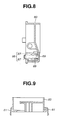
- Fig. 8 is a cross sectional view cut away along a line J - J in Fig. 6.
- Fig. 9 is a cross sectional view cut away along a line F - F in Fig. 6.
- Fig. 10 is a rear view of the housing shown in Fig. 6.
- Fig. 11 is a cross sectional view cut away along a line K - K in Fig. 6.
- Fig. 12 is a cross sectional view cut away along a line M - M in Fig. 7.
- Figs. 1 through 3 show a conceptual view representing a principle of structure according to the present invention.
- truncated cone shaped portions b, b have truncated portions faced toward outer directions and are formed in bilaterally symmetric in the vicinity to both ends of a pivotal axle (portion) a.
- Second projection portions c, c are formed on a base or housing H.
- Each of second projection portions c, c is formed of a pin shaped projection having an resiliency and slidably contacted with the corresponding one of truncated cone shaped portions b, b.
- At least two locations of pivotal axle (portion) a are grasped by means of a left and right pair of first projection portions d, d so as to be pivotably supported by means of first projection portions d, d (refer to Fig. 2).
- First projection portions d, d are constituted by an upper and lower pair of hook shaped projections formed on housing H.
- Recessed portions e, e such as letter V shaped recessed surfaces are formed for pivotal axle portion a to be pivotably slid in the proximity to base portions of first projections d, d.
- a biasing device f is fixed to housing H. Biasing device f serves to slide pivotal axle portion a on recessed portions e, e.
- reference sign g denotes a lever portion such as a lock lever of the shift lock mechanism.
- Lever portion g is integrally or separately formed with or from pivotal axle portion a and is orthogonal to pivotal axle (portion) a.
- Lever portion g is pivoted in an X direction shown in Fig. 1 within a window hole or recessed portion W. However, this is an example.
- a rotational part such as a gear may be substituted for lever portion g.
- the movement of pivotal axle portion a is limited as follows: An axial direction (Y shown in Fig. 1) of pivotal axle portion a and a vertical direction thereof (Z shown in Fig. 1) are limited by means of truncated cone shaped portions b, b and second projection portions c, c.
- a forward-and-backward (longitudinal) movement (X shown in Fig. 1) of pivotal axle portion a is limited by means of biasing device f and recessed portions e, e.
- the clearance (or looseness) in the vertical direction (Z) may be limited by means of first projection portions d, d.
- FIG. 4 An example of an application of the above-described principal structure to the shift lock unit of the multi-stage automatic transmission operation device is shown in Fig. 4. That is to say, as shown in Fig. 4, an axial supporting portion 2 orthogonal to a bottom portion of frame 1 made of a synthetic resin to fix frame 1 to a vehicle body so as to support axle portion 4 in parallel to the vehicle body left-and-right direction.
- a select lever 5 a shaft 3 inserted through axle support portion 2 is formed on both end portions of axle portion 4.
- Select lever 5 is pivotably supported in the longitudinal direction of the vehicle body.
- An axle support portion 6 in parallel to the longitudinal direction of the vehicle body is integrally formed.
- a shift lever main body 8 is pivotably supported on axle support portion 6 in a lateral direction of the vehicle body via a shaft 7
- Select lever includes an engagement recess portion 9.
- Engagement recess portion 9 is constituted by a letter U shaped opening with which an engagement convex portion 16 disposed on a side surface of shift lever main body 8 is always engaged.
- a stop lever 10 projected toward the rear side of the vehicle body of engagement recess portion 9 is formed along an inner side surface of frame 1.
- a moderation (peripheral edge) lever 11 of a sector shape is integrally formed with the front side of the vehicle body engagement recess portion 9.
- a moderation portion (peripheral edge portion) 12 including a corrugated projection positioned on a circular locus with axle portion 4 as a center is installed.
- Moderation portion 12 includes a plate spring 14 whose one end is supported on a shaft 13 and whose other end is bent circularly and brought in close contact with moderation portion 12.
- Shaft 13 is disposed in an inner surface of frame 1.
- Select lever 5 is made of a synthetic resin whose material is different from frame 1.
- a shaft 5 is projected from a rear surface of moderation lever 11 to be connected to a shift cable of automatic transmission.
- Shift lever main body 8 has a base portion 8a made of a synthetic resin through which a shaft 7 is penetrated.
- One side portion of base portion 8a is integrally formed or attached with an engagement convex portion 16 which is engaged with engagement recess portion 9 of select lever 5.
- Engagement convex portion 16 is a lateral straight line part projected laterally from the side surface of base portion 8a, both ends of engagement convex portion 16 being always engaged with engagement recess portion 9.
- a metallic pipe 18 having a predetermined length is insert formed on base portion 8a.
- a knob 19 is coupled to an upper end portion of pipe 18.
- a cylindrical portion 20 having an upper opening is integrally formed on base portion 8a.
- a coil spring 21 and a ball or slide portion 22 are inserted into cylindrical portion.
- Slide pin 22 is engaged with a slanted groove slanted toward the lateral direction and formed on a ceiling of frame 1.
- this slanted groove is formed in an arc shape in the longitudinal direction of the vehicle body with axle portion 4 as a center.
- This slanted groove is slanted to always bias shift lever main body 8 toward one of the forward-and-backward (longitudinal) directions, in this embodiment, toward the left side direction. It is noted that two cavities are formed on D and 3 positions so as to give a moderation feeling of the movement to an operator (driver) when the shift lever switches between D and 3 positions.
- Pipe 18 of shift lever main body 8 penetrates through a gate groove 24 of an indicator portion 23.
- indicator portion 23 is described in the United States Patent Application Publication No. US 2003/0074999 A1 (, the disclosure of which is herein incorporated by reference).
- This indicator 23 is provided with a gate groove 24 and a shift range display portion 25 such as P, R, N, D, 3, 2, and 1.
- a lamp house 26 to illuminate shift range display portion 25 is disposed in indicator portion 23.
- a reference numeral 27 denotes a guide plate through which a gate groove 28 is opened in analogy to gate groove 24.
- Guide plate 28 is fixed to a position of frame 1 having a predetermined height to guide the movement to guide the movement of pipe 19 penetrated through the movement of pipe 18 penetrated through gate groove 28. Pipe 18 is penetrated to cover spaces of gate grooves 24 and 28.
- Shift lock unit 30 is provided with at least three engagement projections 61, 61 projected from a bottom surface toward at least shaft 3 side. Engagement projections 61, 61 are engaged with at least three engagement recess portions 1a to make an easy assembly.
- Housing 60 is formed with an axle supporting recess portion 62 housing a pivotal axle portion 74, a housing recess 63 housing lock lever 75, and another housing recess 64 housing an actuator 85, respectively. Housing 60 is attached onto one side surface of frame 1 so that an open side of axle supporting recess portion 62 faces against a window hole 49.
- the axle supporting recess portion 62 is provided with a mutually spaced apart left-and-right pair of graspable projection portions 66, 66 having substantially letter U shapes and constituted by a pair of hook shaped projections.
- Each graspable projection portion 66 has a pair of hook shaped projections projected vertically from an inner bottom portion 65 of axle supporting recess portion 62.
- a pair of hook portions 67 and 67 at tip portions of each graspable projection portion 66 is wide operable and has a resiliency that pivotal axle portion 74 can be grasped.
- projections 69, 69 are formed which form slidably, contact recesses 68, 68 in the vicinity to one side of graspable projections 66, 66.
- a pair of slidably contactable projections 71, 71 are formed at positions outside graspable projection 66 and projection 69 and are constituted by pin shaped projections.
- An engagement portion 72 is formed which fixes a biasing device 80 on an inner side wall 70 located at a bottom side of axle supporting recess portion 62.
- pivotal axle portion 74 is formed with truncated cone shaped portions 77, 77 in the vicinity to both ends of pivotal axle portion 74.
- Each truncated cone shaped portion 77, 77 is slidably contacted with a corresponding slidable contact projection 71, 71.
- Its truncated cone shaped surface thereof 77, 77 is faced toward its outside of pivotal axle supporting portion 74 and the truncated cone shaped portion 77, 77 are symmetrical to each other in the lateral direction (in the axial direction of the pivotal axle portion 74).
- a lock lever 75, an actuator engagement portion 76, and a rotation limitation stopper 78 are formed between the truncated cone shaped portions 77, 77.
- Actuator engagement portion 76 has a flat head portion to receive a flat head screw shaped plunger 86 of actuator 85 so that the pivotal axle portion 74 is easily coupled to actuator 85.
- a rubber ring 78a is attached onto rotation limitation stopper 78.
- One end portion of pivotal axle portion 74 is provided with an eccentric projection 79.
- This pivotal axle portion 74 is pivotally supported on graspable projections (second projections) 66, 66 by inserting an axle portion thereof into projections 67, 67 of housing 60.
- the pivotal axle portion 74 is pivotally slid on the slide contact recess portions 68, 68. It is noted that projection 79 of pivotal axle portion 74 is axially supported on housing 60 so as to be enabled to be separated from one end portion of a release lever 90.
- Release lever 90 has an axle hole 91 so as to be pivotably supported on housing 60 by means of an axle 73 and is biased by means of a spring 92 so that one end portion 93 of release lever 90 is always spaced apart from eccentric projection 79.
- the other end portion 94 of release lever 90 is contacted with a lower end portion of a pin 46 whose upper end portion is exposed to indicator portion 23. It is noted that pin 46 is disclosed in a United States Patent Application Publication No. US 2003/0074999 A1 published on April 24, 2003 (, the disclosure of which is herein incorporated by reference).
- Biasing device 80 is formed with integrally coupled torsion springs and has end portions 81, 81 which are slidably contacted with a peripheral surface of pivotal axle portion 74 and both ends thereof are spaced apart from each other. Circular projections 83, 83 are formed on housing recess portion 63 to engage windings 82, 82 of biasing device 80.
- shift lever main body 8 when shift lever main body 8 is shifted toward the left direction of the vehicle body, the shift lever main body 8 can be shifted to 3 (third range) position.
- the engagement convex portion 16 of shift lever main body 8 is moved in the left-and-right directions but is not disengaged from engagement recess portion 9 of select lever 5.
- Shift lever main body 8 and select lever 5 are always pivoted integrally for the forward-and-backward directions. It is noted that, in a case where a manual shift groove is installed outside of gate groove 24 of D position, shift lever main body 8 is disengaged from select lever 5 so as to be shifted in the forward-and-backward directions. Hence, a manual sense of driving may be achieved.
- actuator 85 does not operate and its plunger 86 is projected by means of a spring force of a built-in spring. Then, when actuator engagement portion 76 is pivoted in the upward direction through the predetermined angle with the axle of pivotal axle portion as the center, lock lever 75 is slanted in an inner side of frame 1 from window hole 49 so as to block the movement of stop lever 10. That is to say, the side surface of stop lever 10 located at the front side of the vehicle body is contactable with the side surface of lock lever 75 located at the rear side of the vehicle body.
- lock lever 75 is projected toward the inner portion of frame 1 when the vehicle traveling is stopped and parked so that the park lock of the shift lever is carried out.
- lock lever 75 is projected toward the inner portion of frame 1 so that R inhibit N lock of shift lever (8) is carried out.
- pivotal axle portion 74 when pivotal axle portion 74 is revolved, the movements in the axial direction and vertical direction of pivotal axle (portion) 74 are limited by means of truncated cone shaped portions 77, 77 and slide contactable projections 71, 71 and the movement of the forward-and-backward (longitudinal) direction thereof is limited by means of biasing device 80 and slide contactable recess portions 68, 68.
- biasing device 80 slide contactable recess portions 68, 68.
- the lever portion includes lock lever 75 of the operation device of the multi-stage automatic transmission, the operation device of the multi-stage automatic transmission comprising: frame 1 to be fixed to a vehicle body; and shift lever 18, 19 supported so as to enable a shift in both of longitudinal and lateral directions of the vehicle body, the multi-stage automatic transmission being capable of carrying out a park lock when the shift lever is placed at the P position and the R inhibit when the shift lever having an axle portion in parallel to the lateral direction of the vehicle body on which select lever 5 is disposed, shift lever main body 8 integrated to the axle portion and being disposed on another axle portion which is parallel to the longitudinal direction of the vehicle body, the select lever having engagement recess portion 9 which is always enabled to be engaged with an engagement convex portion 16 disposed on a side surface of the shift lever main body and having stop (or stopper) lever 10 projected along the side wall of the frame, the front side of the vehicle body of the stop lever and the rear side of the vehicle body thereof being disposed to be contacted with lock lever 75 which is advanced or retracted
Landscapes
- Engineering & Computer Science (AREA)
- General Engineering & Computer Science (AREA)
- Mechanical Engineering (AREA)
- Arrangement Or Mounting Of Control Devices For Change-Speed Gearing (AREA)
Applications Claiming Priority (2)
| Application Number | Priority Date | Filing Date | Title |
|---|---|---|---|
| JP2003357500 | 2003-10-17 | ||
| JP2003357500A JP2005119517A (ja) | 2003-10-17 | 2003-10-17 | 回動軸部のがた抑え支承構造 |
Publications (1)
| Publication Number | Publication Date |
|---|---|
| EP1524457A2 true EP1524457A2 (fr) | 2005-04-20 |
Family
ID=34373622
Family Applications (1)
| Application Number | Title | Priority Date | Filing Date |
|---|---|---|---|
| EP04024526A Withdrawn EP1524457A2 (fr) | 2003-10-17 | 2004-10-14 | Structure de support sans jeu d'un axe pivotant utilisable dans une unité de verrouillage des changements de vitesses d'une transmission automatique à plusieurs rapports |
Country Status (3)
| Country | Link |
|---|---|
| US (1) | US7406893B2 (fr) |
| EP (1) | EP1524457A2 (fr) |
| JP (1) | JP2005119517A (fr) |
Families Citing this family (5)
| Publication number | Priority date | Publication date | Assignee | Title |
|---|---|---|---|---|
| JP2011225200A (ja) * | 2010-03-30 | 2011-11-10 | Fuji Kiko Co Ltd | シフトレバー装置 |
| JP5909056B2 (ja) * | 2011-06-21 | 2016-04-26 | 津田工業株式会社 | シフトレバーユニット |
| KR101397591B1 (ko) * | 2012-12-14 | 2014-05-20 | 주식회사 에스엘 서봉 | 차량용 변속 장치 |
| JP2015123912A (ja) * | 2013-12-27 | 2015-07-06 | 富士機工株式会社 | シフトレバー装置 |
| CN113840992B (zh) * | 2019-04-10 | 2022-09-09 | 北美日产公司 | 换档器组件、换档锁保护方法及换档锁定杆 |
Citations (1)
| Publication number | Priority date | Publication date | Assignee | Title |
|---|---|---|---|---|
| JP2003127691A (ja) | 2001-10-22 | 2003-05-08 | Fuji Kiko Co Ltd | 多段自動変速機操作装置 |
Family Cites Families (1)
| Publication number | Priority date | Publication date | Assignee | Title |
|---|---|---|---|---|
| JP3703536B2 (ja) | 1995-08-23 | 2005-10-05 | デルタ工業株式会社 | 自動車用チェンジレバーの軸受け構造 |
-
2003
- 2003-10-17 JP JP2003357500A patent/JP2005119517A/ja active Pending
-
2004
- 2004-10-14 EP EP04024526A patent/EP1524457A2/fr not_active Withdrawn
- 2004-10-15 US US10/964,820 patent/US7406893B2/en not_active Expired - Fee Related
Patent Citations (1)
| Publication number | Priority date | Publication date | Assignee | Title |
|---|---|---|---|---|
| JP2003127691A (ja) | 2001-10-22 | 2003-05-08 | Fuji Kiko Co Ltd | 多段自動変速機操作装置 |
Also Published As
| Publication number | Publication date |
|---|---|
| US7406893B2 (en) | 2008-08-05 |
| JP2005119517A (ja) | 2005-05-12 |
| US20050092120A1 (en) | 2005-05-05 |
Similar Documents
| Publication | Publication Date | Title |
|---|---|---|
| JP3889951B2 (ja) | 多段自動変速機操作装置 | |
| US6431339B1 (en) | Transmission shifter with lever-position locking device | |
| US5497673A (en) | Automatic transmission operating device | |
| US6783480B2 (en) | Control device for automatic transmission | |
| US6301994B1 (en) | Shift lever apparatus | |
| US7406893B2 (en) | Clearance-free supporting structure for pivotal axle applicable to shift lock unit of multi-stage automatic transmission | |
| JPH10184868A (ja) | シフトレバーのシフトロック装置 | |
| JP3934358B2 (ja) | シフトレバー装置 | |
| JP4751648B2 (ja) | 車両用シフトロック装置 | |
| US6055881A (en) | Column shift device for automatic transmission | |
| JP4388342B2 (ja) | 自動変速機のシフトレバー装置 | |
| US6427503B2 (en) | Key interlock mechanism for column automatic-transmission operating device | |
| JP3887434B2 (ja) | シフトレバー装置 | |
| JP4888006B2 (ja) | 自動変速機の変速操作装置 | |
| US6155130A (en) | Column shift device for automatic transmission | |
| US12504778B2 (en) | Shift device | |
| JP4063968B2 (ja) | 方向指示レバーのキャンセル機構 | |
| JP3660320B2 (ja) | シフトレバー装置 | |
| JP3732879B2 (ja) | 自動車用チェンジレバーのガイドプレート構造 | |
| JP2000213634A (ja) | ゲ―ト式自動変速機操作装置のシフトロック機構 | |
| JPH09119513A (ja) | 自動変速機操作装置 | |
| JPH1134685A (ja) | 自動変速機の変速操作入力装置 | |
| JPH09183315A (ja) | 自動車用チェンジレバーのノブ取り付け構造 | |
| JPH11170883A (ja) | 自動車用自動変速機のシフト装置 | |
| JPH0537543U (ja) | 自動変速機操作装置の操作レバー支持体 |
Legal Events
| Date | Code | Title | Description |
|---|---|---|---|
| PUAI | Public reference made under article 153(3) epc to a published international application that has entered the european phase |
Free format text: ORIGINAL CODE: 0009012 |
|
| 17P | Request for examination filed |
Effective date: 20041014 |
|
| AK | Designated contracting states |
Kind code of ref document: A2 Designated state(s): AT BE BG CH CY CZ DE DK EE ES FI FR GB GR HU IE IT LI LU MC NL PL PT RO SE SI SK TR |
|
| AX | Request for extension of the european patent |
Extension state: AL HR LT LV MK |
|
| STAA | Information on the status of an ep patent application or granted ep patent |
Free format text: STATUS: THE APPLICATION HAS BEEN WITHDRAWN |
|
| 18W | Application withdrawn |
Effective date: 20090622 |