EP1524462B1 - Soupape électromagnétique compensée pour pression - Google Patents
Soupape électromagnétique compensée pour pression Download PDFInfo
- Publication number
- EP1524462B1 EP1524462B1 EP20040105085 EP04105085A EP1524462B1 EP 1524462 B1 EP1524462 B1 EP 1524462B1 EP 20040105085 EP20040105085 EP 20040105085 EP 04105085 A EP04105085 A EP 04105085A EP 1524462 B1 EP1524462 B1 EP 1524462B1
- Authority
- EP
- European Patent Office
- Prior art keywords
- armature
- pressure
- valve
- solenoid
- pressurizing
- Prior art date
- Legal status (The legal status is an assumption and is not a legal conclusion. Google has not performed a legal analysis and makes no representation as to the accuracy of the status listed.)
- Revoked
Links
- 238000010276 construction Methods 0.000 claims 1
- 238000007789 sealing Methods 0.000 description 10
- 238000010586 diagram Methods 0.000 description 7
- 230000006835 compression Effects 0.000 description 3
- 238000007906 compression Methods 0.000 description 3
- 239000000463 material Substances 0.000 description 3
- XEEYBQQBJWHFJM-UHFFFAOYSA-N Iron Chemical compound [Fe] XEEYBQQBJWHFJM-UHFFFAOYSA-N 0.000 description 2
- 230000001419 dependent effect Effects 0.000 description 2
- 238000011161 development Methods 0.000 description 2
- 230000018109 developmental process Effects 0.000 description 2
- 230000000694 effects Effects 0.000 description 2
- 239000012530 fluid Substances 0.000 description 2
- 239000004020 conductor Substances 0.000 description 1
- 230000007423 decrease Effects 0.000 description 1
- 229910052742 iron Inorganic materials 0.000 description 1
- 239000002655 kraft paper Substances 0.000 description 1
- 239000000696 magnetic material Substances 0.000 description 1
- 230000010355 oscillation Effects 0.000 description 1
- 230000008092 positive effect Effects 0.000 description 1
- 230000001105 regulatory effect Effects 0.000 description 1
Images

Classifications
-
- F—MECHANICAL ENGINEERING; LIGHTING; HEATING; WEAPONS; BLASTING
- F16—ENGINEERING ELEMENTS AND UNITS; GENERAL MEASURES FOR PRODUCING AND MAINTAINING EFFECTIVE FUNCTIONING OF MACHINES OR INSTALLATIONS; THERMAL INSULATION IN GENERAL
- F16K—VALVES; TAPS; COCKS; ACTUATING-FLOATS; DEVICES FOR VENTING OR AERATING
- F16K31/00—Actuating devices; Operating means; Releasing devices
- F16K31/02—Actuating devices; Operating means; Releasing devices electric; magnetic
- F16K31/06—Actuating devices; Operating means; Releasing devices electric; magnetic using a magnet, e.g. diaphragm valves, cutting off by means of a liquid
- F16K31/0686—Braking, pressure equilibration, shock absorbing
- F16K31/0693—Pressure equilibration of the armature
Definitions
- the invention relates to an electromagnet, in particular a switching or proportional solenoid for switching a pilot-operated pressure valve, comprising a housing for receiving and protecting the further solenoid components, at least one arranged in the housing, electrically acted coil for generating a magnetic field, at least one in the magnetic field arranged, linearly movable, designed as an actuator armature with LK: JS two axially opposing armature surfaces and a return device cooperating with the armature, wherein the armature is formed so that it closes or opens a valve seat of a pressure valve cooperating with the electromagnet.
- Such electromagnets are commonly used as a drive unit of valves.
- solenoids When used in valves, a distinction is generally made between solenoids and proportional solenoids.
- proportional solenoids are preferably used. That is why proportional solenoids are also used in pilot-operated pressure control valves.
- electromagnets are known for use in valves. These electromagnets comprise a housing, which surrounds at least one electrically pressurizable coil for generating a magnetic field, and an armature movably arranged in the magnetic field which is designed as an actuator with a valve seat sealing surface and at least one restoring device, which cooperates with the armature and against the Valve seat sealing surface acting force on the anchor brings.
- the return device must be designed so that in addition to be expended for the provision of the actuator without pressurization force required by the pressurization force from the return device must be applied.
- the spring is designed to be larger than would actually be necessary for the generation of a restoring force necessary for sealing.
- the spring thus requires more space, which in total either to larger electromagnets and thus to larger valves or to a suboptimal Exploitation of the space leads, whereby not the largest possible valve nominal width can be produced.
- the anchor is here constructed in several parts and acted upon pressure equalization on opposite anchor surfaces with feed pressure or working pressure.
- a working pressure anchor part is surrounded by a pre-pressure anchor part connected thereto.
- the pre-pressure anchor part is charged on both sides with admission pressure (feed pressure), whereas working pressure is applied to both end faces of the working pressure anchor part. This is achieved by respectively associated through holes.
- the passage opening of the working Schuckankerteils extends coaxially through this, whereas the pre-pressure anchor part has an off-center longitudinal bore as a through hole.
- the anchor parts are provided with a plurality of bores to perform the functions described above.
- the invention includes the technical teaching that the armature has means for pressure equalization at valve seat side pressure-loaded first anchor surface, so that the LK: hv
- Return device cooperates with a compensation force on a second, the first armature surface opposing armature surface, whereby the return device is interpretable only in accordance with the applied sealing force for the valve seat.
- This solution offers the advantage that an equilibrium pressure applied from one side of the armature is additionally acted upon by an opposing counterpressure, whereby the two pressures act correspondingly opposite and thus a pressure compensation is created by the pressure acting alone the force of the reset device.
- This reset device can thus optimally interpret the corresponding requirements and accordingly can also be the space for the return device, so that the electromagnet and finally the valve or the corresponding device with which the solenoid cooperates design.
- an armature in the electromagnet is cylindrically formed with two end faces, which are arranged axially to one another.
- An end face is formed to close a valve seat of a valve cooperating with the solenoid.
- the return device may be formed as a spring-storage unit and acts against the valve-side pressure.
- a further measure improving the invention provides that the means comprise at least one line which directs the pressure applied to the first armature surface on the valve side first armature surface counteracting second armature surface, so that a back pressure against the valve side pressure applied works, is realized. Due to the forwarding of the pressure applied to the first armature surface to the second armature surface, essentially the same pressure acts on both armature sides independently of the pressure value. As a result, a pressure relief or pressure equalization can be realized in a simple manner.
- the second armature surface which can be acted upon by the counter-pressure, is essentially designed such that it has a substantially equal area in the axial direction, such as the pressure-exerted valve-side first armature surface, to equalize the pressure to realize the anchor.
- the first armature surface is acted upon by a pressure p 1 which acts on the first armature surface with the surface area or area cross section A 1 .
- p 1 acts on the first armature surface with the surface area or area cross section A 1 .
- F 1 acts on the valve side acts on the armature or the actuator.
- the force F 1 is directed in the axial direction of the armature in the direction of the second armature surface.
- the second armature surface is acted upon by a pressure p 2, which acts on the second armature surface with the surface area or surface area A 2 .
- a pressure p 2 acts on the second armature surface with the surface area or surface area A 2 .
- This results in a second force F 2 which acts on the armature or the actuator.
- the force F 2 is directed in the axial direction of the armature opposite to the first armature surface.
- the restoring force F R of the restoring device acts on the second armature surface axially in the direction of the first armature surface. This corresponds to a necessary sealing force F A which acts opposite to F R.
- the sealing force F A is determined exclusively by the restoring force F R of the restoring device when the magnetic field is not active. An effect of the pressure is thus not given.
- a further improvement of the invention measure can be achieved in that the line is designed as a longitudinally coaxial extending through the armature straight passage opening to realize the pressure equalization.
- the line is integrated into the armature, whereby the electromagnet builds small, since no additional space for a piping system is needed. It also requires no additional material, which further has the positive effect of making the entire electromagnet easier to build.
- this passage opening at the same time provides the shortest imaginable way to the realization a pressure equalization according to the invention.
- the passage opening is preferably formed as a cylindrical through hole.
- the armature is formed at least two parts with an axially movable in the magnetic field Vordruckankerteil and the Vorpecializingankerteil at least partially surrounding axially immovably connected to the Vortikankerteil Häyakankerteil, thus no relative movement between Vortikankerteil and working pressure anchor is possible, wherein Vortikankerteil and working pressure anchor each have at least one passage opening to realize the pressure equalization.
- the solenoid can be used with pilot operated valves. It is conceivable analogous that the armature is designed in several parts, which can compensate for the same diameter of stim helpfulem valve seat on Vorpecializingankerteil and the inner diameter of the sealing ring correspondingly different pressurizations accordingly.
- the pre-pressure anchor part and working anchor part are preferably made of different materials, wherein the pre-pressure anchor part is made of non-magnetic material and the working pressure anchor part is made of magnetically highly conductive material such as soft iron.
- the pre-pressure anchor part is arranged at least partially axially immovable in the passage opening for pressure equalization of the working pressure anchor.
- the passage opening of the working pressure armature is arranged centrally.
- the passage opening can by two additional axial channels in the working pressure armature or by a thread-like channel in the working pressure anchor part or outside on the form anchor part be educated.
- the game between the guide bush and the working pressure anchor part could be used as a conduit for the working pressure to realize a pressure equalization of the working pressure anchor.
- the restoring device is designed as a compression spring, which is arranged in a serving as a pressure chamber clearance between the housing and anchor to transmit a spring force and caused by the pressure prevailing in the pressure chamber back pressure force on the armature.
- the restoring force which is designed here as a spring force, determines exclusively the sealing force of the armature.
- the spring force preferably acts in the axial direction.
- the compression spring can be arranged to save space in the free space, so that a small-sized electromagnet is realized. Due to the pressure equalization a correspondingly small designed spring can be used, so that the space is optimally utilized.
- the diameter of the valve seat must be equal to the inner diameter of the sealing ring on the Vorpecializingankerteil.
- Another object of the present invention is to provide a pressure valve with optimized space, which allows a stable control loop despite the small dimensions when used in a control system.
- the invention further includes the technical teaching that a pressure valve, in particular a pilot-operated proportional solenoid valve comprises at least one electromagnet according to one of claims 1 to 7, in order to realize a pressure-balanced pressure valve.
- a pressure valve with optimized space and stable control loop can be realized.
- a pressure regulating valve and preferably a pressure-controlled valve can be used Realize pressure control valve, which has a lower magnetic weight and thus a more stable control circuit due to the pressure compensation.
- Fig. 1 shows a plan view of an electromagnet 1 according to the invention with a housing surrounding the electromagnet components 2.
- the electrical housing 2 is cup-shaped with a lid portion and a wall portion, wherein the wall portion in the axial direction has an annular cross-section. It is also possible to arrange the solenoid components in an elongate housing.
- an anchor 3 is arranged.
- the armature 3 is arranged along the central axis of the electromagnet 3 linearly or axially movable.
- the anchor is in two parts with a working pressure anchor part 3a and a pre-pressure anchor part 3b.
- the armature 3 has means for pressure equalization, which are formed as a passage opening 4.
- two-part Anchor 3 the working pressure anchor part 3a a first passage opening 4a and the pre-pressure anchor part 3b has a second passage opening 4b.
- the passage openings 4a, 4b are formed centrally on the corresponding anchor parts 3a, 3b, or the passage opening 4a is screwed thread-shaped outside on the corresponding anchor part 3b. That is, the passage opening 4 a formed as a channel may also be formed thread-shaped or as parallel to the passage opening 4 b formed as a bore.
- the pre-pressure anchor part 3b is arranged axially immovably in the first passage opening 4a. Furthermore, in Fig. 1 a section line A-A shown. The sectional view is in the following Fig. 2 shown.
- Fig. 2 shows the section A-A of the in Fig. 1
- the cup-shaped design of the housing 2 can be seen clearly, wherein the thickness of the housing wall is formed substantially constant.
- the solenoid components are arranged in an elongated housing.
- the working pressure anchor part 3a is annular or tubular with an annular cross-section, that is designed as a cylinder with a central first passage opening 4a.
- the pre-pressure anchor part 3b is arranged, which also has a central, cylindrical second passage opening 4b.
- the front side arranged first armature surface 5b is formed as a valve seat and has a corresponding geometry.
- an electrically pressurizable coil 6 is arranged, which forms a magnetic field when flowing through electric current.
- the coil 6 surrounds the two armature parts 3a, 3b, so that they are arranged within the magnetic field formed by the coil 6, when subjected to electric current.
- the anchor part 3a is formed of a material cooperating with the magnetic field, so that the anchor parts 3a and 3b are movable by the magnetic field.
- a guide bush is provided which surrounds the working pressure anchor part 3a.
- the pre-pressure anchor portion 3b is formed by the working pressure anchor portion 3a, which is cylindrical and has a through hole.
- the working pressure anchor part 3a is firmly connected to the working pressure anchor part 3b, so that no relative movement is possible between the two working pressure anchor parts.
- the pole piece bears against the inside of the housing 2, more precisely the cover area of the housing 2, and forms a free space 7, into which the pre-pressure anchor portion 3b opens with a second armature surface 8b.
- a compression spring return device 9 is arranged, which cooperates with the pre-pressure anchor part 3b.
- the return device 9 rests against the inside of the cover area of the housing 2 and against a shoulder of the pre-pressure armature part 3b and thus acts on the pre-pressure anchor part 3b.
- the free space 7 and the rear O-ring 10 can be acted upon by a pressure p which corresponds to the pressure p (not shown) on the part of the valve.
- a pressure p which corresponds to the pressure p (not shown) on the part of the valve.
- the first armature surface 5a and the cross-sectional area surrounding the second through-hole 4b acts.
- the armature surface 5b, the cross-sectional area around the second through-hole 4b and the inner-diameter surface of the O-ring 10 are made equal in area, so that the armature surface 5b and the inner diameter surface of the O-ring 10 have the same but oppositely directed thrust force.
- a clearance 7 is formed, which is acted upon by a valve-side pressure p A through the first passage opening 4a longitudinally through the working pressure armature part 3a.
- the working pressure armature part 3a has a second armature surface 8a, which corresponds to the surface area of the first armature surface 5a.
- both anchor surfaces 5a, 8a equal to the amount, but oppositely directed Compressive force.
- the two free spaces 7 are sealed from each other by means of a sealing ring.
- the pre-pressure anchor part 3b is connected to the component via a non-metallic O-ring retaining disk.
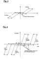
- Fig. 3 shows a flow-force diagram of a pressure valve according to the invention.
- Fig. 4 a flow-force diagram of a conventional pressure valve.
- a characteristic curve is shown during operation of the pressure valve.
- Fig. 3 has a hysteresis curve while Fig. 4 has two horizontally shifted hysteresis curves.
- the characteristic in Fig. 3 runs opposite to the characteristic in Fig. 4 with a flatter rise, wherein the characteristic curve corresponds approximately to a parallelogram, that is to say in the manner of a hysteresis curve.
- two such curves can be seen, both of which have a steeper slope.
- the characteristic curve in Fig. 3 due to the pressure compensation has no fluctuations in the closing forces, that is, the closing forces are constant due to the pressure equalization at all valve-side pressures.
- the power reserve in dynamic behavior of the valve is large, since no additional forces for the safe closing of the armature must be applied to the valve seat of the reset device.
- the forces to be applied by the electromagnet are also lower for opening. From the above results in a generally flatter characteristic curve, which can be better controlled than a steeper characteristic, since with a small deviation in one direction of the diagram, the effects in the other direction of the diagram are significantly lower than with steeper characteristics.
- the better control makes it easier to regulate disturbances or oscillations of the system, so that overall a less interference- and vibration-prone system is realized.
- FIG. 4 Diagram showing the behavior of a non-pressure-relieved system has two mutually shifted curves.
- the characteristic shift results from pre-pressure fluctuations so that a characteristic field (see FIG. 6) arises. This results in several work areas.
Landscapes
- Engineering & Computer Science (AREA)
- General Engineering & Computer Science (AREA)
- Mechanical Engineering (AREA)
- Magnetically Actuated Valves (AREA)
Claims (6)
- Électroaimant (1) pour commuter une soupape à pression pilotée, comprenant un boîtier (2) pour recevoir au moins une bobine électrique (6) destinée à générer un champ magnétique, dans lequel est agencé un induit (3) mobile de façon linéaire, qui présente deux surfaces d'induit subdivisées (5a, 5b ; 8a, 8b) axialement opposés et qui coopèrent avec un dispositif de rappel (9), dans lequel l'induit (3) ferme ou ouvre un siège de soupape d'une soupape à pression coopérant avec l'électroaimant (1), dans lequel, pour compenser la pression sur l'induit (3), le dispositif de rappel (9) agit avec une force de compensation conjointement sur la seconde surface d'induit (8a, 8b), ce pourquoi l'induit (3) est réalisé au moins en deux parties avec une partie d'induit à pression pilote (3b) déplaçable axialement dans le champ magnétique et une partie d'induit (3a) à pression de travail, qui entoure au moins partiellement la partie d'induit à pression pilote (3b) et est reliée sans possibilité de déplacement axial à la partie d'induit à pression pilote (3b), dans lequel la partie d'induit à pression pilote (3b) et la partie d'induit à pression de travail (3a) comportent chacune au moins une ouverture traversante (4a, 4b),
caractérisé en ce que la partie d'induit à pression pilote (3b) est agencée sans possibilité de déplacement axial au moins partiellement dans l'ouverture traversante (4a) pour la compensation de pression de la partie d'induit à pression de travail (3a). - Électroaimant (1) selon la revendication 1,
caractérisé en ce que les moyens comprennent au moins une conduite qui amène la pression appliquée côté soupape à la première surface d'induit (5a, 5b) vers une seconde surface d'induit (8a, 8b) qui agit à l'encontre de la première surface d'induit (5a, 5b) côté soupape, de sorte qu'il se produit une contrepression qui agit à l'encontre de la pression appliquée du côté soupape. - Électroaimant (1) selon la revendication 1 ou 2,
caractérisé en ce que la seconde surface d'induit (8a, 8b) soumise à la contrepression est sensiblement réalisée de telle façon que celle-ci présente en direction axiale une surface sensiblement égale à la première surface d'induit (5a, 5b) du côté soupape, sollicitée avec la pression, afin de réaliser la compensation de pression de l'induit (3). - Électroaimant (1) selon l'une des revendications précédentes 1 à 3,
caractérisé en ce que la conduite est réalisée sous forme d'une ouverture traversante (4) rectiligne qui s'étend en longueur coaxialement à travers l'induit (3), afin de réaliser la compensation de pression. - Électroaimant (1) selon l'une des revendications précédentes 1 à 4,
caractérisé en ce que le dispositif de rappel (9) est réalisé sous forme de ressort de compression qui est agencé dans un espace libre (7) entre le boîtier (2) et l'induit (3) qui sert simultanément de chambre de pression, afin de transmettre à l'induit (3) une force qui résulte de la force du ressort et de la contrepression qui règne dans l'espace libre (7). - Soupape à pression, en particulier soupape magnétique proportionnelle pilotée, comprenant au moins un électroaimant (1) selon l'une des revendications 1 à 7, afin de réaliser une soupape à pression compensée en pression.
Applications Claiming Priority (2)
| Application Number | Priority Date | Filing Date | Title |
|---|---|---|---|
| DE10348171 | 2003-10-16 | ||
| DE2003148171 DE10348171A1 (de) | 2003-10-16 | 2003-10-16 | Elektromagnet und Druckventil mit Elektromagnet zum Schalten eines vorgesteuerten Druckventils |
Publications (2)
| Publication Number | Publication Date |
|---|---|
| EP1524462A1 EP1524462A1 (fr) | 2005-04-20 |
| EP1524462B1 true EP1524462B1 (fr) | 2010-06-23 |
Family
ID=34353441
Family Applications (1)
| Application Number | Title | Priority Date | Filing Date |
|---|---|---|---|
| EP20040105085 Revoked EP1524462B1 (fr) | 2003-10-16 | 2004-10-15 | Soupape électromagnétique compensée pour pression |
Country Status (2)
| Country | Link |
|---|---|
| EP (1) | EP1524462B1 (fr) |
| DE (2) | DE10348171A1 (fr) |
Families Citing this family (1)
| Publication number | Priority date | Publication date | Assignee | Title |
|---|---|---|---|---|
| CN111173800B (zh) * | 2019-12-16 | 2021-09-17 | 河南平高电气股份有限公司 | 一种液压操动机构用电液控制阀及其电磁先导阀和先导阀 |
Family Cites Families (3)
| Publication number | Priority date | Publication date | Assignee | Title |
|---|---|---|---|---|
| CH624196A5 (en) * | 1977-08-17 | 1981-07-15 | Ernst Franz Voegeli | Solenoid valve |
| DE3925794C2 (de) * | 1989-08-04 | 1996-03-14 | Bosch Gmbh Robert | Elektromagnetventil |
| US6832748B2 (en) * | 2001-12-05 | 2004-12-21 | Cummins Inc. | Outwardly opening, seat-sealed, force balanced, hydraulic valve and actuator assembly |
-
2003
- 2003-10-16 DE DE2003148171 patent/DE10348171A1/de not_active Withdrawn
-
2004
- 2004-10-15 DE DE200450011302 patent/DE502004011302D1/de not_active Expired - Lifetime
- 2004-10-15 EP EP20040105085 patent/EP1524462B1/fr not_active Revoked
Also Published As
| Publication number | Publication date |
|---|---|
| EP1524462A1 (fr) | 2005-04-20 |
| DE10348171A1 (de) | 2005-05-25 |
| DE502004011302D1 (de) | 2010-08-05 |
Similar Documents
| Publication | Publication Date | Title |
|---|---|---|
| DE60104248T2 (de) | Nach beiden RIchtungen vorgesteuerte Ventilanordnung | |
| DE69715712T2 (de) | Hydraulisches Elektromagnetventil | |
| DE3708248A1 (de) | Wegeventil | |
| DE60301986T2 (de) | Elektrisch betriebene hydraulische Stellvorrichtung mit positionsabhängiger Kraftrückkoplung | |
| DE112009005460B4 (de) | Elektromagnetisches linearventil | |
| DE102005058846A1 (de) | Ventilbaukastensystem mit elektromagnetisch betätigtem Ventil | |
| EP0681128A1 (fr) | Electrovanne | |
| DE112018003806T5 (de) | Stoßdämpfer | |
| DE68916435T2 (de) | Schnell ansprechendes, druckausgeglichenes, elektromagnetisches hochdruck-steuerventil. | |
| DE602004006563T2 (de) | Magnetischer Betätiger | |
| DE2952237A1 (de) | Drucksteuerventil | |
| DE102019117233A1 (de) | Druckrückführkolben mit Ringschulter | |
| DE69617591T2 (de) | Direkt gekuppeltes Magnetventil | |
| DE4423103C2 (de) | Elektromagnetisch beetätigbares Ventil | |
| DE3305092A1 (de) | Druckregelventil | |
| EP0667459A1 (fr) | Unité de soupape à électro-aimant proportionnel | |
| EP0093340A2 (fr) | Servovalve électronique pour la commande d'un débit volumique ou d'une pression | |
| DE3329734C2 (fr) | ||
| DE3134065A1 (de) | Druckregelventil | |
| DE19652410A1 (de) | Elektropneumatisches Ventil | |
| DE10305157A1 (de) | Elektromagnetisches Doppelschaltventil | |
| DE102014226623A1 (de) | Druckbegrenzungsventil und damit ausgestattete hydraulische Maschine | |
| EP2813728B1 (fr) | Soupape de robinet à piston | |
| EP1524462B1 (fr) | Soupape électromagnétique compensée pour pression | |
| DE10030059B4 (de) | Steuereinrichtung |
Legal Events
| Date | Code | Title | Description |
|---|---|---|---|
| PUAI | Public reference made under article 153(3) epc to a published international application that has entered the european phase |
Free format text: ORIGINAL CODE: 0009012 |
|
| AK | Designated contracting states |
Kind code of ref document: A1 Designated state(s): AT BE BG CH CY CZ DE DK EE ES FI FR GB GR HU IE IT LI LU MC NL PL PT RO SE SI SK TR |
|
| AX | Request for extension of the european patent |
Extension state: AL HR LT LV MK |
|
| 17P | Request for examination filed |
Effective date: 20050923 |
|
| AKX | Designation fees paid |
Designated state(s): DE FR GB IT |
|
| 17Q | First examination report despatched |
Effective date: 20051115 |
|
| GRAP | Despatch of communication of intention to grant a patent |
Free format text: ORIGINAL CODE: EPIDOSNIGR1 |
|
| GRAS | Grant fee paid |
Free format text: ORIGINAL CODE: EPIDOSNIGR3 |
|
| GRAA | (expected) grant |
Free format text: ORIGINAL CODE: 0009210 |
|
| AK | Designated contracting states |
Kind code of ref document: B1 Designated state(s): DE FR GB IT |
|
| REF | Corresponds to: |
Ref document number: 502004011302 Country of ref document: DE Date of ref document: 20100805 Kind code of ref document: P |
|
| PLBI | Opposition filed |
Free format text: ORIGINAL CODE: 0009260 |
|
| 26 | Opposition filed |
Opponent name: PIERBURG GMBH Effective date: 20110322 |
|
| PLAX | Notice of opposition and request to file observation + time limit sent |
Free format text: ORIGINAL CODE: EPIDOSNOBS2 |
|
| REG | Reference to a national code |
Ref country code: DE Ref legal event code: R026 Ref document number: 502004011302 Country of ref document: DE Effective date: 20110322 |
|
| PLBB | Reply of patent proprietor to notice(s) of opposition received |
Free format text: ORIGINAL CODE: EPIDOSNOBS3 |
|
| PGFP | Annual fee paid to national office [announced via postgrant information from national office to epo] |
Ref country code: FR Payment date: 20121113 Year of fee payment: 9 |
|
| RDAF | Communication despatched that patent is revoked |
Free format text: ORIGINAL CODE: EPIDOSNREV1 |
|
| REG | Reference to a national code |
Ref country code: DE Ref legal event code: R103 Ref document number: 502004011302 Country of ref document: DE Ref country code: DE Ref legal event code: R064 Ref document number: 502004011302 Country of ref document: DE |
|
| PGFP | Annual fee paid to national office [announced via postgrant information from national office to epo] |
Ref country code: GB Payment date: 20121023 Year of fee payment: 9 |
|
| PGFP | Annual fee paid to national office [announced via postgrant information from national office to epo] |
Ref country code: DE Payment date: 20121217 Year of fee payment: 9 |
|
| RDAG | Patent revoked |
Free format text: ORIGINAL CODE: 0009271 |
|
| STAA | Information on the status of an ep patent application or granted ep patent |
Free format text: STATUS: PATENT REVOKED |
|
| 27W | Patent revoked |
Effective date: 20130217 |
|
| GBPR | Gb: patent revoked under art. 102 of the ep convention designating the uk as contracting state |
Effective date: 20130217 |
|
| REG | Reference to a national code |
Ref country code: DE Ref legal event code: R107 Ref document number: 502004011302 Country of ref document: DE Effective date: 20130814 |
|
| PGFP | Annual fee paid to national office [announced via postgrant information from national office to epo] |
Ref country code: IT Payment date: 20131029 Year of fee payment: 10 |