EP1524528A2 - Digitale Vorrichtung zur Erfassung der Winkelgeschwindigkeit - Google Patents
Digitale Vorrichtung zur Erfassung der Winkelgeschwindigkeit Download PDFInfo
- Publication number
- EP1524528A2 EP1524528A2 EP04256315A EP04256315A EP1524528A2 EP 1524528 A2 EP1524528 A2 EP 1524528A2 EP 04256315 A EP04256315 A EP 04256315A EP 04256315 A EP04256315 A EP 04256315A EP 1524528 A2 EP1524528 A2 EP 1524528A2
- Authority
- EP
- European Patent Office
- Prior art keywords
- electrodes
- angular velocity
- detection device
- rotor
- velocity detection
- Prior art date
- Legal status (The legal status is an assumption and is not a legal conclusion. Google has not performed a legal analysis and makes no representation as to the accuracy of the status listed.)
- Withdrawn
Links
Images


Classifications
-
- G—PHYSICS
- G01—MEASURING; TESTING
- G01C—MEASURING DISTANCES, LEVELS OR BEARINGS; SURVEYING; NAVIGATION; GYROSCOPIC INSTRUMENTS; PHOTOGRAMMETRY OR VIDEOGRAMMETRY
- G01C19/00—Gyroscopes; Turn-sensitive devices using vibrating masses; Turn-sensitive devices without moving masses; Measuring angular rate using gyroscopic effects
- G01C19/02—Rotary gyroscopes
-
- G—PHYSICS
- G01—MEASURING; TESTING
- G01C—MEASURING DISTANCES, LEVELS OR BEARINGS; SURVEYING; NAVIGATION; GYROSCOPIC INSTRUMENTS; PHOTOGRAMMETRY OR VIDEOGRAMMETRY
- G01C19/00—Gyroscopes; Turn-sensitive devices using vibrating masses; Turn-sensitive devices without moving masses; Measuring angular rate using gyroscopic effects
- G01C19/56—Turn-sensitive devices using vibrating masses, e.g. vibratory angular rate sensors based on Coriolis forces
- G01C19/5705—Turn-sensitive devices using vibrating masses, e.g. vibratory angular rate sensors based on Coriolis forces using masses driven in reciprocating rotary motion about an axis
- G01C19/5712—Turn-sensitive devices using vibrating masses, e.g. vibratory angular rate sensors based on Coriolis forces using masses driven in reciprocating rotary motion about an axis the devices involving a micromechanical structure
-
- G—PHYSICS
- G01—MEASURING; TESTING
- G01P—MEASURING LINEAR OR ANGULAR SPEED, ACCELERATION, DECELERATION, OR SHOCK; INDICATING PRESENCE, ABSENCE, OR DIRECTION, OF MOVEMENT
- G01P15/00—Measuring acceleration; Measuring deceleration; Measuring shock, i.e. sudden change of acceleration
- G01P15/02—Measuring acceleration; Measuring deceleration; Measuring shock, i.e. sudden change of acceleration by making use of inertia forces using solid seismic masses
- G01P15/08—Measuring acceleration; Measuring deceleration; Measuring shock, i.e. sudden change of acceleration by making use of inertia forces using solid seismic masses with conversion into electric or magnetic values
- G01P15/0888—Measuring acceleration; Measuring deceleration; Measuring shock, i.e. sudden change of acceleration by making use of inertia forces using solid seismic masses with conversion into electric or magnetic values for indicating angular acceleration
Definitions
- the present disclosure relates to a digital angular velocity detection device that uses a micro electro mechanical system (MEMS).
- MEMS micro electro mechanical system
- a general digital angular velocity detection device such as a gyroscope measures rotation angle with respect to a rotation direction of an object, and is usually used in the navigation devices in a ship or an aircraft.
- the gyroscope measures the angular velocity based on a principle that a Coriolis force is applied vertically to the rotation direction.
- semiconductor technology is developed, the gyroscope has been produced using MEMS technology.
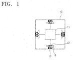
- FIG. 1 explains the operation principle of a micro gyroscope using the general MEMS technology.
- the micro gyroscope is constituted by a vibratory mass 11, and a movable electrode 12 connected to the mass 11, This causes variations in the electrostatic capacitance with a fixed electrode 13 as a rotation force is applied to the mass 11 in a vertical direction to the vibration thereof.
- An elastic member 14 is connected between the movable electrode 12 and the fixed electrode 13.
- a housing 10 supports the fixed electrode 13.
- the Coriolis force is given in a vertical direction to the rotation force.
- a distance between the movable electrode 12 and the fixed electrode 13 decreases. This reduction in distance generates a variation of the electrostatic capacitance there between.
- the micro gyroscope measures variation of the angular velocity by converting the electrostatic capacitance variation to a voltage variation.
- the above-structured micro gyroscope needs to keep the mass 11 vibrating continually for the measurement of the angular velocity variation. Therefore, if the rotation force is not applied from the outside, the vibration of the mass 11 itself can cause a measurement error. Further, in order to generate and measure the capacitance variations between the movable electrode 12 and the fixed electrode 13, the distance between the-movable electrode 12 and the fixed electrode 13 needs to be as short as possible. On the other hand, a contact area therebewteen should be large. Such a requirement complicates the structure of the three-dimensional electrode and the fixed electrode.
- FIG. 2 shows a related art structure of the electrodes constituting the micro gyroscope of FIG. 1.
- the distance between the movable electrode 12 and the fixed electrode 13 is very short to guarantee sufficient capacitance between them. Further, the movable electrode 12 and the fixed electrode 13 are disposed very high from a semiconductor substrate. The manufacturing process to make such a three-dimensional structure using semiconductor technology is very complex. Moreover, it is hard to keep the distances between the movable electrode 12 and the fixed electrode 13 regular.
- a digital angular velocity detection device comprising:
- the invention provides a micro gyroscope having a simple structure and an improved accuracy.
- the disclosed teachings provide a digital angular velocity detection device, comprising a stator formed on a substrate.
- a rotor operable to rotate in response to an inertial force is provided.
- the rotor has a plurality of electrodes formed at regular intervals on a curve at a predetermined radius away from a center of the rotor.
- a detector having detection electrodes facing the plurality of electrodes is provided.
- the detection electrodes are operable to detect a rotation angle of the rotor based on a number of electrostatic capacitance variations generated between the plurality of electrodes and the detection electrodes.
- the device further includes a ring-shaped first coil through which a pulse is applied from outside, and a second coil facing the first coil that has an induced pulse generated by an electromagnetic induction.
- the plurality of electrodes are connected to each other by a conducting wire and the plurality of electrodes connected by the conducting wire is operable to generate the induced pulse on the second coil.
- stator the stator, the rotor, and the detector are formed on a semiconductor substrate.
- a digital angular velocity detection device comprising:
- the light beam projection device is disposed on a line linking parts of the curve, and has a plurality of light beam projectors for projecting the beam.
- the light beam projectors are disposed at predetermined intervals on the line.
- FIGS. 3A and 3B explain a basic concept of a digital gyroscope embodying aspects of the disclosed teachings.
- a plurality of electrodes 100a to 100n which are electrically connected, are disposed at certain intervals on a copper wire which rotates in response to a rotation force applied from the outside.
- a detector 110 is provided opposite to the electrodes 100a to 100n.
- the electrodes 100a to 100n are formed toward the detector 110 having a saw teeth part to generate variations of the electrostatic capacitance when the electrodes 100a to 100n neighbors the detector 110.
- the digital gyroscope may comprise an angular velocity calculation circuit that calculates the angular velocity by converting the detected rotation angle to a rotation angle per a certain time unit.
- FIG. 3B shows an exemplary embodiment of the digital gyroscope according to the basic concept of FIG. 3A.
- the illustrated digital gyroscope comprises a rotor and a stator 150.
- the stator 150 comprises a first coil 151 for sending a pulse applied from the outside.
- the rotor comprises a second coil 101 facing the first coil 151.
- a conducting wire 100 connects the electrodes 100a to 100n and the second coil 101.
- the pulse sent to the first coil 151 induces a pulse at the second coil 101 of the rotor by an electromagnetic induction.
- the pulse induced to the rotor is applied to the respective electrodes 100a to 100n that are connected through the conducting wire 100. Therefore, the rotor does not need a separate structure to apply a pulse from the outside. Accordingly, the structure is simplified, thereby increasing the reliability increases.
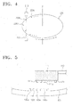
- FIG. 4 shows another exemplary embodiment of the disclosed digital gyroscope.
- the digital gyroscope in FIG. 4 detects the rotation angle using a photo detection method. It comprising a rotation board 200 with holes 200a to 200c formed at certain intervals in the exterior of the rotation board 200.
- a light beam projection device 210 projects a beam to the holes 200a to 200c.
- a detector 220 detects the light beam projected from the light beam projection device 210 to any one of the holes 200a to 200c.
- the rotation board 200 rotates in a direction "A"
- the light beam projected from the light beam projection device 210 penetrates some of the holes 200a to 200c.
- the detector 220 detects the rotation angle of the rotation board 200 based on the level of brightness changes occurring due to the rotation of the rotation board 200.
- the detector 220 may be a photo detector such as a phototransistor or a photodiode, which is capable of detecting the beam.
- FIG. 5 is a detailed view of the structure of the digital gyroscope of FIG. 3A.
- electrodes 100a to 100n are disposed on a portion at a predetermined radius away from a center axis Z of the rotor.
- the electrodes 100a to 100n are electrically connected.
- a detector 110 is formed at an upper part of the rotor.
- a head 111 is formed at an end of the detector 110, and has a plurality of detection electrodes 111a to 111n to face one of the electrodes 200a to 200c. Distances between the respective detection electrodes 111a to 111n are more than distances between the respective electrodes 100a to 100n. As a result, the detection electrodes 111a to 111n are not aligned with the electrodes 100a to 100n altogether when the rotor rotates in the direction "A".
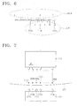
- FIG. 6 explains a principle for calculating a rotation angle of the rotor 100 by detection electrodes 111a to 111n formed at a detector 110 of FIG. 5.
- Main scale is illustrated on an upper part in FIG. 6, and sub scale is on a lower part.
- Numbers 1, 2, and 3 respectively represent 10, 20, 30nm.
- the marks of the main scale are at 1nm intervals.
- Setting 20nm of the main scale as a unit, the sub scale is 19nm in length. This is based on a Vernier Calipers' principle for measuring length of an object, wherein resolution varies according to the number of the marks on the sub scale with respect to the unit length of the main scale.
- a 0-mark on the sub scale is between 12nm and 13nm on the main scale, and 4-mark on the sub scale is lined up with the 2-mark on the main scale. To read this according to the Vernier Calipers' principle, 12.4nm is obtained.
- the measuring method of the digital gyroscope of FIG. 5 is described as follows.
- the detection electrode 111a formed on the head 111 faces the electrode 100c.
- the electrostatic capacitance changes between the electrode 100c and the fixed electrode 111a.
- the electrodes 100a to 100n of the digital gyroscope in FIG. 5 function as the marks on the main scale shown in FIG. 6, and the fixed electrodes 111a to 111n function as the marks on the sub scale.
- FIG. 7 shows a detailed structure of the digital gyroscope of FIG. 4.
- the digital gyroscope of FIG. 7 comprises a light beam projection device 210.
- a rotation board 200 rotates corresponding to the rotation force from the outside, and has holes 200a to 200n.
- a detector 220 detects the beam penetrated through the holes 200a to 200n.
- Light beam projectors 1 to n are provided at the light beam projection device 210, and detectors 220a to 220n are disposed to face each other. That is, when the beam penetrates through the holes 200a to 200n, one of the detectors 220a to 220n corresponding to the penetrated location reacts to the beam.
- a distance between the light beam projectors 1 to n formed at the light beam projection device 210, and a distance between the grooves 200a to 200n per unit length formed at the rotation board 200 are calculated using the equation below.
- the holes 200a to 200n of the digital gyroscope function as the marks on the main scale of FIG. 6, and the detectors 220a to 220n function as the marks on the sub scale.
- the number of the holes in the digital gyroscope dose not have to correspond to the resolution of the rotation board 200 to enhance the resolution for the detection of the rotation angle.
- Superior resolution can be obtained by increasing the number of the light beam projectors 1 to n, and the number of the detectors 220a to 220n which detect the light beam projected from the light beam projectors 1 to n toward the rotation board 200.
- the micro gyroscope using a MEMS technology does not require a complex structure for superior resolution, therefore improving reliability of the structure and the resolution.
- the angular velocity detection device of the above structure can be used for measuring angular velocity as well as for detecting rotation angle.
Landscapes
- Physics & Mathematics (AREA)
- General Physics & Mathematics (AREA)
- Engineering & Computer Science (AREA)
- Radar, Positioning & Navigation (AREA)
- Remote Sensing (AREA)
- Gyroscopes (AREA)
- Transmission And Conversion Of Sensor Element Output (AREA)
Applications Claiming Priority (2)
| Application Number | Priority Date | Filing Date | Title |
|---|---|---|---|
| KR2003071066 | 2003-10-13 | ||
| KR1020030071066A KR100693347B1 (ko) | 2003-10-13 | 2003-10-13 | 디지털 회전형 각속도 검출장치 |
Publications (2)
| Publication Number | Publication Date |
|---|---|
| EP1524528A2 true EP1524528A2 (de) | 2005-04-20 |
| EP1524528A3 EP1524528A3 (de) | 2006-11-15 |
Family
ID=34374263
Family Applications (1)
| Application Number | Title | Priority Date | Filing Date |
|---|---|---|---|
| EP04256315A Withdrawn EP1524528A3 (de) | 2003-10-13 | 2004-10-13 | Digitale Vorrichtung zur Erfassung der Winkelgeschwindigkeit |
Country Status (4)
| Country | Link |
|---|---|
| US (1) | US7328616B2 (de) |
| EP (1) | EP1524528A3 (de) |
| JP (1) | JP2005121658A (de) |
| KR (1) | KR100693347B1 (de) |
Families Citing this family (27)
| Publication number | Priority date | Publication date | Assignee | Title |
|---|---|---|---|---|
| US20090310039A1 (en) * | 2008-06-17 | 2009-12-17 | Searete Llc, A Limited Liability Corporation Of The State Of Delaware | Methods and systems for user parameter responsive projection |
| US20100066689A1 (en) * | 2008-06-17 | 2010-03-18 | Jung Edward K Y | Devices related to projection input surfaces |
| US8602564B2 (en) * | 2008-06-17 | 2013-12-10 | The Invention Science Fund I, Llc | Methods and systems for projecting in response to position |
| US8262236B2 (en) * | 2008-06-17 | 2012-09-11 | The Invention Science Fund I, Llc | Systems and methods for transmitting information associated with change of a projection surface |
| US20090312854A1 (en) * | 2008-06-17 | 2009-12-17 | Searete Llc, A Limited Liability Corporation Of The State Of Delaware | Methods and systems for transmitting information associated with the coordinated use of two or more user responsive projectors |
| US20090309826A1 (en) * | 2008-06-17 | 2009-12-17 | Searete Llc, A Limited Liability Corporation Of The State Of Delaware | Systems and devices |
| US20090309828A1 (en) * | 2008-06-17 | 2009-12-17 | Searete Llc, A Limited Liability Corporation Of The State Of Delaware | Methods and systems for transmitting instructions associated with user parameter responsive projection |
| US20110176119A1 (en) * | 2008-06-17 | 2011-07-21 | Searete Llc, A Limited Liability Corporation Of The State Of Delaware | Methods and systems for projecting in response to conformation |
| US8384005B2 (en) * | 2008-06-17 | 2013-02-26 | The Invention Science Fund I, Llc | Systems and methods for selectively projecting information in response to at least one specified motion associated with pressure applied to at least one projection surface |
| US8944608B2 (en) * | 2008-06-17 | 2015-02-03 | The Invention Science Fund I, Llc | Systems and methods associated with projecting in response to conformation |
| US8955984B2 (en) * | 2008-06-17 | 2015-02-17 | The Invention Science Fund I, Llc | Projection associated methods and systems |
| US8308304B2 (en) * | 2008-06-17 | 2012-11-13 | The Invention Science Fund I, Llc | Systems associated with receiving and transmitting information related to projection |
| US8376558B2 (en) * | 2008-06-17 | 2013-02-19 | The Invention Science Fund I, Llc | Systems and methods for projecting in response to position change of a projection surface |
| US20100066983A1 (en) * | 2008-06-17 | 2010-03-18 | Jun Edward K Y | Methods and systems related to a projection surface |
| US8608321B2 (en) * | 2008-06-17 | 2013-12-17 | The Invention Science Fund I, Llc | Systems and methods for projecting in response to conformation |
| US20090310098A1 (en) * | 2008-06-17 | 2009-12-17 | Searete Llc, A Limited Liability Corporation Of The State Of Delaware | Methods and systems for projecting in response to conformation |
| US8936367B2 (en) * | 2008-06-17 | 2015-01-20 | The Invention Science Fund I, Llc | Systems and methods associated with projecting in response to conformation |
| US20090313150A1 (en) * | 2008-06-17 | 2009-12-17 | Searete Llc, A Limited Liability Corporation Of The State Of Delaware | Methods associated with projection billing |
| US8641203B2 (en) * | 2008-06-17 | 2014-02-04 | The Invention Science Fund I, Llc | Methods and systems for receiving and transmitting signals between server and projector apparatuses |
| US20090313151A1 (en) * | 2008-06-17 | 2009-12-17 | Searete Llc, A Limited Liability Corporation Of The State Of Delaware | Methods associated with projection system billing |
| US8723787B2 (en) * | 2008-06-17 | 2014-05-13 | The Invention Science Fund I, Llc | Methods and systems related to an image capture projection surface |
| US8733952B2 (en) * | 2008-06-17 | 2014-05-27 | The Invention Science Fund I, Llc | Methods and systems for coordinated use of two or more user responsive projectors |
| US20090310103A1 (en) * | 2008-06-17 | 2009-12-17 | Searete Llc, A Limited Liability Corporation Of The State Of Delaware | Methods and systems for receiving information associated with the coordinated use of two or more user responsive projectors |
| US8267526B2 (en) * | 2008-06-17 | 2012-09-18 | The Invention Science Fund I, Llc | Methods associated with receiving and transmitting information related to projection |
| WO2010000861A1 (en) * | 2008-07-04 | 2010-01-07 | Ident Technology Ag | Capacitive sensor device |
| US20100033181A1 (en) * | 2008-08-07 | 2010-02-11 | Villanova University | Levitating MEMS Resonator for Magnetic Resonance Force Microscopy |
| CN104985529A (zh) * | 2015-07-28 | 2015-10-21 | 安徽工程大学 | 硅片磨削力动态信号检测装置 |
Citations (4)
| Publication number | Priority date | Publication date | Assignee | Title |
|---|---|---|---|---|
| GB1302609A (de) * | 1970-05-15 | 1973-01-10 | ||
| EP0270440A1 (de) * | 1986-11-21 | 1988-06-08 | Thomson-Csf | Hochpräziser winkel- oder längenkapazitiver Weggeber |
| DE3834200A1 (de) * | 1988-10-07 | 1990-04-12 | Rexroth Mannesmann Gmbh | Kapazitiver wegaufnehmer |
| US6507016B1 (en) * | 2000-04-18 | 2003-01-14 | Trw Inc. | Apparatus and method for sensing a vehicle rollover condition |
Family Cites Families (15)
| Publication number | Priority date | Publication date | Assignee | Title |
|---|---|---|---|---|
| US3629624A (en) * | 1970-03-23 | 1971-12-21 | Juergen H Staudte | Electrostatic motor |
| JPS5739367U (de) * | 1980-08-19 | 1982-03-03 | ||
| JPS5852566A (ja) * | 1981-09-22 | 1983-03-28 | Agency Of Ind Science & Technol | 周波数変調式角速度・角変位検出器 |
| US4839646A (en) * | 1986-02-28 | 1989-06-13 | Royal Melbourne Institute Of Technology Limited | Movement parameter sensor |
| US4862752A (en) * | 1986-05-21 | 1989-09-05 | Ferrotec, Inc. | D.C. excited capacitive shaft rotation transducer |
| JPH0214311A (ja) | 1988-07-01 | 1990-01-18 | Nec Eng Ltd | 半導体記憶装置 |
| KR960009860B1 (ko) * | 1992-01-31 | 1996-07-24 | 다니이 아끼오 | 복수축의 동기회전장치 |
| FR2727583B1 (fr) * | 1994-11-29 | 1996-12-20 | Commissariat Energie Atomique | Moteur electrostatique et son procede de realisation |
| JPH08226826A (ja) | 1995-02-22 | 1996-09-03 | Mikuni Corp | 磁気式位置センサ |
| JPH0933210A (ja) | 1995-07-25 | 1997-02-07 | Sefuto Kenkyusho:Kk | 位置測定装置 |
| US5955800A (en) * | 1995-04-06 | 1999-09-21 | University Of Sheffield | Levitation systems |
| JP4011626B2 (ja) * | 1996-07-10 | 2007-11-21 | 株式会社ワコー | 角速度センサ |
| JP2003509670A (ja) * | 1999-09-17 | 2003-03-11 | キオニックス インク | 電気分離式マイクロ機械ジャイロスコープ |
| JP4583538B2 (ja) * | 2000-02-23 | 2010-11-17 | 東京計器株式会社 | ジャイロ装置 |
| KR100431004B1 (ko) | 2002-02-08 | 2004-05-12 | 삼성전자주식회사 | 회전형 비연성 멤스 자이로스코프 |
-
2003
- 2003-10-13 KR KR1020030071066A patent/KR100693347B1/ko not_active Expired - Fee Related
-
2004
- 2004-10-13 EP EP04256315A patent/EP1524528A3/de not_active Withdrawn
- 2004-10-13 JP JP2004298968A patent/JP2005121658A/ja active Pending
- 2004-10-13 US US10/962,562 patent/US7328616B2/en not_active Expired - Fee Related
Patent Citations (4)
| Publication number | Priority date | Publication date | Assignee | Title |
|---|---|---|---|---|
| GB1302609A (de) * | 1970-05-15 | 1973-01-10 | ||
| EP0270440A1 (de) * | 1986-11-21 | 1988-06-08 | Thomson-Csf | Hochpräziser winkel- oder längenkapazitiver Weggeber |
| DE3834200A1 (de) * | 1988-10-07 | 1990-04-12 | Rexroth Mannesmann Gmbh | Kapazitiver wegaufnehmer |
| US6507016B1 (en) * | 2000-04-18 | 2003-01-14 | Trw Inc. | Apparatus and method for sensing a vehicle rollover condition |
Also Published As
| Publication number | Publication date |
|---|---|
| EP1524528A3 (de) | 2006-11-15 |
| US20050076712A1 (en) | 2005-04-14 |
| KR100693347B1 (ko) | 2007-03-09 |
| JP2005121658A (ja) | 2005-05-12 |
| US7328616B2 (en) | 2008-02-12 |
| KR20050035406A (ko) | 2005-04-18 |
Similar Documents
| Publication | Publication Date | Title |
|---|---|---|
| EP1524528A2 (de) | Digitale Vorrichtung zur Erfassung der Winkelgeschwindigkeit | |
| US9863781B2 (en) | Self-test for yaw rate sensors | |
| KR102160688B1 (ko) | 내진동성 요 레이트 센서 | |
| US20110316531A1 (en) | Device for measuring the direction and/or strength of a magnetic field | |
| US9227840B2 (en) | Micro-electro mechanical apparatus with PN-junction | |
| EP2600104A3 (de) | Mikro-inertialsensor für Drehbewegungen | |
| US12578572B2 (en) | Method for measuring deflection angle of galvanometer scanner, and laser radar using method | |
| JPH08178700A (ja) | インクリメンタルエンコーダ | |
| JP3606969B2 (ja) | ペン型入力装置 | |
| CN105324634B (zh) | 具有带有主延伸平面的衬底的用于探测转速的转速传感器 | |
| JP2008281508A (ja) | 傾斜角度測定装置 | |
| EP0518373A1 (de) | Bewegungssensor | |
| KR20150141912A (ko) | 마이크로기계 가속도 센서 | |
| JPH11248737A (ja) | 静電容量型多軸加速度センサ | |
| KR100556754B1 (ko) | 회전체의 진동 분석 방법 | |
| JP2006023287A (ja) | 圧電体を用いたジャーク(加加速度)の測定方法 | |
| JP2001013160A (ja) | 加速度応動素子及び加速度センサー | |
| JP3818399B2 (ja) | 超小型加速度センサ | |
| JP2009068936A (ja) | 物理量検出装置 | |
| JP4352892B2 (ja) | マイクロ傾斜検知装置 | |
| JP2006145505A (ja) | 傾斜センサ | |
| JPS6189511A (ja) | 振子式傾斜角センサの0点補正装置 | |
| US9449891B1 (en) | Proximity switch fabrication method using angled deposition | |
| KR20140088398A (ko) | 스캐닝 마이크로 미러 | |
| RU2524687C2 (ru) | Космический измеритель приращения скорости |
Legal Events
| Date | Code | Title | Description |
|---|---|---|---|
| PUAI | Public reference made under article 153(3) epc to a published international application that has entered the european phase |
Free format text: ORIGINAL CODE: 0009012 |
|
| AK | Designated contracting states |
Kind code of ref document: A2 Designated state(s): AT BE BG CH CY CZ DE DK EE ES FI FR GB GR HU IE IT LI LU MC NL PL PT RO SE SI SK TR |
|
| AX | Request for extension of the european patent |
Extension state: AL HR LT LV MK |
|
| RIN1 | Information on inventor provided before grant (corrected) |
Inventor name: YURI, TIKHOV Inventor name: WON, JONG-HWA |
|
| PUAL | Search report despatched |
Free format text: ORIGINAL CODE: 0009013 |
|
| AK | Designated contracting states |
Kind code of ref document: A3 Designated state(s): AT BE BG CH CY CZ DE DK EE ES FI FR GB GR HU IE IT LI LU MC NL PL PT RO SE SI SK TR |
|
| AX | Request for extension of the european patent |
Extension state: AL HR LT LV MK |
|
| 17P | Request for examination filed |
Effective date: 20070404 |
|
| 17Q | First examination report despatched |
Effective date: 20070606 |
|
| AKX | Designation fees paid |
Designated state(s): DE FI FR GB SE |
|
| STAA | Information on the status of an ep patent application or granted ep patent |
Free format text: STATUS: THE APPLICATION IS DEEMED TO BE WITHDRAWN |
|
| 18D | Application deemed to be withdrawn |
Effective date: 20100504 |