EP1524559A2 - Hydrodynamische Lagervorrichtung und Trägerplattevorrichtung unter Verwendung derselben - Google Patents
Hydrodynamische Lagervorrichtung und Trägerplattevorrichtung unter Verwendung derselben Download PDFInfo
- Publication number
- EP1524559A2 EP1524559A2 EP04256311A EP04256311A EP1524559A2 EP 1524559 A2 EP1524559 A2 EP 1524559A2 EP 04256311 A EP04256311 A EP 04256311A EP 04256311 A EP04256311 A EP 04256311A EP 1524559 A2 EP1524559 A2 EP 1524559A2
- Authority
- EP
- European Patent Office
- Prior art keywords
- hydrodynamic bearing
- preload force
- stage
- biasing means
- guide
- Prior art date
- Legal status (The legal status is an assumption and is not a legal conclusion. Google has not performed a legal analysis and makes no representation as to the accuracy of the status listed.)
- Ceased
Links
Images


Classifications
-
- F—MECHANICAL ENGINEERING; LIGHTING; HEATING; WEAPONS; BLASTING
- F16—ENGINEERING ELEMENTS AND UNITS; GENERAL MEASURES FOR PRODUCING AND MAINTAINING EFFECTIVE FUNCTIONING OF MACHINES OR INSTALLATIONS; THERMAL INSULATION IN GENERAL
- F16C—SHAFTS; FLEXIBLE SHAFTS; ELEMENTS OR CRANKSHAFT MECHANISMS; ROTARY BODIES OTHER THAN GEARING ELEMENTS; BEARINGS
- F16C39/00—Relieving load on bearings
- F16C39/06—Relieving load on bearings using magnetic means
- F16C39/063—Permanent magnets
-
- F—MECHANICAL ENGINEERING; LIGHTING; HEATING; WEAPONS; BLASTING
- F16—ENGINEERING ELEMENTS AND UNITS; GENERAL MEASURES FOR PRODUCING AND MAINTAINING EFFECTIVE FUNCTIONING OF MACHINES OR INSTALLATIONS; THERMAL INSULATION IN GENERAL
- F16C—SHAFTS; FLEXIBLE SHAFTS; ELEMENTS OR CRANKSHAFT MECHANISMS; ROTARY BODIES OTHER THAN GEARING ELEMENTS; BEARINGS
- F16C29/00—Bearings for parts moving only linearly
- F16C29/02—Sliding-contact bearings
- F16C29/025—Hydrostatic or aerostatic
-
- F—MECHANICAL ENGINEERING; LIGHTING; HEATING; WEAPONS; BLASTING
- F16—ENGINEERING ELEMENTS AND UNITS; GENERAL MEASURES FOR PRODUCING AND MAINTAINING EFFECTIVE FUNCTIONING OF MACHINES OR INSTALLATIONS; THERMAL INSULATION IN GENERAL
- F16C—SHAFTS; FLEXIBLE SHAFTS; ELEMENTS OR CRANKSHAFT MECHANISMS; ROTARY BODIES OTHER THAN GEARING ELEMENTS; BEARINGS
- F16C29/00—Bearings for parts moving only linearly
- F16C29/12—Arrangements for adjusting play
-
- F—MECHANICAL ENGINEERING; LIGHTING; HEATING; WEAPONS; BLASTING
- F16—ENGINEERING ELEMENTS AND UNITS; GENERAL MEASURES FOR PRODUCING AND MAINTAINING EFFECTIVE FUNCTIONING OF MACHINES OR INSTALLATIONS; THERMAL INSULATION IN GENERAL
- F16C—SHAFTS; FLEXIBLE SHAFTS; ELEMENTS OR CRANKSHAFT MECHANISMS; ROTARY BODIES OTHER THAN GEARING ELEMENTS; BEARINGS
- F16C32/00—Bearings not otherwise provided for
- F16C32/06—Bearings not otherwise provided for with moving member supported by a fluid cushion formed, at least to a large extent, otherwise than by movement of the shaft, e.g. hydrostatic air-cushion bearings
- F16C32/0662—Details of hydrostatic bearings independent of fluid supply or direction of load
- F16C32/067—Details of hydrostatic bearings independent of fluid supply or direction of load of bearings adjustable for aligning, positioning, wear or play
- F16C32/0674—Details of hydrostatic bearings independent of fluid supply or direction of load of bearings adjustable for aligning, positioning, wear or play by means of pre-load on the fluid bearings
-
- G—PHYSICS
- G03—PHOTOGRAPHY; CINEMATOGRAPHY; ANALOGOUS TECHNIQUES USING WAVES OTHER THAN OPTICAL WAVES; ELECTROGRAPHY; HOLOGRAPHY
- G03F—PHOTOMECHANICAL PRODUCTION OF TEXTURED OR PATTERNED SURFACES, e.g. FOR PRINTING, FOR PROCESSING OF SEMICONDUCTOR DEVICES; MATERIALS THEREFOR; ORIGINALS THEREFOR; APPARATUS SPECIALLY ADAPTED THEREFOR
- G03F7/00—Photomechanical, e.g. photolithographic, production of textured or patterned surfaces, e.g. printing surfaces; Materials therefor, e.g. comprising photoresists; Apparatus specially adapted therefor
- G03F7/70—Microphotolithographic exposure; Apparatus therefor
- G03F7/70691—Handling of masks or workpieces
- G03F7/70716—Stages
-
- G—PHYSICS
- G03—PHOTOGRAPHY; CINEMATOGRAPHY; ANALOGOUS TECHNIQUES USING WAVES OTHER THAN OPTICAL WAVES; ELECTROGRAPHY; HOLOGRAPHY
- G03F—PHOTOMECHANICAL PRODUCTION OF TEXTURED OR PATTERNED SURFACES, e.g. FOR PRINTING, FOR PROCESSING OF SEMICONDUCTOR DEVICES; MATERIALS THEREFOR; ORIGINALS THEREFOR; APPARATUS SPECIALLY ADAPTED THEREFOR
- G03F7/00—Photomechanical, e.g. photolithographic, production of textured or patterned surfaces, e.g. printing surfaces; Materials therefor, e.g. comprising photoresists; Apparatus specially adapted therefor
- G03F7/70—Microphotolithographic exposure; Apparatus therefor
- G03F7/708—Construction of apparatus, e.g. environment aspects, hygiene aspects or materials
- G03F7/70808—Construction details, e.g. housing, load-lock, seals or windows for passing light in or out of apparatus
- G03F7/70816—Bearings
Definitions
- the present invention relates to a hydrodynamic bearing apparatus and, preferably, a hydrodynamic bearing apparatus used in a stage apparatus for an exposure apparatus.
- An exposure apparatus used in a process of manufacturing devices such as a semiconductor device and a liquid crystal display device has a stage which moves a master such as a mask or reticle, or a substrate to be exposed such as a semiconductor wafer or glass substrate (these will be generally referred to as substrates hereinafter).
- the stage is supported (guided) by, e.g., a hydrodynamic bearing.
- a stage apparatus which uses a conventional hydrodynamic bearing for example, one as shown in Japanese Patent Laid-Open No. 10-256111 is available (see Fig. 6).
- an X stage 51, and Y stage 54 are movable along a surface plate 55, and the bottom surfaces of the X stage 51 and Y stage 54 are supported by hydrostatic bearings (hydrodynamic bearings).
- the Y stage 54 can move in the Y direction along a stationary guide 52, and the side surface of the Y stage 54 is supported by hydrostatic bearings.
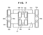
- Fig. 7 is a sectional view, seen from the positive direction along the Z-axis, of a surface that opposes the stages 51 and 54 and surface plate 55.
- the X stage 51 is supported by hydrostatic bearings 53b to be in non-contact with the surface plate 55
- the Y stage 54 is supported by hydrostatic bearings 53c and 53d to be in non-contact with the surface plate 55 and stationary guide 52.
- the X stage 51 and Y stage 54 are provided with magnet units 56a, 56b, and 56c which apply a preload force to stabilize the gaps of the hydrostatic bearings.
- Japanese Patent Laid-Open No. 2002-257138 discloses a mechanism in which a movable body is supported in a high vacuum by using a static pad, and a labyrinth portion having an exhaust groove is formed around the static pad.
- stage apparatus is sometimes used in a non-air atmosphere such as a vacuum atmosphere.
- a labyrinth partition is formed around a hydrostatic bearing so that air will not leak outside. Therefore, the attaching plate or stage becomes large, and its deformation amount also increases accordingly.
- degassing from a preload force biasing means which biases a preload force must also be taken into consideration.
- Embodiments of the present invention seek to provide a hydrodynamic bearing apparatus in which deformation caused in a constituent element such as a moving body or guide by a force applied by a hydrodynamic bearing and a preload force biased by a preload force biasing means is decreased.
- a hydrodynamic bearing apparatus for supporting a moving body with respect to a guide comprises a hydrodynamic bearing which is provided to the moving body and sprays a pressurized fluid to the guide, and preload force biasing means for generating a preload force between the moving body and guide, wherein the preload force biasing means is arranged dividedly around the hydrodynamic bearing.
- a hydrodynamic bearing apparatus for supporting a moving body with respect to a guide comprises a hydrodynamic bearing which is provided to the moving body and sprays a pressurized fluid to the guide, and preload force biasing means for generating a preload force between the moving body and guide, wherein the preload force biasing means includes a plurality of preload force biasing means arranged on each side of at least uni-axial direction on the hydrodynamic bearing symmetrically.
- the preload force biasing means is dividedly arranged around the hydrodynamic bearing, so that the plurality of preload force biasing means are arranged on each side of at least uni-axial direction on the hydrodynamic bearing symmetrically.
- the hydrodynamic bearing apparatus has a labyrinth partition to surround the hydrodynamic bearing, and the preload force biasing means is arranged inside the labyrinth partition.
- the preload force biasing means is desirably arranged inside one of the labyrinth partitions which is the closest to the hydrodynamic bearing.
- the guide may have a magnetic body portion, and the preload force biasing means may generate a magnetic force with respect to the guide, thus biasing a preload force.
- the preload force biasing means for example, a permanent magnet is enumerated.
- a height of the permanent magnet in a support direction is desirably equal to or smaller than a height of the labyrinth partition, provided to the moving body, in the support direction.
- the hydrodynamic bearing apparatus is desirably used in a stage apparatus, particularly in a stage apparatus that positions a substrate in an exposure apparatus.
- a “hydrodynamic bearing” means a portion which sprays a pressurized fluid, and can be replaced with, e.g., a hydrostatic pad.
- a "labyrinth partition” can be replaced with the step portion of a known labyrinth mechanism (e.g., see Japanese Patent Laid-Open No. 2002-257138).
- Apparatus is provided as set out in the claims.
- deformation occurring in a constituent member such as a moving body or guide by a force applied by a fluid bearing and a preload force generated by a preload force biasing means can be decreased.
- the influence of deformation can be effectively decreased in a uni-axial direction.
- deformation can be decreased further effectively.
- the preload force can be biased even in a vacuum atmosphere.
- a permanent magnet is used as a preload force biasing means, it can be machined, e.g., divided, easily.
- exhaust of fluid discharged from the hydrodynamic bearing can be prevented from being interfered to stabilize the bearing gaps.
- Fig. 1 is a schematic perspective view showing a wafer stage according to the first embodiment.
- a stage surface plate 11 made of a magnetic body is mounted at the central portion of a base surface plate 10.
- a pair of X surface plates 12b for placing thereon a pair of linear motor stators 12a which drive an X beam 12 in the X direction, and a pair of Y surface plates 13b for placing thereon a pair of linear motor stators 13a which drive a Y beam 13 in the Y direction are mounted around the stage surface plate 11.
- An X-Y slider 14 is arranged where the X and Y beams 12 and 13 intersect, and the respective beams 12 and 13 extend through the X-Y slider 14.
- the X and Y beams 12 and 13, and the X-Y slider 14 are supported at their extending portions to be in non-contact with each other (not shown), and the X-Y slider 14 is supported on the base surface plate 10 to be in non-contact with the base surface plate 10.
- the X-Y slider 14 can move in the X or Y direction.
- a fine-movement stage (not shown) which finely moves in six-axis directions is mounted on the X-Y slider 14.
- a wafer chuck which holds a wafer is arranged on the fine-movement stage.
- Y-attaching plates 13c are arranged at the two ends of the Y beam 13.
- Hydrostatic pneumatic bearings 131 (see Fig. 2) serving as hydrodynamic bearings are arranged on the bottom surfaces of the Y-attaching plates 13c.
- the hydrostatic pneumatic bearings 131 guide the Y-attaching plates 13c in the vertical direction (Z-axis direction) with respect to the stage surface plate 11.
- X-attaching plates 12c and 12d are arranged at the two ends of the X beam 12.
- Hydrostatic pneumatic bearings 121 at the bottoms of the X-attaching plates 12c and 12d guide the X-attaching plates 12c and 12d in the vertical direction (Z-axis direction) with respect to the stage surface plate 11.
- the X-attaching plate 12c is also guided by hydrostatic pneumatic bearings (not shown) in the horizontal direction (Y-axis direction) with respect to a stationary guide 15 attached to the stage surface plate 11.
- the X-Y slider 14 is guided by hydrostatic pressure pneumatic bearings 141 arranged on its bottom surface in the vertical direction (Z-axis direction) with respect to the stage surface plate 11.
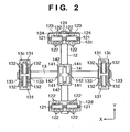
- Fig. 2 is a sectional view taken along the line A - A of Fig. 1
- Fig. 3 is a view seen from a direction of an arrow D of Fig. 1.
- the porous hydrostatic pneumatic bearings 121 are arranged on the lower surfaces of the X-attaching plates 12c and 12d, to levitate the X-attaching plates 12c and 12d with respect to the stage surface plate 11.
- the hydrostatic pneumatic bearings 131 and 141 are arranged on the lower surfaces of the Y-attaching plates 13c and X-Y slider 14, to levitate the Y-attaching plates 13c and X-Y slider 14 with respect to the stage surface plate 11.
- preload magnet units 122 serving as a preload force biasing means are arranged on the bottom surfaces of the X-attaching plates 12c and 12d dividedly around the hydrostatic pneumatic bearings.
- the plurality of preload magnet units 122 are arranged symmetrically (on each of the two sides or ends) on the hydrostatic pneumatic bearings 121 in a direction (Y-axis direction) perpendicular to the longitudinal direction.
- An attracting force acts between the preload magnet units 122 and the stage surface plate 11 serving as the magnetic body.
- the preload magnet units 122 are arranged dividedly in a plurality of groups so as to distribute the preload force (attracting force).
- the preload force biasing means can be divided easily as they can be machined easily, leading to an advantage in machining cost as well.
- preload magnet units 132 are provided to the hydrostatic pneumatic bearings 131. Note that the preload magnet units 132 are not arranged at the central portions in the longitudinal direction (Y direction) of the Y-attaching plates 13c. This is due to the following reason.
- X-guide magnet units 133 to guide in the X-axis direction are provided to the Y-attaching plates 13c. When the attracting forces of the X-guide magnet units 133 are considered, the deformation amount becomes smaller if no preload magnet units are arranged at the central portions in the longitudinal direction of the Y-attaching plates 13c.
- the X-guide magnet units 133 serve such that the Y-attaching plate 13c will not move beyond an end face 11a or groove side surface 11b of the stage surface plate 11.
- the Y beam 13 is provided with the X-guide magnet units 133 because it has no horizontal guides.
- the X-guide magnet units 133 also have the function of preload magnets.
- the Y-attaching plate 13c will be constrained excessively unless the perpendicularity of the two beams 12 and 13 is zero.
- the Y-attaching plate 13c is guided weakly by providing the X-guide magnet-units 133 as described above.
- the X beam 12 is guided in the Y-axis direction by the stationary guide 15 and hydrostatic pneumatic bearings 123.
- the X beam 12 is similarly provided with preload magnet units 124.
- Fig. 4 is a view showing the second embodiment.
- the major difference between the first and second embodiments is that the second embodiment can be used in a vacuum atmosphere.
- the overall perspective view of the second embodiment is not largely different from Fig. 1, and will be omitted accordingly.
- Fig. 4 a detailed description on portions that have the same functions as those of Fig. 2 will be omitted.
- Hydrostatic pneumatic bearings 221 are arranged on the bottom surface of each of X-attaching plates 22c and 22d, and preload magnet units 222 are arranged to surround the hydrostatic pneumatic bearings 221.
- a labyrinth partition 26 is formed around the preload magnet units 222.
- Hydrostatic pneumatic bearings 231 are arranged on the bottom surface of each Y-attaching plate 23c, and preload magnet units 232 are arranged to surround the hydrostatic pneumatic bearings 231.
- a labyrinth partition 27 is formed around the preload magnet units 232.
- the layout of the preload magnet units 222 and 232 with respect to the hydrostatic pneumatic bearings 221 and 231 is similar to that of the first embodiment. According to the characteristic feature of the second embodiment, the preload magnet units 222 and 232 are arranged inside the labyrinth partitions 26 and 27, respectively.
- Fig. 5 is a sectional view taken along the line F - F of Fig. 4, and shows the labyrinth partition 26 in detail.
- the labyrinth partition 26 includes a plurality of labyrinth partitions.
- the plurality of labyrinth partitions are arranged to define labyrinth pockets 261, 262, and 263. Air spraying from the hydrostatic pneumatic bearings 221 is exhausted from an exhaust portion (not shown) formed inside (the first-stage labyrinth pocket 261) a labyrinth partition closest to the bearings, and is discharged outside the chamber through an exhaust channel (not shown).
- Air that cannot be discharged completely with the first-stage labyrinth pocket 261 is exhausted from an exhaust portion formed in the second-stage labyrinth pocket 262.
- a small amount or air that cannot be exhausted completely with the second-stage labyrinth pocket 262 is exhausted from an exhaust portion formed in the third-stage labyrinth pocket 263.
- the preload magnet units 222 are arranged in the first-stage labyrinth pocket 261 dividedly around the hydrostatic pneumatic bearings 221.
- the plurality of preload magnet units 222 are arranged symmetrically (on each of the two sides or ends) on the hydrostatic pneumatic bearings 221 in a direction (Y-axis direction) perpendicular to the longitudinal direction.
- An attracting force acts between the preload magnet units 222 and the stage surface plate 11 serving as the magnetic body.
- the preload magnet units 222 are arranged dividedly in a plurality of groups so as to distribute the preload force (attracting force).
- the preload force biasing means can be divided easily as they can be machined easily, leading to an advantage in machining cost as well.
- the preload magnet units 222 are located in the first-stage labyrinth pocket 261, it is preferable in exhausting the out-gas of the magnets.
- the preload magnet units 222 are arranged such that their heights in the support direction (Z direction) are equal to or lower than that of the labyrinth partition 261, they can apply a preload force without interfering with the effect of the labyrinth partition. Then, the bearing gaps are stabilized.
- a preload In a vacuum atmosphere, a preload cannot be biased by gas attraction. Hence, it makes sense to bias a preload force by using a magnetic force in this manner.
- labyrinth partitions 28 are provided to four hydrostatic pneumatic bearings 241, respectively. If preload magnet units 242 are to be arranged around each hydrostatic pneumatic bearing 241, a large space will be required. Thus, the preload magnet units 242 are arranged outside the labyrinth partitions 28, respectively, as shown in Fig. 4. In this manner, it should be understood that, although design factors must be considered, the present invention exhibits its effect by practicing it locally for a portion where deformation is to be suppressed.
- the present invention can also be applied to a non-air atmosphere.
- the non-air atmosphere is an atmosphere filled with, e.g., helium or nitrogen.
- the actuating fluid for the hydrostatic pneumatic bearings is not limited to air but can be helium or nitrogen described above.
- Fig. 8 shows a semiconductor device manufacturing exposure apparatus which uses a stage apparatus similar to that described above as a wafer stage.
- This exposure apparatus is used for the manufacture of semiconductor devices such as a semiconductor integrated circuit, and devices such as a micromachine and thin-film magnetic head on which a fine pattern is formed.
- a semiconductor wafer W as a substrate is irradiated with exposure light (this term is a general term for visible light, ultraviolet light, EUV light, X-rays, an electron beam, a charged particle beam, and the like) as an exposure energy from a light source 161 through a reticle R as a master via a projection lens (this term is a general term for a dioptric lens, reflecting lens, cata-dioptric lens system, charged particle lens, and the like) 162 as a projection system, to form a desired pattern on the substrate.
- exposure light this term is a general term for visible light, ultraviolet light, EUV light, X-rays, an electron beam, a charged particle beam, and the like
- a projection lens this term is a general term for a dioptric lens, reflecting lens, cata-di
- an upper guide 152 and linear motor stators 172 are fixed on a surface plate 151.
- the linear motor stators 172 have multi-phase electromagnetic coils, and linear motor movable elements 171 have permanent magnet groups, in the same manner as that described above.
- the linear motor movable elements 171 are connected as movable portions 153 to movable guides 154 serving as a stage.
- the movable guides 154 are driven by linear motors M1 and are moved in a direction normal to the surface of the sheet of the drawing.
- the movable portions 153 are supported by hydrostatic bearings 155 with reference to the upper surface of the surface plate 151, and by a hydrostatic bearing 156 with reference to the side surface of the upper guide 152.
- a moving stage 157 serving as a stage arranged across the movable guides 154 is supported by hydrostatic bearings 158.
- the moving stage 157 is driven by a linear motor M2 similar to that described above.
- the moving stage 157 moves to the left or right on the surface of the sheet of the drawing with reference to the movable guides 154.
- the movement of the moving stage 157 is measured by using a mirror 159 fixed to the moving stage 157, and an interferometer 160.
- the wafer W as the substrate is held on a chuck mounted on the moving stage 157.
- the pattern of the reticle R as the master is reduced and transferred by the light source 161 and projection lens 162 onto the respective regions on the wafer W by the step & repeat scheme or step & scan scheme.
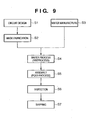
- Fig. 9 is a flow chart of an overall semiconductor device manufacturing process.
- step 1 circuit design
- step 2 mask fabrication
- a mask is fabricated based on the designed circuit pattern.
- step 3 wafer manufacture
- step 4 wafer process
- step 5 wafer process
- step 5 assembly
- step 6 inspections
- step 6 inspections
- a semiconductor device is completed with these processes, and is shipped in step 7.
- the wafer process of step 4 has the following steps: the oxidation step of oxidizing the surface of the wafer, the CVD step of forming an insulating film on the wafer surface, the electrode formation step of forming an electrode on the wafer by deposition, the ion implantation step of implanting ions into the wafer, the resist process step of applying a photosensitive agent to the wafer, the exposure step of transferring the circuit pattern to the wafer after the resist process step by the exposure apparatus described above, the developing step of developing the wafer exposed in the exposure step, the etching step of etching portions other than the resist image developed in the developing step, and the resist removing step of removing any unnecessary resist remaining after etching. By repeating these steps, a multilayered structure of circuit patterns is formed on the wafer.
Landscapes
- Engineering & Computer Science (AREA)
- General Engineering & Computer Science (AREA)
- Mechanical Engineering (AREA)
- Physics & Mathematics (AREA)
- General Physics & Mathematics (AREA)
- Environmental & Geological Engineering (AREA)
- Health & Medical Sciences (AREA)
- Epidemiology (AREA)
- Public Health (AREA)
- Exposure And Positioning Against Photoresist Photosensitive Materials (AREA)
- Magnetic Bearings And Hydrostatic Bearings (AREA)
- Container, Conveyance, Adherence, Positioning, Of Wafer (AREA)
- Exposure Of Semiconductors, Excluding Electron Or Ion Beam Exposure (AREA)
- Bearings For Parts Moving Linearly (AREA)
Applications Claiming Priority (2)
| Application Number | Priority Date | Filing Date | Title |
|---|---|---|---|
| JP2003356630A JP4455004B2 (ja) | 2003-10-16 | 2003-10-16 | 流体軸受装置およびそれを用いたステージ装置 |
| JP2003356630 | 2003-10-16 |
Publications (2)
| Publication Number | Publication Date |
|---|---|
| EP1524559A2 true EP1524559A2 (de) | 2005-04-20 |
| EP1524559A3 EP1524559A3 (de) | 2006-03-22 |
Family
ID=34373601
Family Applications (1)
| Application Number | Title | Priority Date | Filing Date |
|---|---|---|---|
| EP04256311A Ceased EP1524559A3 (de) | 2003-10-16 | 2004-10-13 | Hydrodynamische Lagervorrichtung und Trägerplattevorrichtung unter Verwendung derselben |
Country Status (3)
| Country | Link |
|---|---|
| US (1) | US7144160B2 (de) |
| EP (1) | EP1524559A3 (de) |
| JP (1) | JP4455004B2 (de) |
Cited By (1)
| Publication number | Priority date | Publication date | Assignee | Title |
|---|---|---|---|---|
| GB2555471A (en) * | 2016-10-31 | 2018-05-02 | Onesubsea Ip Uk Ltd | Magnetic preloading of bearings in rotating machines |
Families Citing this family (7)
| Publication number | Priority date | Publication date | Assignee | Title |
|---|---|---|---|---|
| KR100797725B1 (ko) * | 2006-03-15 | 2008-01-23 | 삼성전기주식회사 | 유체동압베어링의 유체충전장치 및 충전방법 |
| KR100807479B1 (ko) * | 2006-03-16 | 2008-02-25 | 삼성전기주식회사 | 유체동압베어링의 유체충전장치 및 충전방법 |
| US7978307B2 (en) * | 2006-05-04 | 2011-07-12 | Asml Netherlands B.V. | Gas bearing, and lithographic apparatus provided with such a bearing |
| JP2008078499A (ja) * | 2006-09-22 | 2008-04-03 | Canon Inc | 支持装置、露光装置及びデバイス製造方法 |
| JP5180555B2 (ja) * | 2007-10-04 | 2013-04-10 | キヤノン株式会社 | 位置決め装置、露光装置及びデバイス製造方法 |
| US8084896B2 (en) * | 2008-12-31 | 2011-12-27 | Electro Scientific Industries, Inc. | Monolithic stage positioning system and method |
| JP2011247405A (ja) * | 2009-07-30 | 2011-12-08 | Kyocera Corp | 案内装置 |
Family Cites Families (13)
| Publication number | Priority date | Publication date | Assignee | Title |
|---|---|---|---|---|
| FR2488353A1 (fr) * | 1980-08-07 | 1982-02-12 | Cermo | Dispositif hydrostatique de support |
| US4993696A (en) * | 1986-12-01 | 1991-02-19 | Canon Kabushiki Kaisha | Movable stage mechanism |
| US5040431A (en) * | 1988-01-22 | 1991-08-20 | Canon Kabushiki Kaisha | Movement guiding mechanism |
| US5098203A (en) * | 1991-03-11 | 1992-03-24 | Contraves Goerz Corporation | Bearing system |
| JPH06241230A (ja) | 1993-02-18 | 1994-08-30 | Canon Inc | 静圧軸受装置およびこれを用いた位置決めステージ |
| US5656942A (en) * | 1995-07-21 | 1997-08-12 | Electroglas, Inc. | Prober and tester with contact interface for integrated circuits-containing wafer held docked in a vertical plane |
| JP3729430B2 (ja) | 1997-03-13 | 2005-12-21 | キヤノン株式会社 | 静圧ステージ及び走査型露光装置 |
| US6128069A (en) * | 1997-03-13 | 2000-10-03 | Canon Kabushiki Kaisha | Stage mechanism for exposure apparatus |
| JP2001257143A (ja) * | 2000-03-09 | 2001-09-21 | Nikon Corp | ステージ装置及び露光装置、並びにデバイス製造方法 |
| US6467960B1 (en) * | 2000-08-18 | 2002-10-22 | Nikon Corporation | Air bearing linear guide for use in a vacuum |
| JP2002257138A (ja) | 2001-02-28 | 2002-09-11 | Canon Inc | 静圧流体軸受装置、およびこれを用いたステージ装置、露光装置ならびにデバイス製造方法 |
| JP2002349569A (ja) * | 2001-05-25 | 2002-12-04 | Canon Inc | 静圧軸受装置及びそれを用いたステージ装置 |
| US6756751B2 (en) * | 2002-02-15 | 2004-06-29 | Active Precision, Inc. | Multiple degree of freedom substrate manipulator |
-
2003
- 2003-10-16 JP JP2003356630A patent/JP4455004B2/ja not_active Expired - Fee Related
-
2004
- 2004-10-05 US US10/957,837 patent/US7144160B2/en not_active Expired - Fee Related
- 2004-10-13 EP EP04256311A patent/EP1524559A3/de not_active Ceased
Non-Patent Citations (1)
| Title |
|---|
| None |
Cited By (2)
| Publication number | Priority date | Publication date | Assignee | Title |
|---|---|---|---|---|
| GB2555471A (en) * | 2016-10-31 | 2018-05-02 | Onesubsea Ip Uk Ltd | Magnetic preloading of bearings in rotating machines |
| US10612593B2 (en) | 2016-10-31 | 2020-04-07 | Onesubsea Ip Uk Limited | Magnetic preloading of bearings in rotating machines |
Also Published As
| Publication number | Publication date |
|---|---|
| JP2005121134A (ja) | 2005-05-12 |
| US20050084187A1 (en) | 2005-04-21 |
| JP4455004B2 (ja) | 2010-04-21 |
| EP1524559A3 (de) | 2006-03-22 |
| US7144160B2 (en) | 2006-12-05 |
Similar Documents
| Publication | Publication Date | Title |
|---|---|---|
| US6421112B1 (en) | Movable support in a vacuum chamber and its application in lithographic projection apparatuses | |
| US10120288B2 (en) | Stage device, exposure apparatus, and method of manufacturing devices | |
| US6445440B1 (en) | Motion feed-through into a vacuum chamber and its application in lithographic projection apparatuses | |
| EP3866184B1 (de) | Trägersystem, belichtungsvorrichtung und zuführungsverfahren | |
| KR100855527B1 (ko) | 유지장치, 유지방법, 노광장치 및 디바이스 제조방법 | |
| US7280185B2 (en) | Stage system including fine-motion cable unit, exposure apparatus, and method of manufacturing device | |
| US7288859B2 (en) | Wafer stage operable in a vacuum environment | |
| US7817251B2 (en) | Supporting apparatus, exposure apparatus, and device manufacturing method | |
| US20060175993A1 (en) | Alignment apparatus, exposure apparatus, and device manufacturing method | |
| US6597433B1 (en) | Multi-stage drive arrangements and their application in lithographic projection apparatuses | |
| US6504599B2 (en) | Stage apparatus, exposure apparatus, and device manufacturing method | |
| EP1052551A2 (de) | Übertragung von Bewegung in eine Vakuumkammer hinein und deren Anwendung in lithographischen Projektionsapparaten | |
| US7144160B2 (en) | Hydrodynamic bearing apparatus and stage apparatus using the same | |
| US7224432B2 (en) | Stage device, exposure apparatus, and device manufacturing method | |
| EP1052549A2 (de) | Bewegbare Stützvorrichtung in einer Vakuumkammer und deren Anwendung in einem lithographischen Projektionsapparat | |
| EP1052550A2 (de) | Anordnungen zum Antrieb einer Mehrzahl Trägerplatten und deren Anwendung in lithographischen Projektionsapparaten | |
| US6648509B2 (en) | Friction-drive stage | |
| JP5058546B2 (ja) | 力発生装置およびこれを用いたステージ装置ならびに露光装置 | |
| EP1310828A1 (de) | Lithographischer Apparat und Verfahren zur Herstellung einer Vorrichtung | |
| HK1256632B (en) | Exposure apparatus, and method of manufacturing devices |
Legal Events
| Date | Code | Title | Description |
|---|---|---|---|
| PUAI | Public reference made under article 153(3) epc to a published international application that has entered the european phase |
Free format text: ORIGINAL CODE: 0009012 |
|
| AK | Designated contracting states |
Kind code of ref document: A2 Designated state(s): AT BE BG CH CY CZ DE DK EE ES FI FR GB GR HU IE IT LI LU MC NL PL PT RO SE SI SK TR |
|
| AX | Request for extension of the european patent |
Extension state: AL HR LT LV MK |
|
| PUAL | Search report despatched |
Free format text: ORIGINAL CODE: 0009013 |
|
| AK | Designated contracting states |
Kind code of ref document: A3 Designated state(s): AT BE BG CH CY CZ DE DK EE ES FI FR GB GR HU IE IT LI LU MC NL PL PT RO SE SI SK TR |
|
| AX | Request for extension of the european patent |
Extension state: AL HR LT LV MK |
|
| 17P | Request for examination filed |
Effective date: 20060922 |
|
| AKX | Designation fees paid |
Designated state(s): DE GB NL |
|
| 17Q | First examination report despatched |
Effective date: 20070117 |
|
| STAA | Information on the status of an ep patent application or granted ep patent |
Free format text: STATUS: THE APPLICATION HAS BEEN REFUSED |
|
| 18R | Application refused |
Effective date: 20101209 |