EP1524721A2 - Procédé pour émettre un signal électomagnétique et antenne associée - Google Patents
Procédé pour émettre un signal électomagnétique et antenne associée Download PDFInfo
- Publication number
- EP1524721A2 EP1524721A2 EP04292382A EP04292382A EP1524721A2 EP 1524721 A2 EP1524721 A2 EP 1524721A2 EP 04292382 A EP04292382 A EP 04292382A EP 04292382 A EP04292382 A EP 04292382A EP 1524721 A2 EP1524721 A2 EP 1524721A2
- Authority
- EP
- European Patent Office
- Prior art keywords
- laser
- antenna
- generator
- filamentation
- femto
- Prior art date
- Legal status (The legal status is an assumption and is not a legal conclusion. Google has not performed a legal analysis and makes no representation as to the accuracy of the status listed.)
- Granted
Links
Images
Classifications
-
- H—ELECTRICITY
- H01—ELECTRIC ELEMENTS
- H01Q—ANTENNAS, i.e. RADIO AERIALS
- H01Q1/00—Details of, or arrangements associated with, antennas
- H01Q1/36—Structural form of radiating elements, e.g. cone, spiral, umbrella; Particular materials used therewith
- H01Q1/364—Structural form of radiating elements, e.g. cone, spiral, umbrella; Particular materials used therewith using a particular conducting material, e.g. superconductor
- H01Q1/366—Structural form of radiating elements, e.g. cone, spiral, umbrella; Particular materials used therewith using a particular conducting material, e.g. superconductor using an ionized gas
-
- H—ELECTRICITY
- H01—ELECTRIC ELEMENTS
- H01Q—ANTENNAS, i.e. RADIO AERIALS
- H01Q1/00—Details of, or arrangements associated with, antennas
- H01Q1/27—Adaptation for use in or on movable bodies
- H01Q1/34—Adaptation for use in or on ships, submarines, buoys or torpedoes
-
- G—PHYSICS
- G02—OPTICS
- G02F—OPTICAL DEVICES OR ARRANGEMENTS FOR THE CONTROL OF LIGHT BY MODIFICATION OF THE OPTICAL PROPERTIES OF THE MEDIA OF THE ELEMENTS INVOLVED THEREIN; NON-LINEAR OPTICS; FREQUENCY-CHANGING OF LIGHT; OPTICAL LOGIC ELEMENTS; OPTICAL ANALOGUE/DIGITAL CONVERTERS
- G02F1/00—Devices or arrangements for the control of the intensity, colour, phase, polarisation or direction of light arriving from an independent light source, e.g. switching, gating or modulating; Non-linear optics
- G02F1/35—Non-linear optics
- G02F1/3511—Self-focusing or self-trapping of light; Light-induced birefringence; Induced optical Kerr-effect
Definitions
- the invention relates to the field of antennas and more particularly that plasma antennas able to operate over a very wide frequency band.
- the height of the quarter-type antennas wave should reach several hundred meters to several hundred kilometers, for example 750km to 100Hz, and their construction then becomes problematic. In addition, they can not be easily moved.
- This frequency domain is particularly useful in the context of communication with a submerged building such as a submarine.
- US Pat. No. 3,404,403 describes a plasma antenna comprising means for producing a laser beam, means capable of enabling the use of this laser in pulsed mode, means able to focus this laser beam to different points in order to ionize a column of air and means to couple a signal to the base of the air column.
- patent US6087993 which describes an antenna comprising a vertical ionizing ray generator, means for supplying the generator adapted to allow the production of a plasma column, the generator being suitable, in addition to producing a modulated current in the plasma.
- an electro-optical crystal is associated on the one hand with the laser beam and on the other hand with a generator of a frequency modulated signal. Thus the crystal modulates the phase or the amplitude of the laser, this modulation is reflected directly on the plasma column.
- the object of the invention is to provide an antenna easy to build, easy to move, not requiring a very large power supply and for which there is no phenomenon of non-linearity.
- an antenna comprising a generator of a laser radiation and means for coupling an electrical signal to this laser radiation, this antenna being characterized in that the generator (1) a laser radiation (2) is a femto-second laser.
- the generator comprises means able to pulsate the laser radiation.
- the generator comprises means capable of modifying the shape of the laser pulses and / or means capable of varying the power of the laser radiation.
- the coupling means comprise a coupling ring, preferably metal, disposed at the output of the generator.
- the coupling means comprise a acousto-optic modulator.
- the invention also relates to a method for transmitting a signal electromagnetic, characterized in that it comprises a step of generating a filamentation in air or in another gas with a femto-second laser, then to maintain this filamentation by generating laser pulses with said laser femto-second and to couple the electrical signal to the radiation emitted by the laser femtosecond.
- a method according to the invention comprises a step of controlling the length of the filamentation.
- control of the length of the filamentation is achieved by regulating the emission power of the laser.
- the reference value, for controlling the length of the filament corresponds to half or quarter of the wavelength of the carrier frequency of the electromagnetic signal.
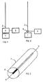
- FIG. 1 shows, schematically, an antenna according to the invention.
- This antenna comprises a generator 1 of a laser radiation 2, generation means 3 of an electrical signal, means 4 for coupling this electrical signal to said laser radiation 2 and this generator 1 of a radiation Laser 2 is a femto-second laser.
- This femto-second laser works, in this mode embodiment pulsed and in the air and it creates, as shown in Figure 2, not a column of plasma as in the case of the state of the art, but a filamentation that is to say a column 7 in which the refractive index is increasing from the outside inwards and that therefore generates ionization 6 only at the level of the axis of symmetry of the column so filamentous ionization 6 and not of the whole column 7, which considerably reduces the power to put into play for maintain ionization and eliminate problems of non-linearity.
- FIG. 3 shows more precisely the coupling means 4 according to a particular embodiment variant.
- the means for coupling the electrical signal with the laser are constituted by a metal ring 5, namely a ring of copper or any other material conductor, disposed just at the output of the femto-second laser 1 and in such a way that the laser radiation passes through the center of the circle formed by the ring 5.
- the means 3 for generating an electrical signal provide a signal to be transmitted within a signal generated at the carrier frequency.
- This electrical signal is generated by known means and this signal electrical power is transmitted to the coupling ring 5 which acts as an electrode on the laser filamentation by injecting into this filament the modulated signal which is thus emitted électramagnicallyment.
- the signal applied to the ring of coupling must have a maximum frequency compatible with the frequency sampling the ionized filament, ie the system uses filament relaxation to be able to emit.
- an antenna according to the invention is mobile and the emission is made discreetly with a yield close to one.
- no installation fixed infrastructure is needed for the program.
- No aircraft, balloon or other will only be needed to erect the transmitting antenna.
- the antenna is constituted by an ionized filament created by a femto-second laser directed upwards.
- the repetition frequency of this laser is in agreement with the minimum frequency sample of Shannon corresponding to the frequency VLF / LF ⁇ that we wants to emit.
- the power of the LASER is adjusted so that the length of the plasma is permanently equal to the tuning wavelength of the system, namely ⁇ , ⁇ / 4 or ⁇ / 2 according to the desired modes. For an agreement in ⁇ , / 2, the impedance seen at base of the antenna would be ohmic and would be worth 73 ⁇ , for an agreement in ⁇ / 4.
- the intangible side of the antenna makes it possible to get rid of most defects and difficulties related to the enormous size of the antennas to radiate energy at this frequency range. His agreement can be made instantaneous way by length adaptation and thus remove the devices agree that we must insert between the transmitters themselves and the antennas resignation. Thus the chord follows the modulation and thus allows modulations totally impossible to date. Debit and protection of information are greatly increased compared to the state of the art and weather resistance is out of proportion to what is known today.
- this antenna can also be used for the reception of a electromagnetic signal.
- an antenna according to the invention is not limited to a vertical filament and this filament can be generated in any direction.
Landscapes
- Lasers (AREA)
- Details Of Aerials (AREA)
- Variable-Direction Aerials And Aerial Arrays (AREA)
Abstract
Description
- La figure 1 présente un schéma général de l'invention.
- La figure 2 montre un schéma d'une variante de réalisation de l'invention.
Claims (9)
- Antenne comportant un générateur d'un rayonnement laser et des moyens de couplage d'un signal électrique à ce rayonnement laser, cette antenne étant caractérisée en ce que le générateur (1) d'un rayonnement laser (2) est un laser femto-seconde.
- Antenne selon la revendication 1, caractérisée en ce que le générateur comporte des moyens aptes à pulser le rayonnement laser.
- Antenne selon la revendication 2, caractérisée en ce que le générateur comporte des moyens aptes à modifier la forme des impulsions laser et/ou des moyens aptes à faire varier la puissance du rayonnement laser.
- Antenne selon l'une quelconque des revendications 1 à 3, caractérisée en ce que les moyens de couplage comportent un anneau de couplage, de préférence métallique, disposé en sortie du générateur.
- Antenne selon l'une quelconque des revendications 1 à 3, caractérisée en ce que les moyens de couplage comportent un modulateur acousto-optique.
- Procédé pour émettre un signal électromagnétique, caractérisé en ce qu'il comporte une étape consistant à générer une filamentation dans de l'air ou dans un autre gaz avec un laser femto-seconde, puis à maintenir cette filamentation en générant des impulsions laser avec ledit laser femto-seconde et à coupler le signal électrique au rayonnement émis par le laser femto-seconde.
- Procédé selon la revendication 6, caractérisé en ce qu'il comporte une étape de contrôle de la longueur de la filamentation.
- Procédé selon la revendication 7, caractérisé en ce que le contrôle de la longueur de la filamentation est réalisé par régulation de la puissance d'émission du laser.
- Procédé selon l'une quelconque des revendications 6 à 8, caractérisé en ce que la valeur de la consigne pour le contrôle de la longueur de la filamentation correspond à la demi ou au quart de la fréquence porteuse du signal électromagnétique.
Applications Claiming Priority (2)
| Application Number | Priority Date | Filing Date | Title |
|---|---|---|---|
| FR0312146 | 2003-10-17 | ||
| FR0312146A FR2863782B1 (fr) | 2003-10-17 | 2003-10-17 | Procede pour emettre un signal electromagnetique et antenne associee |
Publications (3)
| Publication Number | Publication Date |
|---|---|
| EP1524721A2 true EP1524721A2 (fr) | 2005-04-20 |
| EP1524721A3 EP1524721A3 (fr) | 2005-09-14 |
| EP1524721B1 EP1524721B1 (fr) | 2018-10-31 |
Family
ID=34355497
Family Applications (1)
| Application Number | Title | Priority Date | Filing Date |
|---|---|---|---|
| EP04292382.1A Expired - Lifetime EP1524721B1 (fr) | 2003-10-17 | 2004-10-07 | Procédé pour émettre un signal électromagnétique et antenne associée |
Country Status (5)
| Country | Link |
|---|---|
| US (1) | US7456791B2 (fr) |
| EP (1) | EP1524721B1 (fr) |
| CA (1) | CA2481891C (fr) |
| ES (1) | ES2703454T3 (fr) |
| FR (1) | FR2863782B1 (fr) |
Cited By (1)
| Publication number | Priority date | Publication date | Assignee | Title |
|---|---|---|---|---|
| FR2897207A1 (fr) * | 2006-02-07 | 2007-08-10 | Thales Sa | Dispositif de couplage entre une antenne a plasma et un generateur de signal de puissance |
Families Citing this family (6)
| Publication number | Priority date | Publication date | Assignee | Title |
|---|---|---|---|---|
| US8405562B2 (en) | 2010-03-09 | 2013-03-26 | Northrop Grumman Systems Corporation | Photoconductive semiconductor fiber antenna |
| US11024950B2 (en) | 2018-11-30 | 2021-06-01 | United States Of America As Represented By The Secretary Of The Navy | Wideband laser-induced plasma filament antenna with modulated conductivity |
| US12676680B2 (en) | 2022-12-16 | 2026-07-07 | The Boeing Company | Digital amplitude noise shift keying to communicate information |
| US12476710B2 (en) | 2022-12-16 | 2025-11-18 | The Boeing Company | Analog amplitude noise modulation to communicate information |
| US12401425B2 (en) | 2022-12-16 | 2025-08-26 | The Boeing Company | Radio frequency communications using laser optical breakdowns |
| US12407420B2 (en) | 2022-12-16 | 2025-09-02 | The Boeing Company | Pulse noise modulation to encode data |
Family Cites Families (13)
| Publication number | Priority date | Publication date | Assignee | Title |
|---|---|---|---|---|
| US5585913A (en) * | 1994-04-01 | 1996-12-17 | Imra America Inc. | Ultrashort pulsewidth laser ranging system employing a time gate producing an autocorrelation and method therefore |
| US5594456A (en) * | 1994-09-07 | 1997-01-14 | Patriot Scientific Corporation | Gas tube RF antenna |
| US6674970B1 (en) * | 1999-05-21 | 2004-01-06 | The United States Of America As Represented By The Secretary Of The Navy | Plasma antenna with two-fluid ionization current |
| US6046705A (en) * | 1999-05-21 | 2000-04-04 | The United States Of America As Represented By The Secretary Of The Navy | Standing wave plasma antenna with plasma reflector |
| US6087993A (en) * | 1999-05-21 | 2000-07-11 | The United States Of America As Represented By The Secretary Of The Navy | Plasma antenna with electro-optical modulator |
| US6369763B1 (en) * | 2000-04-05 | 2002-04-09 | Asi Technology Corporation | Reconfigurable plasma antenna |
| US7648100B2 (en) * | 2000-05-31 | 2010-01-19 | Kevin Kremeyer | Shock wave modification method and system |
| AUPR213900A0 (en) * | 2000-12-15 | 2001-01-25 | Luminis Pty Limited | A diagnostic apparatus |
| US6657594B2 (en) * | 2002-01-29 | 2003-12-02 | The United States Of America As Represented By The Secretary Of The Navy | Plasma antenna system and method |
| US6842146B2 (en) * | 2002-02-25 | 2005-01-11 | Markland Technologies, Inc. | Plasma filter antenna system |
| US6606063B1 (en) * | 2002-02-26 | 2003-08-12 | Bae Systems Information And Electronic Systems Integration Inc. | Radiation synthesizer feed configurations |
| US6650297B2 (en) * | 2002-04-10 | 2003-11-18 | The United States Of America As Represented By The Secretary Of The Navy | Laser driven plasma antenna utilizing laser modified maxwellian relaxation |
| US7063285B1 (en) * | 2003-11-04 | 2006-06-20 | Stratasys, Inc. | Cassette device for reliable filament delivery |
-
2003
- 2003-10-17 FR FR0312146A patent/FR2863782B1/fr not_active Expired - Fee Related
-
2004
- 2004-10-07 EP EP04292382.1A patent/EP1524721B1/fr not_active Expired - Lifetime
- 2004-10-07 ES ES04292382T patent/ES2703454T3/es not_active Expired - Lifetime
- 2004-10-15 CA CA2481891A patent/CA2481891C/fr not_active Expired - Fee Related
- 2004-10-15 US US10/964,665 patent/US7456791B2/en not_active Expired - Lifetime
Cited By (3)
| Publication number | Priority date | Publication date | Assignee | Title |
|---|---|---|---|---|
| FR2897207A1 (fr) * | 2006-02-07 | 2007-08-10 | Thales Sa | Dispositif de couplage entre une antenne a plasma et un generateur de signal de puissance |
| WO2007090850A1 (fr) * | 2006-02-07 | 2007-08-16 | Thales | Dispositif de couplage entre une antenne a plasma et un generateur de signal de puissance |
| US7965241B2 (en) | 2006-02-07 | 2011-06-21 | Thales | Device for coupling between a plasma antenna and a power signal generator |
Also Published As
| Publication number | Publication date |
|---|---|
| FR2863782B1 (fr) | 2007-01-05 |
| US7456791B2 (en) | 2008-11-25 |
| ES2703454T3 (es) | 2019-03-08 |
| CA2481891C (fr) | 2012-09-11 |
| FR2863782A1 (fr) | 2005-06-17 |
| US20050122272A1 (en) | 2005-06-09 |
| EP1524721B1 (fr) | 2018-10-31 |
| CA2481891A1 (fr) | 2005-04-17 |
| EP1524721A3 (fr) | 2005-09-14 |
Similar Documents
| Publication | Publication Date | Title |
|---|---|---|
| US6807375B2 (en) | Free-space optical communications with partially coherent beams | |
| US10120263B2 (en) | Low-duty-cycle continuous-wave photoconductive terahertz imaging and spectroscopy systems | |
| EP1524721B1 (fr) | Procédé pour émettre un signal électromagnétique et antenne associée | |
| EP1815492B1 (fr) | Dispositif generateur d'ondes hyperfrequences a cathode virtuelle oscillante | |
| CN106159641B (zh) | 携带轨道角动量的太赫兹波的发生装置及产生方法 | |
| Taillieu et al. | High-data-rate and resilient wireless links at the w-band enabled by all-metal spline horns | |
| Ducournau et al. | High‐definition television transmission at 600 GHz combining THz photonics hotspot and high‐sensitivity heterodyne receiver | |
| EP2660938A2 (fr) | Dispositif laser d'émission d'onde Térahertz à structure trouée | |
| CN106067592A (zh) | 一种收发一体的太赫兹天线及其制造方法和太赫兹测量系统 | |
| FR2985386A1 (fr) | Procede de calibrage d'un systeme d'emission d'ondes de forte puissance, procede d'emission par un tel systeme et systeme d'emission associe | |
| FR2974458A1 (fr) | Dispostif laser d'emission d'ondes dans le domaine des terahertz | |
| EP1982347B1 (fr) | Dispositif de couplage entre une antenne a plasma et un generateur de signal de puissance | |
| Wu et al. | Simultaneous generation of microwave, millimeter-wave, and terahertz photonic signal based on two-color semiconductor laser subject to single-beam optical injection | |
| Ettorre et al. | High speed and resilient wireless interconnects in the near field | |
| Morohashi et al. | Terahertz source with broad frequency tunability up to 3.8 THz using MZ-FCG for frequency reference in phase-locking of THz source devices | |
| CA3026312A1 (fr) | Module d'affinement spectral, dispositif a raie spectrale affinee et procede afferent | |
| Popov et al. | Lamp pumped LiSrAlF6: Cr laser with Bragg grating | |
| Khiabani et al. | THz photoconductive antennas in pulsed systems and CW systems | |
| JP3922463B2 (ja) | 赤外光放射装置および赤外光検出装置ならびに時系列変換パルス分光計測装置 | |
| Ebisawa et al. | Collimating metalens antenna with high directivity for integration into compact terahertz continuous-wave sources | |
| RU2690064C2 (ru) | Способ генерации электромагнитного излучения в широком диапазоне радиосвязи | |
| Kbashi et al. | Dual-Wavelength Fiber Laser for 5G and Lidar Applications | |
| EP0653853B1 (fr) | Système de communication en espace libre à détection hétérodyne grand champ | |
| Lepeshov et al. | Novel optimized hybrid terahertz photoconductive antennas | |
| FR2870386A1 (fr) | Emetteur et detecteur de rayonnement electromagnetique. |
Legal Events
| Date | Code | Title | Description |
|---|---|---|---|
| PUAI | Public reference made under article 153(3) epc to a published international application that has entered the european phase |
Free format text: ORIGINAL CODE: 0009012 |
|
| AK | Designated contracting states |
Kind code of ref document: A2 Designated state(s): AT BE BG CH CY CZ DE DK EE ES FI FR GB GR HU IE IT LI LU MC NL PL PT RO SE SI SK TR |
|
| AX | Request for extension of the european patent |
Extension state: AL HR LT LV MK |
|
| PUAL | Search report despatched |
Free format text: ORIGINAL CODE: 0009013 |
|
| AK | Designated contracting states |
Kind code of ref document: A3 Designated state(s): AT BE BG CH CY CZ DE DK EE ES FI FR GB GR HU IE IT LI LU MC NL PL PT RO SE SI SK TR |
|
| AX | Request for extension of the european patent |
Extension state: AL HR LT LV MK |
|
| 17P | Request for examination filed |
Effective date: 20051117 |
|
| AKX | Designation fees paid |
Designated state(s): AT BE BG CH CY CZ DE DK EE ES FI FR GB GR HU IE IT LI LU MC NL PL PT RO SE SI SK TR |
|
| 17Q | First examination report despatched |
Effective date: 20060706 |
|
| RAP1 | Party data changed (applicant data changed or rights of an application transferred) |
Owner name: ETAT FRANCAIS REPRESENTE PAR LE DELEGUE GENERAL PO |
|
| RIC1 | Information provided on ipc code assigned before grant |
Ipc: G02F 1/35 19740701ALI20180301BHEP Ipc: H01Q 1/36 19680901AFI20180301BHEP Ipc: H01Q 1/34 19680901ALI20180301BHEP |
|
| GRAP | Despatch of communication of intention to grant a patent |
Free format text: ORIGINAL CODE: EPIDOSNIGR1 |
|
| STAA | Information on the status of an ep patent application or granted ep patent |
Free format text: STATUS: GRANT OF PATENT IS INTENDED |
|
| INTG | Intention to grant announced |
Effective date: 20180412 |
|
| GRAS | Grant fee paid |
Free format text: ORIGINAL CODE: EPIDOSNIGR3 |
|
| GRAA | (expected) grant |
Free format text: ORIGINAL CODE: 0009210 |
|
| STAA | Information on the status of an ep patent application or granted ep patent |
Free format text: STATUS: THE PATENT HAS BEEN GRANTED |
|
| AK | Designated contracting states |
Kind code of ref document: B1 Designated state(s): AT BE BG CH CY CZ DE DK EE ES FI FR GB GR HU IE IT LI LU MC NL PL PT RO SE SI SK TR |
|
| REG | Reference to a national code |
Ref country code: CH Ref legal event code: EP Ref country code: GB Ref legal event code: FG4D Free format text: NOT ENGLISH |
|
| REG | Reference to a national code |
Ref country code: AT Ref legal event code: REF Ref document number: 1060517 Country of ref document: AT Kind code of ref document: T Effective date: 20181115 |
|
| REG | Reference to a national code |
Ref country code: DE Ref legal event code: R096 Ref document number: 602004053347 Country of ref document: DE |
|
| REG | Reference to a national code |
Ref country code: IE Ref legal event code: FG4D Free format text: LANGUAGE OF EP DOCUMENT: FRENCH |
|
| REG | Reference to a national code |
Ref country code: CH Ref legal event code: PK Free format text: RECTIFICATIONS |
|
| RIC2 | Information provided on ipc code assigned after grant |
Ipc: G02F 1/35 20060101ALI20180301BHEP Ipc: H01Q 1/34 20060101ALI20180301BHEP Ipc: H01Q 1/36 20060101AFI20180301BHEP |
|
| REG | Reference to a national code |
Ref country code: SE Ref legal event code: TRGR |
|
| REG | Reference to a national code |
Ref country code: NL Ref legal event code: MP Effective date: 20181031 |
|
| REG | Reference to a national code |
Ref country code: ES Ref legal event code: FG2A Ref document number: 2703454 Country of ref document: ES Kind code of ref document: T3 Effective date: 20190308 |
|
| PG25 | Lapsed in a contracting state [announced via postgrant information from national office to epo] |
Ref country code: PL Free format text: LAPSE BECAUSE OF FAILURE TO SUBMIT A TRANSLATION OF THE DESCRIPTION OR TO PAY THE FEE WITHIN THE PRESCRIBED TIME-LIMIT Effective date: 20181031 Ref country code: BG Free format text: LAPSE BECAUSE OF FAILURE TO SUBMIT A TRANSLATION OF THE DESCRIPTION OR TO PAY THE FEE WITHIN THE PRESCRIBED TIME-LIMIT Effective date: 20190131 Ref country code: FI Free format text: LAPSE BECAUSE OF FAILURE TO SUBMIT A TRANSLATION OF THE DESCRIPTION OR TO PAY THE FEE WITHIN THE PRESCRIBED TIME-LIMIT Effective date: 20181031 |
|
| PG25 | Lapsed in a contracting state [announced via postgrant information from national office to epo] |
Ref country code: PT Free format text: LAPSE BECAUSE OF FAILURE TO SUBMIT A TRANSLATION OF THE DESCRIPTION OR TO PAY THE FEE WITHIN THE PRESCRIBED TIME-LIMIT Effective date: 20190301 Ref country code: GR Free format text: LAPSE BECAUSE OF FAILURE TO SUBMIT A TRANSLATION OF THE DESCRIPTION OR TO PAY THE FEE WITHIN THE PRESCRIBED TIME-LIMIT Effective date: 20190201 Ref country code: NL Free format text: LAPSE BECAUSE OF FAILURE TO SUBMIT A TRANSLATION OF THE DESCRIPTION OR TO PAY THE FEE WITHIN THE PRESCRIBED TIME-LIMIT Effective date: 20181031 |
|
| PG25 | Lapsed in a contracting state [announced via postgrant information from national office to epo] |
Ref country code: DK Free format text: LAPSE BECAUSE OF FAILURE TO SUBMIT A TRANSLATION OF THE DESCRIPTION OR TO PAY THE FEE WITHIN THE PRESCRIBED TIME-LIMIT Effective date: 20181031 Ref country code: CZ Free format text: LAPSE BECAUSE OF FAILURE TO SUBMIT A TRANSLATION OF THE DESCRIPTION OR TO PAY THE FEE WITHIN THE PRESCRIBED TIME-LIMIT Effective date: 20181031 |
|
| REG | Reference to a national code |
Ref country code: DE Ref legal event code: R097 Ref document number: 602004053347 Country of ref document: DE |
|
| PG25 | Lapsed in a contracting state [announced via postgrant information from national office to epo] |
Ref country code: RO Free format text: LAPSE BECAUSE OF FAILURE TO SUBMIT A TRANSLATION OF THE DESCRIPTION OR TO PAY THE FEE WITHIN THE PRESCRIBED TIME-LIMIT Effective date: 20181031 Ref country code: EE Free format text: LAPSE BECAUSE OF FAILURE TO SUBMIT A TRANSLATION OF THE DESCRIPTION OR TO PAY THE FEE WITHIN THE PRESCRIBED TIME-LIMIT Effective date: 20181031 Ref country code: SK Free format text: LAPSE BECAUSE OF FAILURE TO SUBMIT A TRANSLATION OF THE DESCRIPTION OR TO PAY THE FEE WITHIN THE PRESCRIBED TIME-LIMIT Effective date: 20181031 |
|
| PLBE | No opposition filed within time limit |
Free format text: ORIGINAL CODE: 0009261 |
|
| STAA | Information on the status of an ep patent application or granted ep patent |
Free format text: STATUS: NO OPPOSITION FILED WITHIN TIME LIMIT |
|
| 26N | No opposition filed |
Effective date: 20190801 |
|
| PG25 | Lapsed in a contracting state [announced via postgrant information from national office to epo] |
Ref country code: SI Free format text: LAPSE BECAUSE OF FAILURE TO SUBMIT A TRANSLATION OF THE DESCRIPTION OR TO PAY THE FEE WITHIN THE PRESCRIBED TIME-LIMIT Effective date: 20181031 |
|
| PG25 | Lapsed in a contracting state [announced via postgrant information from national office to epo] |
Ref country code: TR Free format text: LAPSE BECAUSE OF FAILURE TO SUBMIT A TRANSLATION OF THE DESCRIPTION OR TO PAY THE FEE WITHIN THE PRESCRIBED TIME-LIMIT Effective date: 20181031 |
|
| PG25 | Lapsed in a contracting state [announced via postgrant information from national office to epo] |
Ref country code: MC Free format text: LAPSE BECAUSE OF FAILURE TO SUBMIT A TRANSLATION OF THE DESCRIPTION OR TO PAY THE FEE WITHIN THE PRESCRIBED TIME-LIMIT Effective date: 20181031 |
|
| PGFP | Annual fee paid to national office [announced via postgrant information from national office to epo] |
Ref country code: FR Payment date: 20200123 Year of fee payment: 17 |
|
| PG25 | Lapsed in a contracting state [announced via postgrant information from national office to epo] |
Ref country code: IE Free format text: LAPSE BECAUSE OF NON-PAYMENT OF DUE FEES Effective date: 20191007 |
|
| REG | Reference to a national code |
Ref country code: AT Ref legal event code: UEP Ref document number: 1060517 Country of ref document: AT Kind code of ref document: T Effective date: 20181031 |
|
| PGFP | Annual fee paid to national office [announced via postgrant information from national office to epo] |
Ref country code: LU Payment date: 20201022 Year of fee payment: 17 |
|
| PGFP | Annual fee paid to national office [announced via postgrant information from national office to epo] |
Ref country code: DE Payment date: 20201023 Year of fee payment: 17 Ref country code: IT Payment date: 20201023 Year of fee payment: 17 Ref country code: ES Payment date: 20201104 Year of fee payment: 17 Ref country code: GB Payment date: 20201021 Year of fee payment: 17 Ref country code: AT Payment date: 20201022 Year of fee payment: 17 Ref country code: CH Payment date: 20201027 Year of fee payment: 17 Ref country code: SE Payment date: 20201023 Year of fee payment: 17 |
|
| PGFP | Annual fee paid to national office [announced via postgrant information from national office to epo] |
Ref country code: BE Payment date: 20201023 Year of fee payment: 17 |
|
| PG25 | Lapsed in a contracting state [announced via postgrant information from national office to epo] |
Ref country code: CY Free format text: LAPSE BECAUSE OF FAILURE TO SUBMIT A TRANSLATION OF THE DESCRIPTION OR TO PAY THE FEE WITHIN THE PRESCRIBED TIME-LIMIT Effective date: 20181031 |
|
| PG25 | Lapsed in a contracting state [announced via postgrant information from national office to epo] |
Ref country code: HU Free format text: LAPSE BECAUSE OF FAILURE TO SUBMIT A TRANSLATION OF THE DESCRIPTION OR TO PAY THE FEE WITHIN THE PRESCRIBED TIME-LIMIT; INVALID AB INITIO Effective date: 20041007 |
|
| REG | Reference to a national code |
Ref country code: DE Ref legal event code: R119 Ref document number: 602004053347 Country of ref document: DE |
|
| REG | Reference to a national code |
Ref country code: CH Ref legal event code: PL Ref country code: SE Ref legal event code: EUG |
|
| REG | Reference to a national code |
Ref country code: AT Ref legal event code: MM01 Ref document number: 1060517 Country of ref document: AT Kind code of ref document: T Effective date: 20211007 |
|
| REG | Reference to a national code |
Ref country code: BE Ref legal event code: MM Effective date: 20211031 |
|
| GBPC | Gb: european patent ceased through non-payment of renewal fee |
Effective date: 20211007 |
|
| PG25 | Lapsed in a contracting state [announced via postgrant information from national office to epo] |
Ref country code: SE Free format text: LAPSE BECAUSE OF NON-PAYMENT OF DUE FEES Effective date: 20211008 Ref country code: LU Free format text: LAPSE BECAUSE OF NON-PAYMENT OF DUE FEES Effective date: 20211007 Ref country code: GB Free format text: LAPSE BECAUSE OF NON-PAYMENT OF DUE FEES Effective date: 20211007 Ref country code: DE Free format text: LAPSE BECAUSE OF NON-PAYMENT OF DUE FEES Effective date: 20220503 Ref country code: BE Free format text: LAPSE BECAUSE OF NON-PAYMENT OF DUE FEES Effective date: 20211031 |
|
| PG25 | Lapsed in a contracting state [announced via postgrant information from national office to epo] |
Ref country code: LI Free format text: LAPSE BECAUSE OF NON-PAYMENT OF DUE FEES Effective date: 20211031 Ref country code: CH Free format text: LAPSE BECAUSE OF NON-PAYMENT OF DUE FEES Effective date: 20211031 Ref country code: AT Free format text: LAPSE BECAUSE OF NON-PAYMENT OF DUE FEES Effective date: 20211007 |
|
| PG25 | Lapsed in a contracting state [announced via postgrant information from national office to epo] |
Ref country code: FR Free format text: LAPSE BECAUSE OF NON-PAYMENT OF DUE FEES Effective date: 20211031 |
|
| PG25 | Lapsed in a contracting state [announced via postgrant information from national office to epo] |
Ref country code: IT Free format text: LAPSE BECAUSE OF NON-PAYMENT OF DUE FEES Effective date: 20211007 |
|
| REG | Reference to a national code |
Ref country code: ES Ref legal event code: FD2A Effective date: 20221128 |
|
| PG25 | Lapsed in a contracting state [announced via postgrant information from national office to epo] |
Ref country code: ES Free format text: LAPSE BECAUSE OF NON-PAYMENT OF DUE FEES Effective date: 20211008 |