EP1524724A1 - Anschlussklemme zum Aufsetzen auf ein Trägerelement - Google Patents
Anschlussklemme zum Aufsetzen auf ein Trägerelement Download PDFInfo
- Publication number
- EP1524724A1 EP1524724A1 EP04021507A EP04021507A EP1524724A1 EP 1524724 A1 EP1524724 A1 EP 1524724A1 EP 04021507 A EP04021507 A EP 04021507A EP 04021507 A EP04021507 A EP 04021507A EP 1524724 A1 EP1524724 A1 EP 1524724A1
- Authority
- EP
- European Patent Office
- Prior art keywords
- housing
- conductor
- terminal according
- busbar
- terminal
- Prior art date
- Legal status (The legal status is an assumption and is not a legal conclusion. Google has not performed a legal analysis and makes no representation as to the accuracy of the status listed.)
- Granted
Links
- 239000004020 conductor Substances 0.000 claims abstract description 39
- 238000003780 insertion Methods 0.000 claims description 22
- 230000037431 insertion Effects 0.000 claims description 22
- 241000722921 Tulipa gesneriana Species 0.000 claims description 8
- 238000005452 bending Methods 0.000 claims description 5
- 238000010276 construction Methods 0.000 claims description 3
- 238000005516 engineering process Methods 0.000 claims description 2
- 238000004080 punching Methods 0.000 claims description 2
- 239000002184 metal Substances 0.000 description 3
- 239000002360 explosive Substances 0.000 description 2
- 238000009434 installation Methods 0.000 description 1
- 238000000034 method Methods 0.000 description 1
- 238000005192 partition Methods 0.000 description 1
- 239000000523 sample Substances 0.000 description 1
Images


Classifications
-
- H—ELECTRICITY
- H01—ELECTRIC ELEMENTS
- H01R—ELECTRICALLY-CONDUCTIVE CONNECTIONS; STRUCTURAL ASSOCIATIONS OF A PLURALITY OF MUTUALLY-INSULATED ELECTRICAL CONNECTING ELEMENTS; COUPLING DEVICES; CURRENT COLLECTORS
- H01R4/00—Electrically-conductive connections between two or more conductive members in direct contact, i.e. touching one another; Means for effecting or maintaining such contact; Electrically-conductive connections having two or more spaced connecting locations for conductors and using contact members penetrating insulation
- H01R4/10—Electrically-conductive connections between two or more conductive members in direct contact, i.e. touching one another; Means for effecting or maintaining such contact; Electrically-conductive connections having two or more spaced connecting locations for conductors and using contact members penetrating insulation effected solely by twisting, wrapping, bending, crimping, or other permanent deformation
- H01R4/16—Electrically-conductive connections between two or more conductive members in direct contact, i.e. touching one another; Means for effecting or maintaining such contact; Electrically-conductive connections having two or more spaced connecting locations for conductors and using contact members penetrating insulation effected solely by twisting, wrapping, bending, crimping, or other permanent deformation by bending
-
- H—ELECTRICITY
- H01—ELECTRIC ELEMENTS
- H01R—ELECTRICALLY-CONDUCTIVE CONNECTIONS; STRUCTURAL ASSOCIATIONS OF A PLURALITY OF MUTUALLY-INSULATED ELECTRICAL CONNECTING ELEMENTS; COUPLING DEVICES; CURRENT COLLECTORS
- H01R4/00—Electrically-conductive connections between two or more conductive members in direct contact, i.e. touching one another; Means for effecting or maintaining such contact; Electrically-conductive connections having two or more spaced connecting locations for conductors and using contact members penetrating insulation
- H01R4/28—Clamped connections, spring connections
- H01R4/48—Clamped connections, spring connections utilising a spring, clip, or other resilient member
- H01R4/4809—Clamped connections, spring connections utilising a spring, clip, or other resilient member using a leaf spring to bias the conductor toward the busbar
- H01R4/48185—Clamped connections, spring connections utilising a spring, clip, or other resilient member using a leaf spring to bias the conductor toward the busbar adapted for axial insertion of a wire end
- H01R4/4819—Clamped connections, spring connections utilising a spring, clip, or other resilient member using a leaf spring to bias the conductor toward the busbar adapted for axial insertion of a wire end the spring shape allowing insertion of the conductor end when the spring is unbiased
- H01R4/4823—Multiblade spring
-
- H—ELECTRICITY
- H01—ELECTRIC ELEMENTS
- H01R—ELECTRICALLY-CONDUCTIVE CONNECTIONS; STRUCTURAL ASSOCIATIONS OF A PLURALITY OF MUTUALLY-INSULATED ELECTRICAL CONNECTING ELEMENTS; COUPLING DEVICES; CURRENT COLLECTORS
- H01R4/00—Electrically-conductive connections between two or more conductive members in direct contact, i.e. touching one another; Means for effecting or maintaining such contact; Electrically-conductive connections having two or more spaced connecting locations for conductors and using contact members penetrating insulation
- H01R4/28—Clamped connections, spring connections
- H01R4/48—Clamped connections, spring connections utilising a spring, clip, or other resilient member
- H01R4/4809—Clamped connections, spring connections utilising a spring, clip, or other resilient member using a leaf spring to bias the conductor toward the busbar
- H01R4/484—Spring housing details
-
- H—ELECTRICITY
- H01—ELECTRIC ELEMENTS
- H01R—ELECTRICALLY-CONDUCTIVE CONNECTIONS; STRUCTURAL ASSOCIATIONS OF A PLURALITY OF MUTUALLY-INSULATED ELECTRICAL CONNECTING ELEMENTS; COUPLING DEVICES; CURRENT COLLECTORS
- H01R4/00—Electrically-conductive connections between two or more conductive members in direct contact, i.e. touching one another; Means for effecting or maintaining such contact; Electrically-conductive connections having two or more spaced connecting locations for conductors and using contact members penetrating insulation
- H01R4/28—Clamped connections, spring connections
- H01R4/48—Clamped connections, spring connections utilising a spring, clip, or other resilient member
- H01R4/4809—Clamped connections, spring connections utilising a spring, clip, or other resilient member using a leaf spring to bias the conductor toward the busbar
- H01R4/4846—Busbar details
-
- H—ELECTRICITY
- H01—ELECTRIC ELEMENTS
- H01R—ELECTRICALLY-CONDUCTIVE CONNECTIONS; STRUCTURAL ASSOCIATIONS OF A PLURALITY OF MUTUALLY-INSULATED ELECTRICAL CONNECTING ELEMENTS; COUPLING DEVICES; CURRENT COLLECTORS
- H01R9/00—Structural associations of a plurality of mutually-insulated electrical connecting elements, e.g. terminal strips or terminal blocks; Terminals or binding posts mounted upon a base or in a case; Bases therefor
- H01R9/22—Bases, e.g. strip, block, panel
- H01R9/24—Terminal blocks
- H01R9/26—Clip-on terminal blocks for side-by-side rail- or strip-mounting
Definitions
- the invention relates to a terminal with a housing, in particular for Latching onto a carrier element, wherein in the housing at least one or more Connection devices for connecting in each case at least one conductor is used or are.
- the invention solves this problem by the subject matter of claim 1. Thereafter comprises at least one of the terminal devices on a busbar, which with a Through hole for inserting the one conductor is provided, wherein a Clamping spring can be pushed onto the busbar so that they pass through the Through hole stuck conductor clamped on the busbar bending.
- a drawbar connection is selected as the further connection device, it has this expedient the tie bar with the busbar and the clamping screw to connect of the first conductor of larger diameter, being connected to the busbar of the drawbar connects a free busbar leg, with the through hole for inserting the second, pre-assembled conductor of smaller diameter is provided.
- the clamping spring is tulip-like and by means of Webs of the carrier element, which engage in the assembly in slots of the housing, pushed onto the busbar during assembly on the support element.
- the further conductor may be, for example, a very thin data line act on the support element, which is inserted only during assembly in the through hole becomes. Then the housing is placed on the support element and locked there, wherein the clamping spring clamps the thin data line to the carrier element.
- the further connection device can then be a conductor with a much larger Diameter - e.g. from a home installation - to be introduced. It is thus not only in a simple way possible, the very thin conductor easily to yourself but it is also possible in the simplest way, the very thin conductor to connect with a much thicker conductor.
- the construction of the terminal is structurally simple and the assembly without special tools in the manner of a setting placement of the support element to simple Automated way possible.
- the housing has a cost-effective two-part construction an upper housing part and a lower housing part, which can be locked together are.
- the upper housing part is on its side facing the housing lower part open and has at least one or more intermediate walls, which the space in the housing base depending on the number of connection devices - e.g. ever according to interpretation 2, 3 or more - subdivide into a corresponding number of chambers.
- one of the connection devices is in each of the chambers as a passage connection used. Both the number of chambers and the directions of connection It can thus be used to realize different numbers of connections in a simple way be varied.
- the busbar is bent in a U-shape in its upper region, wherein the one of the two longitudinal legs of the U engages in the clamping yoke and wherein at the at the other of the two longitudinal legs of the legs with the through hole of the U bent by 90 ° outwards.
- one of the side walls of the upper housing part depending Wegbügel in Compact design each have an insertion opening for inserting a conductor in the drawbar and another insertion opening for inserting a conductor into the through hole educated.
- the housing and fixing are further in easier Way projecting lugs provided, which to the rear grip of a corresponding Undercut serve in a receiving slot of the support element, wherein a rear grip on the opposite side of the housing by means of a latching hook takes place on the support member which is latched to the housing when the housing pivots after insertion of the nose in the undercuts on the support element.
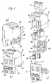
- the feed-through terminal according to FIGS. 1a-c has a housing 1 with an upper housing part 2 and a lower housing part 3, which together at a plurality of locking lugs 27 and latching recesses 28 in which engage the locking lugs 27, locked are further, wherein webs 29 of the upper housing part 2 in the lower housing part. 3 intervention.
- the upper housing part 2 is open at its side facing the lower housing part 3 designed. It has at least one or more intermediate walls 4, which the Space in the upper housing part 2 depending on the number of connection devices or depending on Number of through ports (e.g., two or three) into a corresponding number of chambers 5, 6 divide.
- each chamber 5, 6 is one of the connection means as a passage connection used.
- each connection device 34 comprises a clamping yoke 7 with a clamping screw 8, wherein an opening 9 is provided on the upper side of the upper housing part per clamping yoke 7 which is for inserting a screwdriver for actuating the Clamping screw 8 of the drawbar 7 is used.
- This leg 13 has as another terminal contact of the connection device 34th a through hole 14 for inserting a very thin conductor 20 (Figure 2), wherein the leg 13 in its mounting position in a tulip-like clamping spring 15th engages (section of Fig. 3b).
- the base leg 26 of the U is further closed integrally (for example in stamping / bending technique) here by way of example in each case a tulip contact 16, whose insertion opening 17 is adjacent to the clamping yoke in the housing, in each case adjacent to the opening.
- a further opening 30 (Fig. 1a) is provided is that which serves to insert another conductor in the tulip contact 16.
- each tension bow 7 On one of the side walls of the upper housing part 2 is further each tension bow 7 an insertion 18 for introducing a conductor with a larger diameter in the drawbar 7 trained.
- connection device 34 thus has the embodiment of FIG. 1 to 3 three connection contacts for conductors (and / or plugs), which are conductive with each other be connected: one of the clamping yoke 7, one of the tulip contacts 16 (insertion direction perpendicular to the drawbar) and the through hole 14 with the Clamping spring 15.
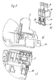
- the one end of the thin conductor 20th inserted, with the U-shaped clamping spring 15 on the leg 14 in this Region when inserting also bent into a U-shape within the clamping spring 15 and thus fixed (Fig. 2a, Fig. 3).
- the conductor 20 stands out of the insertion opening 19 with a free end in front, with an electronics on the support element can be connected.
- a carrier element 24 (such as a device housing or a circuit board receiving housing) serve on one side of the housing 1 two laterally projecting lugs 21, which for the rear grip of a corresponding undercut 22 serve in a receiving shaft 23 of the support member 24.
- a rear grip on the opposite side is at a shoulder 35th on the housing next to two projecting insertion funnel 25 at the insertion opening 19th realized to the through hole 14, which has a latching hook 31 on the carrier element 24th engage behind when the housing 1 after insertion of the nose 21 in the undercuts 23 is pivoted onto the carrier element 24 (FIG. 2b).
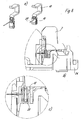
- webs 32 on the carrier element 24 engage in slots 33 of the housing lower part 3 a, which are designed and arranged so that they the clamping springs 15 from postpone a pre-assembly on the legs 13 of the busbar 10, wherein they use the very thin conductor 20 - e.g. 0.3mm - bend in a simple manner accordingly and preassembled in a secure manner by clamping (FIGS. 2 c, 3 a - c).
- FIGS. 4 to 6 differ from those of FIGS. 1 to 3 in that no tulip contacts to the base legs 26 of the U-shaped Busbars are molded. This reduces the number of connection contacts each chamber by one, but in many applications meets the requirements.
- the upper housing part 2 is shown in FIG. 4 - 6 in the area of each chamber provided with an opening 36 to which the here in the breakthrough projecting busbars 10 with a probe or the like. Contactable are.
Landscapes
- Connections Arranged To Contact A Plurality Of Conductors (AREA)
- Details Of Connecting Devices For Male And Female Coupling (AREA)
- Connection Or Junction Boxes (AREA)
- Wire Bonding (AREA)
- Lead Frames For Integrated Circuits (AREA)
- Installation Of Bus-Bars (AREA)
Abstract
Description
- Fig. 1a, b
- zwei perspektivische Ansichten einer ersten Durchgangsklemme in zwei verschiedenen Richtungen,
- Fig. 1c
- eine Sprengansicht der Durchgangsklemme aus Fig. 1a,b; und
- Fig. 2a-c
- eine Darstellung der Metallteile einer der Anschlusseinrichtungen der Durchgangsklemme sowie zwei Darstellungen der Durchgangsklemme, welche die Montage der Metallteile und die der Durchgangsklemme an einem Trägerelement veranschaulichen;
- Fig. 3a-c
- eine Darstellung einer der Anschlusseinrichtungen der Durchgangsklemme sowie zwei Schnittdarstellungen der Durchgangsklemme im montierten Zustand
- Fig.4a, b
- zwei perspektivische Ansichten einer zweiten Durchgangsklemme in zwei verschiedenen Richtungen,
- Fig. 4c
- eine Sprengansicht der Durchgangsklemme aus Fig. 4a,b;
- Fig. 5a-c
- eine Darstellung der Metallteile der Klemme aus Fig. 4 nach Art der Darstellung der Fig. 2; und
- Fig. 6a-c
- eine Darstellung einer der Anschlusseinrichtungen der Durchgangsklemme aus Fig. 4 und 5 sowie zwei Schnittdarstellungen der Durchgangsklemme im montierten Zustand.
- Gehäuse
- 1
- Gehäuseoberteil
- 2
- Gehäuseunterteil
- 3
- Zwischenwände
- 4
- Kammern
- 5, 6
- Zugbügel
- 7
- Klemmschraube
- 8
- Öffnung
- 9
- Stromschiene
- 10
- Längsschenkel
- 11
- Längsschenkel
- 12
- Schenkel
- 13
- Durchgangsloch
- 14
- Klemmfeder
- 15
- Tulpenkontakt
- 16
- Einführöffnung
- 17
- Einführöffnung
- 18
- Einführöffnung
- 19
- Leiter
- 20
- Nasen
- 21
- Hinterschnitt
- 22
- Aufnahmeschacht
- 23
- Trägerelement
- 24
- Einführtrichter
- 25
- Grundschenkel
- 26
- Rastnasen
- 27
- Rastausnehmungen
- 28
- Stege
- 29
- Öffnung
- 30
- Rasthaken
- 31
- Stege
- 32
- Schlitze
- 33
- Anschlusseinrichtung
- 34
- Absatz
- 35
- Durchbruch
- 36
Claims (13)
- Anschlussklemme mit einem Gehäuse (2), insbesondere zum Aufrasten auf ein Trägerelement, wobei in das Gehäuse (2) wenigstens eine oder mehrere Anschlusseinrichtungen (34) zum Anschluss jeweils wenigstens eines Leiters (20) eingesetzt ist,
dadurch gekennzeichnet, dasswenigstens eine der Anschlusseinrichtungen (34) eine Stromschiene (10) aufweist, die mit einem Durchgangsloch (14) zum Durchstecken des einen Leiters (20) versehen ist,wobei eine Klemmfeder (15) derart auf die Stromschiene aufschiebbar ist, dass sie den durch das Durchgangsloch (14) gesteckten Leiter (20) an der Stromschiene umbiegend festklemmt. - Anschlussklemme nach Anspruch 1, dadurch gekennzeichnet, dass die Anschlussklemme als Durchgangsklemme ausgebildet ist, wobei die Stromschiene (10) ferner mit einem oder mehreren Zugbügelanschlüssen, Zugfederanschlüssen, IDC-Anschlüssen und/oder Direktsteckanschlüssen versehen ist.
- Anschlussklemme nach Anspruch 1 oder 2, dadurch gekennzeichnet, dass der Zugbügelanschluss einen Zugbügel (6) mit der Stromschiene (10) und einer Klemmschraube (8) zum Anschluss des ersten Leiters größeren Durchmessers aufweist, wobei sich an die Stromschiene (10) des Zugbügels ein freier Stromschienenschenkel (13) anschließt, der mit dem Durchgangsloch (14) zum Durchstecken des zweiten, vormontierbaren Leiters (20) geringeren Durchmessers versehen ist.
- Anschlussklemme nach einem der vorstehenden Ansprüche, dadurch gekennzeichnet, dass die Klemmfeder (15) tulpenartig ausgebildet ist.
- Anschlussklemme nach einem der vorstehenden Ansprüche, dadurch gekennzeichnet, dass die Klemmfeder (15) mittels Stegen (32) des Trägerelements (24), welche bei der Montage in Schlitze (33) des Gehäuses (1) eingreifen, auf den weiteren Leiter (20) bei der Montage auf dem Trägerelement aufschiebbar ist.
- Anschlussklemme nach einem der vorstehenden Ansprüche, dadurch gekennzeichnet, dass das Gehäuse (1) einen zweiteiligen Aufbau mit einem Gehäuseoberteil (2) und einem Gehäuseunterteil (3) aufweist, die miteinander verrastbar sind.
- Anschlussklemme nach einem der vorstehenden Ansprüche, dadurch gekennzeichnet, dass das Gehäuseoberteil (2) an seiner zum Gehäuseunterteil (3) gewandten Seite offen ausgelegt ist und wenigstens eine oder mehrere Zwischenwände (4) aufweist, welche den Raum im Gehäuseoberteil (2) je nach Anzahl der Anschlusseinrichtungen in eine entsprechende Zahl von Kammern (5, 6) unterteilen.
- Anschlussklemme nach einem der vorstehenden Ansprüche, dadurch gekennzeichnet, dass in jede der Kammern (5, 6) eine der Anschlusseinrichtungen als Durchgangsanschluss eingesetzt ist.
- Anschlussklemme nach einem der vorstehenden Ansprüche, dadurch gekennzeichnet, dass die Stromschiene (10) in ihrem oberen Bereich U-förmig gebogen ist, wobei der eine der beiden Längsschenkel (11) des U in den Zugbügel (6) eingreift und wobei sich an den an den anderen der beiden Längsschenkel (12) des U um 90° nach außen abgebogen der Schenkel (13) mit dem Durchgangsloch (14) anschließt.
- Anschlussklemme nach einem der vorstehenden Ansprüche, dadurch gekennzeichnet, dass mit dem Grundschenkel (26) der U-förmigen Stromschiene (10) einstückig - insbesondere in Stanz-/Biegetechnik - jeweils ein weiterer Kontakt, insbesondere ein Tulpenkontakt (16) verbunden ist.
- Anschlussklemme nach einem der vorstehenden Ansprüche, dadurch gekennzeichnet, dass jeweils neben der Öffnung (9) für die Klemmschrauben (8) der Zugbügel (7) eine weitere Öffnung (30) vorgesehen ist, welche zum Einstecken eines weiteren Leiters in den Tulpenkontakt (16) dient.
- Anschlussklemme nach einem der vorstehenden Ansprüche, dadurch gekennzeichnet, dass an einer der Seitenwände des Gehäuseoberteils (2) ferner je Zugbügel (7) eine Einführöffnung (18) zum Einführen eines Leiters in den Zugbügel und eine weitere Einführöffnung (19) zum Einführen eines Leiters (20) in das Durchgangsloch (14) ausgebildet ist.
- Anschlussklemme nach einem der vorstehenden Ansprüche, dadurch gekennzeichnet, dasszur Fixierung des Gehäuses (1) an dem Trägerelement (24) vorkragende Nasen (21) vorgesehen sind, welche zum Hintergriff eines entsprechenden Hinterschnittes (22) in einem Aufnahmeschacht (23) des Trägerelementes (24) dienen,wobei ein Hintergriff an der gegenüberliegenden Seite des Gehäuses (1) mittels eines Rasthakens (31) am Trägerelement (24) erfolgt, der am Gehäuse (1) verrastet, wenn das Gehäuse (1) nach dem Einschieben der Nase (21) in die Hinterschnitte (23) auf das Trägerelement (24) aufschwenkt.
Applications Claiming Priority (2)
| Application Number | Priority Date | Filing Date | Title |
|---|---|---|---|
| DE20315898U DE20315898U1 (de) | 2003-10-16 | 2003-10-16 | Anschlußklemme zum Aufsetzen auf ein Trägerelement |
| DE20315898U | 2003-10-16 |
Publications (2)
| Publication Number | Publication Date |
|---|---|
| EP1524724A1 true EP1524724A1 (de) | 2005-04-20 |
| EP1524724B1 EP1524724B1 (de) | 2007-01-03 |
Family
ID=34223601
Family Applications (1)
| Application Number | Title | Priority Date | Filing Date |
|---|---|---|---|
| EP04021507A Expired - Lifetime EP1524724B1 (de) | 2003-10-16 | 2004-09-10 | Anschlussklemme zum Aufsetzen auf ein Trägerelement |
Country Status (6)
| Country | Link |
|---|---|
| US (1) | US7094071B2 (de) |
| EP (1) | EP1524724B1 (de) |
| CN (1) | CN100362701C (de) |
| AT (1) | ATE350778T1 (de) |
| DE (2) | DE20315898U1 (de) |
| ES (1) | ES2277180T3 (de) |
Cited By (3)
| Publication number | Priority date | Publication date | Assignee | Title |
|---|---|---|---|---|
| FR2889366A1 (fr) * | 2005-07-26 | 2007-02-02 | Herve Loiacono | Coupe-circuit a connexion rapide |
| DE102008010375A1 (de) * | 2008-02-21 | 2009-09-10 | Lumberg Connect Gmbh | Anschlussdose für insbesondere Photovoltaikpaneele |
| CN105024181A (zh) * | 2015-08-13 | 2015-11-04 | 国家电网公司 | 用于盒内接线的电力线连接器 |
Families Citing this family (18)
| Publication number | Priority date | Publication date | Assignee | Title |
|---|---|---|---|---|
| DE102005041778A1 (de) * | 2005-09-01 | 2007-03-08 | Phoenix Contact Gmbh & Co. Kg | Elektrische Anschlußanordnung |
| DE102005049798A1 (de) * | 2005-10-14 | 2007-04-26 | Phoenix Contact Gmbh & Co. Kg | Elektrische Klemme für Leiterplatten |
| DE102006049773B4 (de) * | 2006-10-21 | 2009-01-08 | Abb Ag | Modulares Installationsschaltgerät |
| US7384317B1 (en) * | 2006-12-21 | 2008-06-10 | General Electric Company | Multi-terminal block for electronic devices having superimposed conductor connecting levels |
| DE102008010160A1 (de) * | 2008-02-20 | 2009-09-03 | Phoenix Contact Gmbh & Co. Kg | Leiterplattenanordnung und elektrisches Anschlussmodul |
| DE102008010026A1 (de) * | 2008-02-20 | 2009-08-27 | Kostal Industrie Elektrik Gmbh | Elektrische Anschluss- und Verbindungsdose für ein Solarzellenmodul |
| CN102290468B (zh) * | 2011-06-17 | 2013-06-12 | 人和光伏科技有限公司 | 太阳能电池接线盒 |
| JP5923389B2 (ja) * | 2012-06-08 | 2016-05-24 | 矢崎総業株式会社 | 端子接続構造 |
| WO2014133519A1 (en) * | 2013-02-28 | 2014-09-04 | Schneider Electric USA, Inc. | Adapter system for plug-on neutral load center |
| CN105745791B (zh) * | 2013-11-04 | 2019-05-28 | 菲尼克斯电气公司 | 具有护套夹的电连接器 |
| DE202016100281U1 (de) * | 2016-01-21 | 2017-01-26 | Hora-Werk Gmbh | Sammelschienenabgreifklemme mit Klemmfedertechnik |
| US10833435B2 (en) | 2016-09-29 | 2020-11-10 | TE Connectivity Services Gmbh | Electrical connection system with a conductive blade |
| US10985475B2 (en) * | 2016-09-29 | 2021-04-20 | TE Connectivity Services Gmbh | Electrical connection system with an additional leaf spring |
| CN109891675A (zh) | 2016-09-29 | 2019-06-14 | 泰科电子服务有限责任公司 | 具有两个连接分支的电气连接系统 |
| BE1025936B1 (de) * | 2018-01-22 | 2019-08-21 | Phoenix Contact Gmbh & Co Kg | Baukastensystem zum Herstellen eines elektrischen Geräts |
| NO347622B1 (en) * | 2021-02-05 | 2024-01-29 | Zaptec Ip As | Input connector with integrated residual current detection |
| CN113224553B (zh) * | 2021-05-25 | 2022-11-22 | 国网黑龙江省电力有限公司佳木斯供电公司 | 一种电缆导电夹及其使用方法 |
| CH718347B1 (de) | 2022-05-06 | 2022-12-15 | Eweco Gmbh | Elektrische Federkontaktklemme für eine Zählersteckklemme. |
Citations (2)
| Publication number | Priority date | Publication date | Assignee | Title |
|---|---|---|---|---|
| GB2212008A (en) * | 1987-11-04 | 1989-07-12 | Colin Maclean Campbell | Electrical plug |
| DE10216913A1 (de) * | 2001-09-12 | 2003-05-22 | Hager Electro Gmbh | Anschlussleiste |
Family Cites Families (11)
| Publication number | Priority date | Publication date | Assignee | Title |
|---|---|---|---|---|
| US3775733A (en) * | 1971-04-12 | 1973-11-27 | Underwriters Safety Device Co | Terminal block and terminal connector |
| US3890029A (en) * | 1974-02-19 | 1975-06-17 | Thomas & Betts Corp | Partitioned electrical connector |
| DE3581138D1 (de) * | 1984-08-07 | 1991-02-07 | Sumitomo Wiring Systems | Steckverbindervorrichtung zum anschliessen von elektrischen kabeln. |
| US5339232A (en) * | 1993-01-12 | 1994-08-16 | Lin Te H | Miniature light set |
| FR2739501B1 (fr) * | 1995-09-29 | 1997-12-12 | Lacroix Jacques | Dispositif de connexion pour nappes de fils a haute densite |
| US5961342A (en) * | 1998-03-19 | 1999-10-05 | Lucent Technologies Inc. | Dual sided insulation displacement connector terminal strip |
| US6074238A (en) * | 1998-05-15 | 2000-06-13 | Molex Incorporated | Electrical tap connector with spreader means |
| FR2786611B1 (fr) * | 1998-11-26 | 2001-02-09 | Jean Jacques Lefebvre | Borne de connexion pour l'alimentation en bouclage d'appareils electriques |
| DE10001667C1 (de) * | 2000-01-03 | 2001-10-25 | Dehn & Soehne | Mehrpoliger Überspannungsableiter zum Einsatz in Niederspannungs-Stromversorgungssystemen |
| FR2809872B1 (fr) * | 2000-05-30 | 2002-08-09 | Sylea | Dispositif de liaison electrique pour organe de contact electrique male et element de boitier destine a recevoir un tel dispositif |
| DE10201609A1 (de) | 2002-01-16 | 2003-07-31 | Baumann Maschb Solms Gmbh & Co | Anordnung und Verfahren zum Abladen von Lagen aus blattförmigen Materialien zur Bildung eines Materialstapels |
-
2003
- 2003-10-16 DE DE20315898U patent/DE20315898U1/de not_active Expired - Lifetime
-
2004
- 2004-09-10 ES ES04021507T patent/ES2277180T3/es not_active Expired - Lifetime
- 2004-09-10 AT AT04021507T patent/ATE350778T1/de active
- 2004-09-10 DE DE502004002514T patent/DE502004002514D1/de not_active Expired - Lifetime
- 2004-09-10 EP EP04021507A patent/EP1524724B1/de not_active Expired - Lifetime
- 2004-09-30 US US10/953,464 patent/US7094071B2/en not_active Expired - Fee Related
- 2004-10-15 CN CNB2004100841836A patent/CN100362701C/zh not_active Expired - Fee Related
Patent Citations (2)
| Publication number | Priority date | Publication date | Assignee | Title |
|---|---|---|---|---|
| GB2212008A (en) * | 1987-11-04 | 1989-07-12 | Colin Maclean Campbell | Electrical plug |
| DE10216913A1 (de) * | 2001-09-12 | 2003-05-22 | Hager Electro Gmbh | Anschlussleiste |
Cited By (4)
| Publication number | Priority date | Publication date | Assignee | Title |
|---|---|---|---|---|
| FR2889366A1 (fr) * | 2005-07-26 | 2007-02-02 | Herve Loiacono | Coupe-circuit a connexion rapide |
| DE102008010375A1 (de) * | 2008-02-21 | 2009-09-10 | Lumberg Connect Gmbh | Anschlussdose für insbesondere Photovoltaikpaneele |
| DE102008010375B4 (de) * | 2008-02-21 | 2013-07-04 | Lumberg Connect Gmbh | Anschlussdose für insbesondere Photovoltaikpaneele |
| CN105024181A (zh) * | 2015-08-13 | 2015-11-04 | 国家电网公司 | 用于盒内接线的电力线连接器 |
Also Published As
| Publication number | Publication date |
|---|---|
| DE20315898U1 (de) | 2005-02-24 |
| US7094071B2 (en) | 2006-08-22 |
| ES2277180T3 (es) | 2007-07-01 |
| US20050085107A1 (en) | 2005-04-21 |
| ATE350778T1 (de) | 2007-01-15 |
| EP1524724B1 (de) | 2007-01-03 |
| DE502004002514D1 (de) | 2007-02-15 |
| CN100362701C (zh) | 2008-01-16 |
| CN1610188A (zh) | 2005-04-27 |
Similar Documents
| Publication | Publication Date | Title |
|---|---|---|
| EP1524724B1 (de) | Anschlussklemme zum Aufsetzen auf ein Trägerelement | |
| EP1253670B1 (de) | Federklemme und Federklemmenreihung | |
| DE102006016364B4 (de) | Klemmenblock zum Anschließen von elektrischen Leitern | |
| EP3028345B1 (de) | Kontaktelement für eine steckanordnung eines insbesondere aussen geführten bussystems | |
| EP3159974B2 (de) | Elektrische anschlussklemme | |
| EP2915215B1 (de) | Reihenbausteinanordnung mit einem energiebussystem | |
| EP1811604B1 (de) | Elektrischer Reihenklemmenblock | |
| EP3342005B1 (de) | Elektrische reihenklemme | |
| DE102006016354A1 (de) | Klemmenblock zum Anschließen von elektrischen Leitern | |
| DE4229279A1 (de) | Verbinder | |
| DE102011056043B4 (de) | Stromschienenabgriffelement | |
| DE19940971B4 (de) | Elektrische Leiteranschlußklemme mit einer Sammelschiene | |
| EP1515397A1 (de) | Anschlussvorrichtung zum Direktsteckanschluss von Leiterenden | |
| DE102010045913A1 (de) | Wanddurchführungs-Steckverbinder und Befestigungselement hierzu | |
| DE102005041778A1 (de) | Elektrische Anschlußanordnung | |
| DE19949387B4 (de) | Kontaktteil für Anschlussklemme | |
| DE69210057T2 (de) | Einspannklemme und Verbinder für elektrische Leiter | |
| DE202006009459U1 (de) | Anschlussleiste mit Kodiervorrichtung | |
| EP1764872B1 (de) | Stromschienenanschlussmodul | |
| DE4119685A1 (de) | Elektrische verbindervorrichtung | |
| DE102007024661A1 (de) | Elektrische Anschlussklemme mit einem Klemmengehäuse | |
| DE102005050399B3 (de) | Anschlussklemme für Leiterplatten | |
| EP0822337B1 (de) | Haltevorrichtung für elektrische Lüfter, insbesondere Kleinstlüfter | |
| EP1331693B1 (de) | Anschlussklemmenleitse | |
| DE102004018492B3 (de) | Steckbuchse zum elektrisch leitenden Verbinden mit einem Steckstift, insbesondere Flachsteckstift |
Legal Events
| Date | Code | Title | Description |
|---|---|---|---|
| PUAI | Public reference made under article 153(3) epc to a published international application that has entered the european phase |
Free format text: ORIGINAL CODE: 0009012 |
|
| AK | Designated contracting states |
Kind code of ref document: A1 Designated state(s): AT BE BG CH CY CZ DE DK EE ES FI FR GB GR HU IE IT LI LU MC NL PL PT RO SE SI SK TR |
|
| AX | Request for extension of the european patent |
Extension state: AL HR LT LV MK |
|
| 17P | Request for examination filed |
Effective date: 20050430 |
|
| AKX | Designation fees paid |
Designated state(s): AT BE BG CH CY CZ DE DK EE ES FI FR GB GR HU IE IT LI LU MC NL PL PT RO SE SI SK TR |
|
| GRAP | Despatch of communication of intention to grant a patent |
Free format text: ORIGINAL CODE: EPIDOSNIGR1 |
|
| GRAS | Grant fee paid |
Free format text: ORIGINAL CODE: EPIDOSNIGR3 |
|
| GRAA | (expected) grant |
Free format text: ORIGINAL CODE: 0009210 |
|
| AK | Designated contracting states |
Kind code of ref document: B1 Designated state(s): AT BE BG CH CY CZ DE DK EE ES FI FR GB GR HU IE IT LI LU MC NL PL PT RO SE SI SK TR |
|
| PG25 | Lapsed in a contracting state [announced via postgrant information from national office to epo] |
Ref country code: IE Free format text: LAPSE BECAUSE OF FAILURE TO SUBMIT A TRANSLATION OF THE DESCRIPTION OR TO PAY THE FEE WITHIN THE PRESCRIBED TIME-LIMIT Effective date: 20070103 Ref country code: PL Free format text: LAPSE BECAUSE OF FAILURE TO SUBMIT A TRANSLATION OF THE DESCRIPTION OR TO PAY THE FEE WITHIN THE PRESCRIBED TIME-LIMIT Effective date: 20070103 Ref country code: FI Free format text: LAPSE BECAUSE OF FAILURE TO SUBMIT A TRANSLATION OF THE DESCRIPTION OR TO PAY THE FEE WITHIN THE PRESCRIBED TIME-LIMIT Effective date: 20070103 Ref country code: SI Free format text: LAPSE BECAUSE OF FAILURE TO SUBMIT A TRANSLATION OF THE DESCRIPTION OR TO PAY THE FEE WITHIN THE PRESCRIBED TIME-LIMIT Effective date: 20070103 Ref country code: NL Free format text: LAPSE BECAUSE OF FAILURE TO SUBMIT A TRANSLATION OF THE DESCRIPTION OR TO PAY THE FEE WITHIN THE PRESCRIBED TIME-LIMIT Effective date: 20070103 Ref country code: DK Free format text: LAPSE BECAUSE OF FAILURE TO SUBMIT A TRANSLATION OF THE DESCRIPTION OR TO PAY THE FEE WITHIN THE PRESCRIBED TIME-LIMIT Effective date: 20070103 |
|
| REG | Reference to a national code |
Ref country code: GB Ref legal event code: FG4D Free format text: NOT ENGLISH |
|
| REF | Corresponds to: |
Ref document number: 502004002514 Country of ref document: DE Date of ref document: 20070215 Kind code of ref document: P |
|
| REG | Reference to a national code |
Ref country code: IE Ref legal event code: FG4D Free format text: LANGUAGE OF EP DOCUMENT: GERMAN |
|
| REG | Reference to a national code |
Ref country code: CH Ref legal event code: NV Representative=s name: ISLER & PEDRAZZINI AG |
|
| PG25 | Lapsed in a contracting state [announced via postgrant information from national office to epo] |
Ref country code: SE Free format text: LAPSE BECAUSE OF FAILURE TO SUBMIT A TRANSLATION OF THE DESCRIPTION OR TO PAY THE FEE WITHIN THE PRESCRIBED TIME-LIMIT Effective date: 20070403 |
|
| PG25 | Lapsed in a contracting state [announced via postgrant information from national office to epo] |
Ref country code: BG Free format text: LAPSE BECAUSE OF FAILURE TO SUBMIT A TRANSLATION OF THE DESCRIPTION OR TO PAY THE FEE WITHIN THE PRESCRIBED TIME-LIMIT Effective date: 20070404 |
|
| PG25 | Lapsed in a contracting state [announced via postgrant information from national office to epo] |
Ref country code: PT Free format text: LAPSE BECAUSE OF FAILURE TO SUBMIT A TRANSLATION OF THE DESCRIPTION OR TO PAY THE FEE WITHIN THE PRESCRIBED TIME-LIMIT Effective date: 20070604 |
|
| REG | Reference to a national code |
Ref country code: ES Ref legal event code: FG2A Ref document number: 2277180 Country of ref document: ES Kind code of ref document: T3 |
|
| NLV1 | Nl: lapsed or annulled due to failure to fulfill the requirements of art. 29p and 29m of the patents act | ||
| GBV | Gb: ep patent (uk) treated as always having been void in accordance with gb section 77(7)/1977 [no translation filed] |
Effective date: 20070103 |
|
| REG | Reference to a national code |
Ref country code: IE Ref legal event code: FD4D |
|
| EN | Fr: translation not filed | ||
| REG | Reference to a national code |
Ref country code: CH Ref legal event code: PCAR Free format text: ISLER & PEDRAZZINI AG;POSTFACH 1772;8027 ZUERICH (CH) |
|
| PLBE | No opposition filed within time limit |
Free format text: ORIGINAL CODE: 0009261 |
|
| STAA | Information on the status of an ep patent application or granted ep patent |
Free format text: STATUS: NO OPPOSITION FILED WITHIN TIME LIMIT |
|
| PG25 | Lapsed in a contracting state [announced via postgrant information from national office to epo] |
Ref country code: GB Free format text: LAPSE BECAUSE OF FAILURE TO SUBMIT A TRANSLATION OF THE DESCRIPTION OR TO PAY THE FEE WITHIN THE PRESCRIBED TIME-LIMIT Effective date: 20070103 Ref country code: SK Free format text: LAPSE BECAUSE OF FAILURE TO SUBMIT A TRANSLATION OF THE DESCRIPTION OR TO PAY THE FEE WITHIN THE PRESCRIBED TIME-LIMIT Effective date: 20070103 |
|
| 26N | No opposition filed |
Effective date: 20071005 |
|
| PG25 | Lapsed in a contracting state [announced via postgrant information from national office to epo] |
Ref country code: CZ Free format text: LAPSE BECAUSE OF FAILURE TO SUBMIT A TRANSLATION OF THE DESCRIPTION OR TO PAY THE FEE WITHIN THE PRESCRIBED TIME-LIMIT Effective date: 20070103 Ref country code: RO Free format text: LAPSE BECAUSE OF FAILURE TO SUBMIT A TRANSLATION OF THE DESCRIPTION OR TO PAY THE FEE WITHIN THE PRESCRIBED TIME-LIMIT Effective date: 20070103 |
|
| BERE | Be: lapsed |
Owner name: WEIDMULLER INTERFACE G.M.B.H. & CO. KG Effective date: 20070930 |
|
| PG25 | Lapsed in a contracting state [announced via postgrant information from national office to epo] |
Ref country code: FR Free format text: LAPSE BECAUSE OF FAILURE TO SUBMIT A TRANSLATION OF THE DESCRIPTION OR TO PAY THE FEE WITHIN THE PRESCRIBED TIME-LIMIT Effective date: 20070824 Ref country code: GR Free format text: LAPSE BECAUSE OF FAILURE TO SUBMIT A TRANSLATION OF THE DESCRIPTION OR TO PAY THE FEE WITHIN THE PRESCRIBED TIME-LIMIT Effective date: 20070404 Ref country code: MC Free format text: LAPSE BECAUSE OF NON-PAYMENT OF DUE FEES Effective date: 20070930 |
|
| PG25 | Lapsed in a contracting state [announced via postgrant information from national office to epo] |
Ref country code: BE Free format text: LAPSE BECAUSE OF NON-PAYMENT OF DUE FEES Effective date: 20070930 |
|
| PG25 | Lapsed in a contracting state [announced via postgrant information from national office to epo] |
Ref country code: FR Free format text: LAPSE BECAUSE OF FAILURE TO SUBMIT A TRANSLATION OF THE DESCRIPTION OR TO PAY THE FEE WITHIN THE PRESCRIBED TIME-LIMIT Effective date: 20070103 |
|
| PG25 | Lapsed in a contracting state [announced via postgrant information from national office to epo] |
Ref country code: EE Free format text: LAPSE BECAUSE OF FAILURE TO SUBMIT A TRANSLATION OF THE DESCRIPTION OR TO PAY THE FEE WITHIN THE PRESCRIBED TIME-LIMIT Effective date: 20070103 |
|
| PG25 | Lapsed in a contracting state [announced via postgrant information from national office to epo] |
Ref country code: CY Free format text: LAPSE BECAUSE OF FAILURE TO SUBMIT A TRANSLATION OF THE DESCRIPTION OR TO PAY THE FEE WITHIN THE PRESCRIBED TIME-LIMIT Effective date: 20070103 |
|
| PG25 | Lapsed in a contracting state [announced via postgrant information from national office to epo] |
Ref country code: LU Free format text: LAPSE BECAUSE OF NON-PAYMENT OF DUE FEES Effective date: 20070910 |
|
| PG25 | Lapsed in a contracting state [announced via postgrant information from national office to epo] |
Ref country code: HU Free format text: LAPSE BECAUSE OF FAILURE TO SUBMIT A TRANSLATION OF THE DESCRIPTION OR TO PAY THE FEE WITHIN THE PRESCRIBED TIME-LIMIT Effective date: 20070704 Ref country code: TR Free format text: LAPSE BECAUSE OF FAILURE TO SUBMIT A TRANSLATION OF THE DESCRIPTION OR TO PAY THE FEE WITHIN THE PRESCRIBED TIME-LIMIT Effective date: 20070103 |
|
| PGFP | Annual fee paid to national office [announced via postgrant information from national office to epo] |
Ref country code: CH Payment date: 20160920 Year of fee payment: 13 |
|
| PGFP | Annual fee paid to national office [announced via postgrant information from national office to epo] |
Ref country code: AT Payment date: 20160921 Year of fee payment: 13 |
|
| PGFP | Annual fee paid to national office [announced via postgrant information from national office to epo] |
Ref country code: ES Payment date: 20160916 Year of fee payment: 13 |
|
| PGFP | Annual fee paid to national office [announced via postgrant information from national office to epo] |
Ref country code: DE Payment date: 20170928 Year of fee payment: 14 Ref country code: IT Payment date: 20170926 Year of fee payment: 14 |
|
| REG | Reference to a national code |
Ref country code: CH Ref legal event code: PL |
|
| REG | Reference to a national code |
Ref country code: AT Ref legal event code: MM01 Ref document number: 350778 Country of ref document: AT Kind code of ref document: T Effective date: 20170910 |
|
| PG25 | Lapsed in a contracting state [announced via postgrant information from national office to epo] |
Ref country code: CH Free format text: LAPSE BECAUSE OF NON-PAYMENT OF DUE FEES Effective date: 20170930 Ref country code: LI Free format text: LAPSE BECAUSE OF NON-PAYMENT OF DUE FEES Effective date: 20170930 |
|
| PG25 | Lapsed in a contracting state [announced via postgrant information from national office to epo] |
Ref country code: AT Free format text: LAPSE BECAUSE OF NON-PAYMENT OF DUE FEES Effective date: 20170910 |
|
| REG | Reference to a national code |
Ref country code: ES Ref legal event code: FD2A Effective date: 20181024 |
|
| PG25 | Lapsed in a contracting state [announced via postgrant information from national office to epo] |
Ref country code: ES Free format text: LAPSE BECAUSE OF NON-PAYMENT OF DUE FEES Effective date: 20170911 |
|
| REG | Reference to a national code |
Ref country code: DE Ref legal event code: R119 Ref document number: 502004002514 Country of ref document: DE |
|
| PG25 | Lapsed in a contracting state [announced via postgrant information from national office to epo] |
Ref country code: IT Free format text: LAPSE BECAUSE OF NON-PAYMENT OF DUE FEES Effective date: 20180910 Ref country code: DE Free format text: LAPSE BECAUSE OF NON-PAYMENT OF DUE FEES Effective date: 20190402 |