EP1524841B1 - Bildverarbeitungssystem und -verfahren sowie elektronische Kamera - Google Patents
Bildverarbeitungssystem und -verfahren sowie elektronische Kamera Download PDFInfo
- Publication number
- EP1524841B1 EP1524841B1 EP04024572.2A EP04024572A EP1524841B1 EP 1524841 B1 EP1524841 B1 EP 1524841B1 EP 04024572 A EP04024572 A EP 04024572A EP 1524841 B1 EP1524841 B1 EP 1524841B1
- Authority
- EP
- European Patent Office
- Prior art keywords
- image
- processing information
- processing
- distortion correction
- unit
- Prior art date
- Legal status (The legal status is an assumption and is not a legal conclusion. Google has not performed a legal analysis and makes no representation as to the accuracy of the status listed.)
- Expired - Lifetime
Links
- 238000012545 processing Methods 0.000 title claims description 65
- 238000003672 processing method Methods 0.000 title claims description 8
- 238000012937 correction Methods 0.000 claims description 50
- 238000003384 imaging method Methods 0.000 claims description 25
- 238000012790 confirmation Methods 0.000 claims description 7
- 238000004590 computer program Methods 0.000 claims 1
- 238000000034 method Methods 0.000 description 23
- 230000008569 process Effects 0.000 description 13
- 230000006870 function Effects 0.000 description 12
- 238000006243 chemical reaction Methods 0.000 description 10
- 238000010586 diagram Methods 0.000 description 9
- 239000004973 liquid crystal related substance Substances 0.000 description 8
- 239000000463 material Substances 0.000 description 7
- 230000003287 optical effect Effects 0.000 description 7
- 230000015654 memory Effects 0.000 description 4
- 238000004891 communication Methods 0.000 description 2
- 238000012015 optical character recognition Methods 0.000 description 2
- 230000009467 reduction Effects 0.000 description 2
- 238000005070 sampling Methods 0.000 description 2
- 238000012546 transfer Methods 0.000 description 2
- 238000013519 translation Methods 0.000 description 2
- 238000004364 calculation method Methods 0.000 description 1
- 230000001413 cellular effect Effects 0.000 description 1
- 230000008859 change Effects 0.000 description 1
- 230000006835 compression Effects 0.000 description 1
- 238000007906 compression Methods 0.000 description 1
- 230000006837 decompression Effects 0.000 description 1
- 230000001419 dependent effect Effects 0.000 description 1
- 230000000694 effects Effects 0.000 description 1
- 230000001771 impaired effect Effects 0.000 description 1
- 229910052743 krypton Inorganic materials 0.000 description 1
- DNNSSWSSYDEUBZ-UHFFFAOYSA-N krypton atom Chemical compound [Kr] DNNSSWSSYDEUBZ-UHFFFAOYSA-N 0.000 description 1
- 238000012986 modification Methods 0.000 description 1
- 230000004048 modification Effects 0.000 description 1
- 238000001454 recorded image Methods 0.000 description 1
- 230000000007 visual effect Effects 0.000 description 1
- 230000003936 working memory Effects 0.000 description 1
Images




Classifications
-
- H—ELECTRICITY
- H04—ELECTRIC COMMUNICATION TECHNIQUE
- H04N—PICTORIAL COMMUNICATION, e.g. TELEVISION
- H04N1/00—Scanning, transmission or reproduction of documents or the like, e.g. facsimile transmission; Details thereof
- H04N1/387—Composing, repositioning or otherwise geometrically modifying originals
-
- H—ELECTRICITY
- H04—ELECTRIC COMMUNICATION TECHNIQUE
- H04N—PICTORIAL COMMUNICATION, e.g. TELEVISION
- H04N2201/00—Indexing scheme relating to scanning, transmission or reproduction of documents or the like, and to details thereof
- H04N2201/0077—Types of the still picture apparatus
- H04N2201/0084—Digital still camera
-
- H—ELECTRICITY
- H04—ELECTRIC COMMUNICATION TECHNIQUE
- H04N—PICTORIAL COMMUNICATION, e.g. TELEVISION
- H04N2201/00—Indexing scheme relating to scanning, transmission or reproduction of documents or the like, and to details thereof
- H04N2201/32—Circuits or arrangements for control or supervision between transmitter and receiver or between image input and image output device, e.g. between a still-image camera and its memory or between a still-image camera and a printer device
- H04N2201/3201—Display, printing, storage or transmission of additional information, e.g. ID code, date and time or title
- H04N2201/3225—Display, printing, storage or transmission of additional information, e.g. ID code, date and time or title of data relating to an image, a page or a document
Definitions
- the present invention relates to an image processing system and image processing method for applying a predetermined process to an image which is photographed and recorded, and an electronic camera and image processing apparatus used therefor.
- Patent Document 1 discloses a method for allowing an electronic camera having an imaging element such as a CCD (Charge Coupled Device) or the like, to perform by itself correction (front photographing correction) of a keystone distortion present in a photographed image of a document script or the like, by providing an image processing circuit in the electronic camera.
- CCD Charge Coupled Device
- front photographing correction on an image photographed by an electronic camera is generally performed with the use of other image processing apparatuses such as a personal computer prepared separately.
- a reference region for front photographing correction i.e., a correction reference (generally, a quadrangular region) for determining direction and degree of correction has to be placed within the photographed image. Further, such a correction reference has to be set according to the kinds of photographed images (photo object).
- Reference US 5,760,925 relates to a book scanning system, which comprises an electronic camera for capturing images of a book in a face-up position, and a projector for projecting a light stripe across the book in order to allow for a 3D reconstruction of the opened book.
- the captured images of the opened book may be corrected for perspective distortion caused by the camera arrangement and the arched shape of the pages.
- This reference discloses in particular storing of calibration data and page shape data in association with the image data.
- Calibration data consists of digital image data obtained by the electronic camera with the book replaced by a calibration object having predefined dimensions.
- Page shape data on the other hand, consists of digital image data obtained by the electronic camera with the light strip projected across the opened book.
- the disadvantage of this system is that images of the opened book, calibaration data, and page shape data have to be acquired in separate steps.
- Reference EP-A-0 984 319 relates to a camera with keystone distortion correction. According to this reference, the relative orientation of the detector array with respects to the optical axis of the camera is changed by means of two actuators, so as to ensure that the imaged object is in focus throughout the image.
- Reference WO 03/083805 A1 relates to a video based viewing device to enable people with impaired vision to read printed material or view pictures.
- the viewing device comprises a camera and an electronic processing means. Images captured by the camera may then be displayed on a visual display unit at a sufficient level of magnification for the user.
- This reference also discloses means for selecting and magnifying certain regions of interest within the captured image, performing image processing such as contrast enhancement or optical character recognition.
- Reference EP1276074 (A2 ) relates to methods for resolving perspective distortion in a document image and for calculating line sums in images in the context of optical character recognition.
- perspective distortion is estimated in a digital document image by detecting perspective pencils in two directions, one being parallel to text lines, and the other being parallel to the boundaries of formatted text columns.
- the pencils are detected by analyzing directional statistical characteristics of the image.
- a first statistical line transform is applied to transform the image into line space
- a second statistical score transform is applied to transform the image into pencil space.
- a dominant peak in pencil space identifies the perspective pencil.
- a computationally efficient line summing technique is used for effecting sums of pixels along inclined target lines (or curves) through an image. The technique includes pregenerating partial sums, and summing along step segments of a target line using the partial sums.
- Reference JP 20001-38856 (A ) discloses a presentation system capable of taking a photograph of a remote object and of a near object.
- the presentation system is provided with a camera, that photographs a remote object such as a screen or a near object, such as a manuscript and a photographing changeover means such as a mirror and an arm, that selects the direction of the camera for remote object photographing or near object photographing.
- a single image pickup means can photograph remote objects that are enlarged characters or images such as images on a screen or posters on a wall placed remotely and observed by a large number of people at once or near objects that are a paper manuscript or original document information, such as books and newspapers, the presentation function for both objects can be realized at low cost and with superior operability.
- Reference US 5428721 (A ) disclose a data processing apparatus for editing image by using image conversion.
- translation handles are set on vertices of a conversion source image frame by a mouse.
- Frame move processing, enlargement/reduction processing, rotation processing, and deforming processing are performed in accordance with the number and positions of the set translation handles.
- the image within the frame is operated in accordance with the shape of the conversion source image frame, and the operated image is displayed within the conversion destination image frame.
- image conversion is performed by one processing including addition instructions and not including multiplication and division calculations.
- FIG. 1 is a diagram showing configuration of an imaging/projecting system including an image processing system according to the present invention.
- the present imaging/projecting system comprises a projector 1, a lap-top type personal computer (hereinafter referred to as PC) 2, and a document camera 3.
- the projector 1 and the PC 2 are connected via an ROB cable 100, and the PC 2 and the document camera 3 are connected via a USB (Universal Serial Bus) cable 200.
- the PC 2 serves as the image processing apparatus according to the present invention.
- the projector 1 is structured such that a projection unit la containing an optical system such as a projection lens, etc. is provided on the front surface of the projector body.
- the projector 1 projects a projection light corresponding to an image of a document or the like transmitted from the PC 2, from the projection unit la onto a screen S (or a whiteboard, etc.).
- the projector 1 has an infrared remote control unit 5 as an accessory, with the use of which the projector 1 can be operated from a remote place.
- the document camera 3 comprises a stand 33 including a camera stand 31 and a strut 32 standing thereon, and a digital camera 4 which is detachably attached to an unillustrated attachment portion provided rotatably in the up/downward direction and left/rightward direction on the upper end of the strut 32.
- the digital camera 4 has ordinary specs including an AE function, an AF function, etc., and also has a predetermined photographing mode allowing the digital camera 4 to function as a PC camera that outputs image data acquired by imaging.
- the present imaging/projecting system allows a document material A such as a newspaper, a magazine article, a presentation document, a written document, etc. or various kinds of three-dimensional materials to be placed on the camera stand 31 and photographed by the digital camera 4 as illustrated, and allows the photographed image to be transmitted via the PC 2 to the projector 1, so that the document material A is projected on the screen S.
- a document material A such as a newspaper, a magazine article, a presentation document, a written document, etc. or various kinds of three-dimensional materials to be placed on the camera stand 31 and photographed by the digital camera 4 as illustrated, and allows the photographed image to be transmitted via the PC 2 to the projector 1, so that the document material A is projected on the screen S.
- FIG. 2 is a block diagram showing schematic electric configuration of mainly the projector 1 and the PC 2 in the imaging/projecting system.
- the projector 1 comprises a CPU (Central Processing Unit) 11, a ROM (Read Only Memory) 12, a RAM (Random Access Memory) 13, an image input unit 14, a display unit 15, a key input unit 16, and an infrared signal reception unit 17.
- the image input unit 14 generates a display signal for projecting an image based on an input image signal (RGB signal) input from the PC 2, and sends the display signal to the display unit 15.
- the display unit 15 includes a light source such as a krypton lamp or the like, an image conversion element (image conversion means of the present invention) such as a liquid crystal, a micromirror array, or the like for converting light from the light source into a projection light corresponding to an input display signal, a drive circuit for driving the image conversion element based on the display signal sent from the image input unit 14, and the optical system such as the projection lens, etc. provided in the projection unit 1a.
- the display unit 15 projects a display image based on image data sent from the PC 2 onto the screen S.
- the CPU 11 operates according to a program stored in the ROM 12 while using the RAM 13 as a work memory, and controls the entire projector 1.
- the key input unit 16 is constituted by a plurality of operation keys prepared for a user to operate the projector 1.
- the infrared signal reception unit 17 receives an infrared light sent from the above-described infrared remote control unit 5, decodes an operation signal coded in the received infrared light, and sends the decoded signal to the CPU 11.
- the PC 2 comprises a CPU 21, a RAM 22, a storage device 23, an input device 24, a video adaptor 25, a VRAM (Video Random Access Memory) 26, and a display device 27.
- the video adaptor 25 generates a video signal for display (RGB signal) and outputs it to the display device 27 which includes an LCD (Liquid Crystal Display), a drive circuit therefor, etc.
- the VRAM 26 stores image data for display generated by the video adaptor 25 as needed.
- the video adaptor 25 is provided with an RGB output terminal 28 to which the above-described RGB cable 100 is connected.
- the video adaptor 25 outputs image data for display to the projector 1 via the ROB cable 100 in accordance with an instruction from the CPU 21.
- An unillustrated USB interface circuit is connected to the CPU 21, and the above-described USB cable 200 is connected to a USB connection terminal 29 provided in the USB interface circuit. Data representing a photographed image that is photographed by the document camera 3 is input to the PC 2 via the USB cable 200.
- the input device 24 is constituted by a plurality of keys provided to the body of the PC 2, a mouse connected to the body of the PC 2, etc.
- the storage device 23 is constituted by a hard disk or the like having a relatively large storage capacity.
- the storage device 23 stores a predetermined presentation program for generating/editing a presentation document, an image processing program for applying later-described various kinds of image processing to a photographed image, an image display program for controlling the video adaptor 25 to generate image data for display for displaying a document, an image, etc. on the display device 27, and image data to be output to the projector 1, etc.
- the CPU 21 functions as an image processing unit (210) of the present invention, by operating in accordance with the above-described image processing program.
- FIG. 3 is a block diagram showing electric configuration of mainly the digital camera 4 constituting the document camera 3.
- the digital camera 4 comprises a CCD (imaging unit) 41 which is an imaging element for imaging the document material A, etc., and a DSP (Digital Signal Processor)/CPU 42.
- the CCD 41 performs opto-electric conversion of an optical image of a photo object that is image-formed via the optical system such as unillustrated focus lens and zoom lens, etc. thereby to output an analog imaging signal corresponding to the optical image of the photo object.
- the DSP/CPU 42 is a one-chip microcomputer that performs digital signal processing including compression/decompression of image data according to the JPEG (Joint Photographic Experts Group) method, and controls each unit of the digital camera 4.
- a TG (Timing Generator) 43 for driving the CCD 41 is connected to the DSP/CPU 42, and a unit circuit 44 to which an imaging signal output from the CCD 41 is input is connected to the TG 43.
- the unit circuit 44 is constituted by a CDS (Correlation Double Sampling) circuit for eliminating noise from a signal, etc.
- the signal output from the CCD 41 is converted into a digital signal by the unit circuit 44 and sent to the DSP/CPU 42.
- a lens drive unit 45, a USB interface 46, a key input unit 47, and a liquid crystal monitor (image display unit) 48 are connected to the DSP/CPU 42, and a DRAM (Dynamic Random Access Memory) 50, a built-in flash memory 51, and a card interface 52 are also connected thereto via an address data bus 49.
- An external device connector 55 is connected to the USB interface 46, and a memory card 53 which is detachably attached to an unillustrated card slot provided to the camera body is connected to the card interface 52.
- the lens drive unit 45 is constituted by a stepping motor for driving the focus lens and zoom lens in the direction of optical axis, and a motor driver for driving the stepping motor in accordance with a control signal sent from the DSP/CPU 42.
- the key input unit 47 includes various keys such as a switch key for switching operation modes, a zoom key, a menu key, shutter key, etc., and outputs an operation signal corresponding to key operation by the user to the DSP/CPU 42.
- the liquid crystal monitor 48 includes a color LCD and a drive circuit therefor.
- the liquid crystal monitor 48 displays a photo object image imaged by the CCD 41 in the form of a through-image when it is in a photographing waiting mode, and displays a recorded image which is read from the memory card 53 and decompressed by the DSP/CPU 42 when it is in a play mode. Further, for helping user operation, the liquid crystal monitor 48 displays a process menu for function selection, and displays figures, icons, etc. for setting.
- the DRAM 50 serves as a buffer for temporarily storing image data of a photo object imaged by the CCD 41 and digitalized, and is also used as a working memory of the DSP/CPU 42.
- image data temporarily stored in the DRAM 50 is compressed by the DSP/CPU 42, and ultimately stored in the memory card 53 in the form of an image file according to a predetermined format (in the present embodiment, a format based on JPEG).
- the memory card 53 is an image storage unit 530 of the present invention, and at the same time a processing information storage unit 531 of the present invention.
- the built-in flash memory 51 stores a control program for allowing the DSP/CPU 42 to control each unit of the digital camera 4, and various data to be used for controlling the digital camera 4.
- the DSP/CPU 42 functions as an obtaining unit 420 and control unit 421 of the present invention by operating in accordance with the above-described control program.
- the stand 33 to which the digital camera 4 is attached has a camera-side connector 34 at the above-described attachment portion (unillustrated), and has an external side connector 35 at the camera stand 31.
- the above-described USB cable 200 is connected to the external side connector 35.
- the digital camera 4 is allowed to perform data communication with the PC 2 via the USB cable 200 with the above-described external device connector 55 connected to the camera-side connector 34 of the stand 33, and is so configured as to transfer image data of a photo object imaged by the CCD 41 and digitalized to the PC 2 each imaging/digitalizing in the above-described predetermined photographing mode.
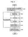
- FIG. 4 is a flowchart showing an operation to be performed when the predetermined photographing mode for allowing the digital camera 4 to function as a PC camera is set to the digital camera 4 in the state shown in FIG. 1 .
- the digital camera 4 of the document camera 3 photographs an arbitrary document material A or the like while the predetermined photographing mode is set thereto, and outputs image data of the photographed document to the PC 2 (step SA1).
- the PC 2 corrects the photographed image by applying various kinds of image processing such as distortion correction processing, rotation processing, clipping processing, etc. to the image data input thereto in accordance with the above-described image processing program, and outputs the processed image data to the projector 1 in accordance with the image display program (steps SA2 to SA5).
- the projector 1 projects an image based on the image data input from the PC 2 on the screen S (step SA6).
- the above-described image processing by the PC 2 is performed for a portion of the image or for the entire image according to necessity.
- FIG. 5 is a flowchart showing procedures of a process for registering front-photographing-corrected data performed when a play mode is set to the digital camera 4.
- a photographed image G (see FIG. 6 ) which is obtained when a user uses the digital camera 4 by detaching it from the stand 33 and photographs from an oblique position a whiteboard on which a document and other materials, etc. are projected with comments written thereon by handwriting using a marking pen, is stored in the memory card 53.
- the digital camera 4 reads data of a photographed image selected by the user from the memory card 53 in accordance with a predetermined key operation by the user, expands the read data in the DRAM 50, and displays it on the liquid crystal monitor 48 (step SB1).
- the digital camera 4 goes to the above-described registering process (step SB2: YES).
- the digital camera 4 performs line identification of the photographed image G now being displayed and recognizes continuity of identified lines to scan the contour of a quadrangularly closed shape (step SB3). If there is no contour (step SB4: NO), the digital camera 4 once terminates the registering process. In this case, the digital camera 4 may display a message like "there is no correction object" on the liquid crystal monitor 48.
- step SB4 the digital camera 4 displays a quadrangular frame F, which is a confirmation indicator of the present invention and which indicates the contour which is the correction candidate, upon the photographed image G being displayed, as shown in FIG. 6 (step SB5).
- the digital camera 4 displays a "correction” button B1 and a "cancel” button B2.
- the shown example illustrates a state where the photographed image G is constituted by regions of mainly a background Ga, a whiteboard Gb, and a projected image Gc, and a contour f1 enclosing the whiteboard Gb and a counter f2 enclosing the projected image Gc are scanned in step SB3, and the contour f1 of the whiteboard Gb is chosen as the correction candidate and the quadrangular frame F is thus displayed upon the contour f1.
- the quadrangular frame F is shown by a bold dashed line.
- the quadrangular frame F is actually displayed by a line having a red color, etc.
- step SB6 the digital camera 4 terminates the registering process likewise the case where there is no contour. If neither the button B1 nor the button B2 is selected but there is an operation for changing correction candidates by using the zoom key (step SB6: NO, step SB7: NO, step SB8: YES), the digital camera 4 changes the correction candidates (step SB9) and returns to step SB5 to display the quadrangular frame F upon the correction candidate selected by the change. That is, in the example of FIG.
- a quadrangular frame F that is overlaid upon the contour f2 enclosing the projected image Gc will be displayed. Further, though not illustrated, also in a case where there are a plurality of scanned contours and these contours are positioned side by side, the quadrangular frame F is moved to the respective contours in a predetermined order each time the zoom key is operated.
- step SB7 when there is an operation for selecting the "correction" button B1(a deciding operation) by the user (step SB7: YES), the digital camera 4 obtains coordinate information (data of pixel positions with respect to X and Y directions) 300 of four vertexes A, B, C, and D on the contour indicated by the quadrangular frame F at the time of selection of the correction button B1 (step SB10), records the obtained coordinate information in the header portion of the image data representing the photographed image G (step SB11), and ends the registering process.
- FIG. 7 is an exemplary diagram showing the structure of data of the photographed image G in which the coordinate information 300 is recorded.
- the coordinate information 300 is recorded in a user area "n" that is freely usable by the user and secured in a header area "m” in which meta-information other than image information (compressed image data) is stored in a JPEG file.
- FIG. 8 is a flowchart showing procedures of a process relating to front photographing correction performed by the PC 2 when the digital camera 4 is attached to the stand 33 and a predetermined projection control mode for controlling the projector 1 to project a photographed image stored in the digital camera 4 is set to the PC 2 by an operation of the user.
- This projection control mode is a mode for obtaining thumbnail images or the like of photographed images recorded in the memory card 53 from the digital camera 4 while an image transfer mode is set to the digital camera 4 and for displaying a list of photographed images on the display device 27 thereby allowing the user to select a photographed image to be projected.
- the PC 2 When a photographed image is selected by the user in the projection control mode, the PC 2 obtains the image file of the selected photographed image (step SC1), and checks whether the above-described coordinate information 300 is present in the header of the obtained file (step SC2). If no coordinate information 300 is stored (step SC3: NO), the PC 2 performs the ordinary image processing which is described with reference to FIG. 4 and which is performed when the predetermined photographing mode causing the digital camera 4 to function as a PC camera is set to the digital camera 4, and outputs the image data after being image-processed to the projector 1 (step SC4).
- the PC 2 obtains the coordinate information 300 (step SC5), and corrects the distortion in the image based on the coordinate information 300 (step SC6). That is, in a case where data of the four corners A to D of the contour f1 is stored in the header as the coordinate information 300, the PC 2 regards the region enclosed by the contour f1 as a correction reference and performs correction for making the region rectangular.
- the PC 2 clips the region enclosed by the contour f1 after being transformed (corrected) from the corrected image (step SC7), displays the clipped image on the display device 27, and at the same time, outputs the clipped image to the projector 1 (step SC8).
- the region within a photographed image that is to be distortion-corrected when it is actually projected can be preset while the digital camera 4 is used independently without being attached to the stand 33. That is, this setting operation can be performed immediately after photographing or at any convenient time and even in a case where there is no PC 2 at hand. Accordingly, if there is a need of preparing many images to be projected, this setting feature is helpful. Further, this setting feature is convenient because it makes it possible to pre-select the region to be used with its distortion corrected.
- the digital camera 4 makes it possible to check whether distortion correction of a desired region is possible or not immediately after an image is photographed. This is because in the process for registering front-photographing-corrected data which is explained with reference to FIG. 5 , a region that cannot be distortion-corrected does not become a correction candidate and this region cannot therefore be set as a correction candidate. Therefore, by performing this check immediately after photographing and by retrying photographing in some case, it is possible to obtain a necessary image without fail.
- the present invention is applicable to an imaging/projecting system which comprises, for example, only the projector 1 and the digital camera 4 connected to the projector 1.
- the above-described process performed by the PC 2 relating to front photographing correction may be performed by the projector 1, so that the projector 1 functions as the image processing apparatus of the present invention.
- the digital camera 4 which is used as the document camera 3 by being attached to the stand 33 and has a function for transferring a photographed image to the PC 2, has been explained as the electronic camera of the present invention.
- the present invention may be applied to a digital camera (including one that is built in a portable information terminal such as a cellular phone, a PDA (Personal Digital Assistant), etc.) which does not have a function for performing data communication with the PC 2, as long as it is configured to be able to supply its photographed image to the PC 2, etc. via, for example, the memory card 53.
- processing information to be added (registered) to a photographed image is the coordinate information 300 representing the region to be distortion-corrected.
- processing information to be added (registered) to a photographed image may be information that is not used for both of the above-described distortion correction and clipping of a preset region, but is used either one of distortion correction and clipping, or may be information that is to be used for other processing than these.
- processing information such as the coordinate information 300 or the like may not necessarily be data that is inseparably integral with data representing a photographed image, but may be data that is recorded in the memory card 53 or the like separately from the photographed image, as long as it is recorded in a state where its association with a corresponding photographed image is recognizable.
- the coordinate information 300 or the like be inseparably integral with image data (JPEG file) from which the coordinate information 300 is obtained because integral data can more easily be handled by the PC 2.
Landscapes
- Engineering & Computer Science (AREA)
- Multimedia (AREA)
- Signal Processing (AREA)
- Studio Devices (AREA)
- Image Processing (AREA)
- Closed-Circuit Television Systems (AREA)
- Facsimile Scanning Arrangements (AREA)
- Editing Of Facsimile Originals (AREA)
Claims (13)
- Elektronische Kamera, die umfasst:eine Bilderzeugungseinheit (41) zum Erzeugen eines Bildes eines Foto-Objektes;eine Speichereinheit (53) zum Speichern einer Vielzahl von Bilddateien, wobei jede Speichereinheit Bildinformationen umfasst, die ein mit der Bilderzeugungseinheit erzeugtes Bild repräsentieren; undeine Ermittlungseinheit (420) zum Ermitteln von Bearbeitungsinformationen, die zum Durchführen einer Verzerrungskorrektur an einem Bild verwendet werden, das durch eine der Vielzahl gespeicherter Bilddateien repräsentiert wird;dadurch gekennzeichnet, dassdie Ermittlungseinheit (420) so eingerichtet ist, dass sie die Bearbeitungsinformationen auf Basis des Bildes ermittelt, an dem die Verzerrungskorrektur durchgeführt werden soll, und die ermittelten Bearbeitungsinformationen speichert, indem sie die ermittelten Bearbeitungsinformationen zu der Bilddatei des Bildes hinzufügt, an dem die Verzerrungskorrektur durchgeführt werden soll.
- Elektronische Kamera nach Anspruch 1, wobei die durch die Ermittlungseinheit ermittelten Bearbeitungsinformationen Koordinateninformationen einschließen, die einen vorgegebenen Bereich innerhalb des Bildes angeben.
- Elektronische Kamera nach Anspruch 1 oder 2, die des Weiteren umfasst:eine Bildanzeigeeinheit (48) zum Anzeigen des Bildes, an dem die Verzerrungskorrektur und/oder Beschneidungs-Bearbeitung durchgeführt werden soll; undeine Steuereinheit (421), die die Bildanzeigeeinheit so steuert, dass sie einen Bestätigungshinweis, der einen Inhalt der durch die Ermittlungseinheit ermittelten Bearbeitungsinformationen angibt, zusammen mit dem Bild anzeigt, an dem die Verzerrungskorrektur-Bearbeitung und/oder Beschneidung durchgeführt werden soll.
- Elektronische Kamera nach Anspruch 3, wobei in einem Fall, in dem mehrere Elemente von Bearbeitungsinformationen vorhanden sind, die durch die Ermittlungseinheit ermittelt werden, die Steuereinheit die Bildanzeigeeinheit so steuert, dass sie Bestätigungshinweise anzeigt, die jeweils Inhalte der mehreren Elemente von Bearbeitungsinformationen angeben, indem sie die Hinweise in Reaktion auf einen Umschaltvorgang durch einen Benutzer umschaltet, und sie die Bearbeitungsinformationen, die einem Bestätigungshinweis entsprechen, der durch die Bildanzeigeeinheit angezeigt wird, in Reaktion auf einen Entscheidungsvorgang durch den Benutzer in der Speichereinheit (53) speichert.
- Elektronische Kamera nach einem der Ansprüche 1 bis 4, wobei die durch die Ermittlungseinheit ermittelten Bearbeitungsinformationen Koordinateninformationen einschließen, die einen vorgegebenen Bereich innerhalb des Bildes angeben.
- Bildbearbeitungssystem, das umfasst:eine elektronische Kamera (4) nach einem der Ansprüche 1 bis 5; undeine Bildbearbeitungsvorrichtung (2), die eine Bildbearbeitungseinheit (210) enthält, die die Verzerrungskorrektur an dem Bild, an dem die Verzerrungskorrektur durchgeführt werden soll, auf Basis der Bearbeitungsinformationen durchführt, die durch die elektronische Kamera in Verbindung mit dem Bild gespeichert werden.
- Bildbearbeitungsverfahren, das die folgenden Schritte umfasst:Erzeugen eines Bildes eines Photo-Objektes;Speichern einer Vielzahl von Bilddateien, wobei jede Bilddatei Bildinformationen umfasst, die ein mit dem Bilderzeugungsschritt erzeugtes Bild repräsentieren; undErmitteln von Bearbeitungsinformationen, die zum Durchführen einer Verzerrungskorrektur an einem Bild verwendet werden, das durch eine der Vielzahl gespeicherter Bilddateien repräsentiert wird;dadurch gekennzeichnet, dassdie Bearbeitungsinformationen auf Basis des Bildes ermittelt werden, an dem die Verzerrungskorrektur durchgeführt werden soll, und dadurch, dass es des Weiteren die folgenden Schritte umfasst:Speichern der ermittelten Bearbeitungsinformationen durch Hinzufügen der ermittelten Bearbeitungsinformationen zu der Bilddatei des Bildes, an dem die Verzerrungskorrektur durchgeführt werden soll.
- Bildbearbeitungsverfahren nach Anspruch 7, wobei die mit dem Ermittlungsschritt ermittelten Bearbeitungsinformationen Koordinateninformationen einschließen, die einen vorgegebenen Bereich innerhalb des Bildes angeben.
- Bildbearbeitungsverfahren nach Anspruch 7 oder 8, das des Weiteren die folgenden Schritte umfasst:Anzeigen des Bildes, an dem die Verzerrungskorrektur und/oder Beschneidungs-Bearbeitung durchgeführt werden soll; undSteuern des Bildanzeigeschritts so, dass ein Bestätigungshinweis, der einen Inhalt der mit dem Ermittlungsschritt ermittelten Bearbeitungsinformationen angibt, zusammen mit dem Bild angezeigt wird, an dem die Verzerrungskorrektur und/oder Beschneidungs-Bearbeitung durchgeführt werden soll.
- Bildbearbeitungsverfahren nach Anspruch 9, wobei in einem Fall, in dem mehrere Elemente von Bearbeitungsinformationen vorhanden sind, die mit dem Ermittlungsschritt ermittelt werden, mit dem Steuerschritt der Bildanzeigeschritt so gesteuert wird, dass Bestätigungshinweise angezeigt werden, die jeweils Inhalte der mehreren Elemente von Bearbeitungsinformationen angeben, indem die Hinweise in Reaktion auf einen Umschaltvorgang durch einen Benutzer umgeschaltet werden, und Bearbeitungsinformationen, die einem Bestätigungshinweis entsprechen, der mit dem Bildanzeigeschritt angezeigt wird, in dem Schritt zum Speichern von Bearbeitungsinformationen in Reaktion auf einen Entscheidungsvorgang durch den Benutzer gespeichert werden.
- Bildbearbeitungsverfahren nach einem Ansprüche 7 bis 10, wobei die mit dem Ermittlungsschritt ermittelten Bearbeitungsinformationen Koordinateninformationen einschließen, die einen vorgegebenen Bereich innerhalb des Bildes angeben.
- Bildbearbeitungsverfahren nach einem der Ansprüche 7 bis 11, das des Weiteren den Schritt umfasst, in dem die Verzerrungskorrektur an dem Bild, an dem die Verzerrungskorrektur durchgeführt werden soll, auf Basis der in Verbindung mit dem Bild gespeicherten Bearbeitungsinformationen durchgeführt wird.
- Computerprogrammerzeugnis, das ein computerlesbares Medium umfasst, auf dem computerlesbarer Programmcode enthalten ist, wobei der Programmcode zum Ausführen aller Schritte nach einem der Ansprüche 7 bis 12 eingerichtet ist.
Applications Claiming Priority (2)
| Application Number | Priority Date | Filing Date | Title |
|---|---|---|---|
| JP2003353622A JP3743828B2 (ja) | 2003-10-14 | 2003-10-14 | 電子カメラ |
| JP2003353622 | 2003-10-14 |
Publications (2)
| Publication Number | Publication Date |
|---|---|
| EP1524841A1 EP1524841A1 (de) | 2005-04-20 |
| EP1524841B1 true EP1524841B1 (de) | 2015-01-21 |
Family
ID=34373544
Family Applications (1)
| Application Number | Title | Priority Date | Filing Date |
|---|---|---|---|
| EP04024572.2A Expired - Lifetime EP1524841B1 (de) | 2003-10-14 | 2004-10-14 | Bildverarbeitungssystem und -verfahren sowie elektronische Kamera |
Country Status (5)
| Country | Link |
|---|---|
| US (1) | US7129974B2 (de) |
| EP (1) | EP1524841B1 (de) |
| JP (1) | JP3743828B2 (de) |
| KR (1) | KR100610582B1 (de) |
| CN (1) | CN1330179C (de) |
Families Citing this family (32)
| Publication number | Priority date | Publication date | Assignee | Title |
|---|---|---|---|---|
| JP4095491B2 (ja) * | 2003-05-19 | 2008-06-04 | 本田技研工業株式会社 | 距離測定装置、距離測定方法、及び距離測定プログラム |
| US20050068442A1 (en) * | 2003-09-26 | 2005-03-31 | Corey Billington | Presentation system and method of use |
| WO2007023715A1 (en) * | 2005-08-25 | 2007-03-01 | Ricoh Company, Ltd. | Image processing method and apparatus, digital camera, and recording medium recording image processing program |
| JP4344888B2 (ja) * | 2005-12-09 | 2009-10-14 | 株式会社カシオ日立モバイルコミュニケーションズ | 撮像装置、撮像画像処理方法及びプログラム |
| CN101366269B (zh) * | 2006-01-20 | 2010-11-03 | 索尼爱立信移动通讯股份有限公司 | 用于电子器件的照相机 |
| US7918614B2 (en) * | 2006-01-20 | 2011-04-05 | Sony Ericsson Mobile Communications Ab | Camera for electronic device |
| JP5074777B2 (ja) * | 2006-05-22 | 2012-11-14 | キヤノン株式会社 | 撮像機能付表示装置、画像処理装置、画像処理方法、および、画像表示システム |
| JP4854539B2 (ja) * | 2007-02-21 | 2012-01-18 | キヤノン株式会社 | 画像処理装置、その制御方法、及びプログラム |
| CN101287066A (zh) * | 2007-04-12 | 2008-10-15 | Hoya株式会社 | 摄像装置 |
| US7632102B2 (en) * | 2007-07-23 | 2009-12-15 | Antonio Macli | Classroom instructional tool |
| US20090059094A1 (en) * | 2007-09-04 | 2009-03-05 | Samsung Techwin Co., Ltd. | Apparatus and method for overlaying image in video presentation system having embedded operating system |
| US7391442B1 (en) | 2007-11-01 | 2008-06-24 | International Business Machines Corporation | Digital camera including a distortion correction system |
| JP5353154B2 (ja) * | 2008-09-25 | 2013-11-27 | オムロン株式会社 | 画像処理装置およびそれにおける画像処理方法 |
| JP5608980B2 (ja) * | 2009-01-27 | 2014-10-22 | セイコーエプソン株式会社 | 書画カメラおよび画像表示システム |
| JP4856263B2 (ja) * | 2009-08-07 | 2012-01-18 | シャープ株式会社 | 撮像画像処理システム、画像出力方法、プログラムおよび記録媒体 |
| JP4630936B1 (ja) * | 2009-10-28 | 2011-02-09 | シャープ株式会社 | 画像処理装置、画像処理方法、画像処理プログラム、画像処理プログラムを記録した記録媒体 |
| EP2529333A4 (de) | 2010-01-28 | 2013-10-23 | Pathway Innovations And Technologies Inc | Dokumentenabbildungssystem mit einer kamera-scanner-vorrichtung und einer pc-gestützten verarbeitungssoftware |
| BRPI1008318A2 (pt) * | 2010-03-31 | 2018-03-06 | Fujifilm Corp | "aparelho de formação de imagem estereoscópica" |
| BRPI1006035A2 (pt) * | 2010-03-31 | 2016-12-06 | Fujifilm Corp | "aparelho de coletar imagem estereiscópica ". |
| JP5135380B2 (ja) * | 2010-04-12 | 2013-02-06 | 住友重機械工業株式会社 | 処理対象画像生成装置、処理対象画像生成方法、及び操作支援システム |
| US8400564B2 (en) * | 2010-05-03 | 2013-03-19 | Microsoft Corporation | Image capture |
| US8781152B2 (en) * | 2010-08-05 | 2014-07-15 | Brian Momeyer | Identifying visual media content captured by camera-enabled mobile device |
| CN102073997B (zh) * | 2011-01-12 | 2012-11-07 | 东华理工大学 | 小型文档图像透视复原方法 |
| JP5724544B2 (ja) | 2011-03-31 | 2015-05-27 | ソニー株式会社 | 画像処理装置、画像処理方法及びプログラム |
| JP5802524B2 (ja) | 2011-11-21 | 2015-10-28 | 株式会社Pfu | 画像処理装置、画像処理方法、および画像処理プログラム |
| KR102173109B1 (ko) | 2014-09-05 | 2020-11-02 | 삼성전자주식회사 | 디지털 영상 처리 방법, 상기 방법을 기록한 컴퓨터 판독 가능 저장매체 및 디지털 영상 처리 장치 |
| KR102279026B1 (ko) * | 2014-11-07 | 2021-07-19 | 삼성전자주식회사 | 적어도 하나의 객체를 포함하는 영상에서 객체를 추출하여 보정한 영상을 제공하는 장치 및 방법 |
| KR102272310B1 (ko) | 2014-11-18 | 2021-07-02 | 삼성전자주식회사 | 영상 처리 방법, 상기 방법을 기록한 컴퓨터 판독 가능 저장매체 및 전자 기기. |
| CN104754224A (zh) * | 2015-03-23 | 2015-07-01 | 联想(北京)有限公司 | 一种信息处理方法及电子设备 |
| CN105173038A (zh) * | 2015-08-05 | 2015-12-23 | 魏芳 | 结合小波滤波和中值滤波的船下暗礁识别装置 |
| JP6797046B2 (ja) * | 2017-02-22 | 2020-12-09 | 株式会社日立情報通信エンジニアリング | 画像処理装置及び画像処理プログラム |
| US10970576B2 (en) * | 2018-08-27 | 2021-04-06 | Daon Holdings Limited | Methods and systems for capturing image data |
Citations (4)
| Publication number | Priority date | Publication date | Assignee | Title |
|---|---|---|---|---|
| US5428721A (en) * | 1990-02-07 | 1995-06-27 | Kabushiki Kaisha Toshiba | Data processing apparatus for editing image by using image conversion |
| JP2000138856A (ja) * | 1998-10-29 | 2000-05-16 | Seiko Epson Corp | 画像入力装置、プレゼンテーションシステム及び情報記憶媒体 |
| US20020018138A1 (en) * | 2000-05-16 | 2002-02-14 | Yamazaki Yoshiro | Image pickup device, image pickup device control method and image processing method |
| EP1276074A2 (de) * | 2001-07-09 | 2003-01-15 | Xerox Corporation | Verfahren und Vorrichtung zur Korrektur von perspektivischen Verzerrungen in Dokumentbildern und zur Summierung von Bildzeilen |
Family Cites Families (16)
| Publication number | Priority date | Publication date | Assignee | Title |
|---|---|---|---|---|
| JP2929802B2 (ja) * | 1991-09-20 | 1999-08-03 | 株式会社デンソー | 指紋照合システム |
| JPH08256295A (ja) * | 1994-12-21 | 1996-10-01 | Olympus Optical Co Ltd | 画像処理装置 |
| US6493025B1 (en) | 1995-10-05 | 2002-12-10 | Sanyo Electronic Co., Ltd. | Image sensing system equipped with interface between image sensing apparatus and computer machinery |
| US5760925A (en) * | 1996-05-30 | 1998-06-02 | Xerox Corporation | Platenless book scanning system with a general imaging geometry |
| US6219129B1 (en) * | 1997-09-11 | 2001-04-17 | Fuji Photo Film Co., Ltd. | Print system |
| DE69820871T2 (de) | 1998-07-08 | 2004-12-16 | Hewlett-Packard Co. (N.D.Ges.D.Staates Delaware), Palo Alto | Kamera mit Vorrichtung zur Korrektur des Trapezoidalbildfehlers |
| JP3762140B2 (ja) | 1999-05-20 | 2006-04-05 | キヤノン株式会社 | 情報処理装置及びその制御方法、撮像装置及びその制御方法、並びにコンピュータ読み取り可能な記録媒体 |
| EP1067362A1 (de) | 1999-07-09 | 2001-01-10 | Hewlett-Packard Company | Bilderzeugungssystem für Dokumente |
| JP4688246B2 (ja) | 1999-08-17 | 2011-05-25 | 株式会社ニコン | 画像処理パラメータの受け渡し方法、画像入力装置、画像入力システム、および情報処理装置の画像処理パラメータ受け渡しプログラムを記憶した記憶媒体 |
| JP4700164B2 (ja) * | 2000-04-24 | 2011-06-15 | 富士フイルム株式会社 | 画像記録装置及び方法 |
| JP2002074351A (ja) | 2000-08-30 | 2002-03-15 | Minolta Co Ltd | 歪み補正装置およびその方法ならびに歪み補正プログラムを記録したコンピュータ読み取り可能な記録媒体 |
| JP2002325200A (ja) * | 2001-04-26 | 2002-11-08 | Victor Co Of Japan Ltd | 資料提示装置 |
| JP2002354331A (ja) | 2001-05-25 | 2002-12-06 | Canon Inc | 画像撮影装置および電子機器 |
| JP2003283964A (ja) * | 2002-03-26 | 2003-10-03 | Olympus Optical Co Ltd | 映像表示装置 |
| JP3879560B2 (ja) * | 2002-03-27 | 2007-02-14 | セイコーエプソン株式会社 | 投写型画像表示装置 |
| NZ518092A (en) | 2002-03-28 | 2004-11-26 | Pulse Data Internat Ltd | Low vision video magnifier viewing apparatus having digital zoom feature |
-
2003
- 2003-10-14 JP JP2003353622A patent/JP3743828B2/ja not_active Expired - Fee Related
-
2004
- 2004-10-12 CN CNB2004100951094A patent/CN1330179C/zh not_active Expired - Fee Related
- 2004-10-13 KR KR1020040081599A patent/KR100610582B1/ko not_active Expired - Fee Related
- 2004-10-13 US US10/965,102 patent/US7129974B2/en not_active Expired - Lifetime
- 2004-10-14 EP EP04024572.2A patent/EP1524841B1/de not_active Expired - Lifetime
Patent Citations (4)
| Publication number | Priority date | Publication date | Assignee | Title |
|---|---|---|---|---|
| US5428721A (en) * | 1990-02-07 | 1995-06-27 | Kabushiki Kaisha Toshiba | Data processing apparatus for editing image by using image conversion |
| JP2000138856A (ja) * | 1998-10-29 | 2000-05-16 | Seiko Epson Corp | 画像入力装置、プレゼンテーションシステム及び情報記憶媒体 |
| US20020018138A1 (en) * | 2000-05-16 | 2002-02-14 | Yamazaki Yoshiro | Image pickup device, image pickup device control method and image processing method |
| EP1276074A2 (de) * | 2001-07-09 | 2003-01-15 | Xerox Corporation | Verfahren und Vorrichtung zur Korrektur von perspektivischen Verzerrungen in Dokumentbildern und zur Summierung von Bildzeilen |
Also Published As
| Publication number | Publication date |
|---|---|
| US7129974B2 (en) | 2006-10-31 |
| CN1607824A (zh) | 2005-04-20 |
| KR20050036744A (ko) | 2005-04-20 |
| JP2005123708A (ja) | 2005-05-12 |
| CN1330179C (zh) | 2007-08-01 |
| EP1524841A1 (de) | 2005-04-20 |
| US20050078200A1 (en) | 2005-04-14 |
| JP3743828B2 (ja) | 2006-02-08 |
| KR100610582B1 (ko) | 2006-08-09 |
Similar Documents
| Publication | Publication Date | Title |
|---|---|---|
| US7129974B2 (en) | Image processing system, image processing method, electronic camera, and image processing apparatus camera system which obtain information for performing distortion correction processing | |
| TWI268096B (en) | Image processing apparatus for correcting distortion of image, image shooting apparatus for correcting distortion of shot image and recordable medium | |
| US7760962B2 (en) | Image capture apparatus which synthesizes a plurality of images obtained by shooting a subject from different directions, to produce an image in which the influence of glare from a light is reduced | |
| KR100656780B1 (ko) | 해상도의 변환기능을 구비한 표시화상생성장치, 촬상투영장치, 촬상투영시스템, 이에 관련된 생성방법 및 관련프로그램이 기록된 기록매체 | |
| JP2008283361A (ja) | 画像処理装置、画像処理方法、プログラムおよび記録媒体 | |
| JP2004135354A (ja) | 表示装置を有するデジタル画像形成システムを用いて少なくとも1つのデジタル画像を見る方法 | |
| JP4556813B2 (ja) | 画像処理装置、及びプログラム | |
| JP7179446B2 (ja) | 情報処理装置、情報処理方法、および、プログラム | |
| JP2004343476A (ja) | 撮像装置、撮像結果の処理装置及び撮像結果の処理方法 | |
| JP2007074578A (ja) | 画像処理装置、撮影装置、及びプログラム | |
| JP4648042B2 (ja) | 画像処理システム | |
| KR100627020B1 (ko) | 영상합성장치, 전자카메라 및 영상합성방법 | |
| JP2001008072A (ja) | 電子カメラ及びその制御方法 | |
| US7679792B2 (en) | Merged camera and scanner | |
| JP4561399B2 (ja) | 画像記録方法、及びカメラ装置 | |
| JP4561397B2 (ja) | 画像取得方法、及びカメラ装置 | |
| JP2006053313A (ja) | 撮影機能付き映像投射装置およびそれを用いたデータ管理システム | |
| JP4905017B2 (ja) | 画像表示装置及びプログラム | |
| JP5200816B2 (ja) | 撮像装置、撮像装置の画像処理方法及び画像処理プログラム | |
| JP2002305676A (ja) | 電子カメラ | |
| JP4127279B2 (ja) | 画像処理システム及び画像処理方法と、電子カメラ | |
| JP4600123B2 (ja) | 撮像投影システム及び撮影画像の保存方法及びプログラム | |
| JP5606057B2 (ja) | 撮像装置、画像処理装置、画像処理方法 | |
| JP4396562B2 (ja) | 撮像装置、及び画質表示方法 | |
| JP3786270B2 (ja) | ディジタルカメラ |
Legal Events
| Date | Code | Title | Description |
|---|---|---|---|
| PUAI | Public reference made under article 153(3) epc to a published international application that has entered the european phase |
Free format text: ORIGINAL CODE: 0009012 |
|
| 17P | Request for examination filed |
Effective date: 20041014 |
|
| AK | Designated contracting states |
Kind code of ref document: A1 Designated state(s): AT BE BG CH CY CZ DE DK EE ES FI FR GB GR HU IE IT LI LU MC NL PL PT RO SE SI SK TR |
|
| AX | Request for extension of the european patent |
Extension state: AL HR LT LV MK |
|
| AKX | Designation fees paid |
Designated state(s): DE FR GB |
|
| 17Q | First examination report despatched |
Effective date: 20071123 |
|
| GRAP | Despatch of communication of intention to grant a patent |
Free format text: ORIGINAL CODE: EPIDOSNIGR1 |
|
| INTG | Intention to grant announced |
Effective date: 20140911 |
|
| GRAS | Grant fee paid |
Free format text: ORIGINAL CODE: EPIDOSNIGR3 |
|
| GRAA | (expected) grant |
Free format text: ORIGINAL CODE: 0009210 |
|
| AK | Designated contracting states |
Kind code of ref document: B1 Designated state(s): DE FR GB |
|
| REG | Reference to a national code |
Ref country code: GB Ref legal event code: FG4D |
|
| REG | Reference to a national code |
Ref country code: DE Ref legal event code: R096 Ref document number: 602004046538 Country of ref document: DE Effective date: 20150226 |
|
| REG | Reference to a national code |
Ref country code: DE Ref legal event code: R097 Ref document number: 602004046538 Country of ref document: DE |
|
| REG | Reference to a national code |
Ref country code: FR Ref legal event code: PLFP Year of fee payment: 12 |
|
| PLBE | No opposition filed within time limit |
Free format text: ORIGINAL CODE: 0009261 |
|
| STAA | Information on the status of an ep patent application or granted ep patent |
Free format text: STATUS: NO OPPOSITION FILED WITHIN TIME LIMIT |
|
| 26N | No opposition filed |
Effective date: 20151022 |
|
| REG | Reference to a national code |
Ref country code: FR Ref legal event code: PLFP Year of fee payment: 13 |
|
| REG | Reference to a national code |
Ref country code: FR Ref legal event code: PLFP Year of fee payment: 14 |
|
| REG | Reference to a national code |
Ref country code: FR Ref legal event code: PLFP Year of fee payment: 15 |
|
| PGFP | Annual fee paid to national office [announced via postgrant information from national office to epo] |
Ref country code: FR Payment date: 20180913 Year of fee payment: 15 |
|
| PGFP | Annual fee paid to national office [announced via postgrant information from national office to epo] |
Ref country code: DE Payment date: 20181002 Year of fee payment: 15 |
|
| PGFP | Annual fee paid to national office [announced via postgrant information from national office to epo] |
Ref country code: GB Payment date: 20181010 Year of fee payment: 15 |
|
| REG | Reference to a national code |
Ref country code: DE Ref legal event code: R119 Ref document number: 602004046538 Country of ref document: DE |
|
| PG25 | Lapsed in a contracting state [announced via postgrant information from national office to epo] |
Ref country code: DE Free format text: LAPSE BECAUSE OF NON-PAYMENT OF DUE FEES Effective date: 20200501 |
|
| GBPC | Gb: european patent ceased through non-payment of renewal fee |
Effective date: 20191014 |
|
| PG25 | Lapsed in a contracting state [announced via postgrant information from national office to epo] |
Ref country code: GB Free format text: LAPSE BECAUSE OF NON-PAYMENT OF DUE FEES Effective date: 20191014 Ref country code: FR Free format text: LAPSE BECAUSE OF NON-PAYMENT OF DUE FEES Effective date: 20191031 |