EP1525352B1 - Dispositif a bande tissee - Google Patents
Dispositif a bande tissee Download PDFInfo
- Publication number
- EP1525352B1 EP1525352B1 EP03726997A EP03726997A EP1525352B1 EP 1525352 B1 EP1525352 B1 EP 1525352B1 EP 03726997 A EP03726997 A EP 03726997A EP 03726997 A EP03726997 A EP 03726997A EP 1525352 B1 EP1525352 B1 EP 1525352B1
- Authority
- EP
- European Patent Office
- Prior art keywords
- woven fabric
- fabric belt
- longitudinal
- yarns
- anyone
- Prior art date
- Legal status (The legal status is an assumption and is not a legal conclusion. Google has not performed a legal analysis and makes no representation as to the accuracy of the status listed.)
- Expired - Lifetime
Links
- 239000002759 woven fabric Substances 0.000 title claims 35
- 239000004744 fabric Substances 0.000 claims description 84
- 238000010438 heat treatment Methods 0.000 claims description 3
- 238000004826 seaming Methods 0.000 claims 5
- 238000009941 weaving Methods 0.000 description 5
- 230000008878 coupling Effects 0.000 description 2
- 238000010168 coupling process Methods 0.000 description 2
- 238000005859 coupling reaction Methods 0.000 description 2
- 230000001681 protective effect Effects 0.000 description 2
- 230000008719 thickening Effects 0.000 description 2
- 230000007704 transition Effects 0.000 description 2
- WYTGDNHDOZPMIW-RCBQFDQVSA-N alstonine Natural products C1=CC2=C3C=CC=CC3=NC2=C2N1C[C@H]1[C@H](C)OC=C(C(=O)OC)[C@H]1C2 WYTGDNHDOZPMIW-RCBQFDQVSA-N 0.000 description 1
- 230000009286 beneficial effect Effects 0.000 description 1
- 230000015572 biosynthetic process Effects 0.000 description 1
- 150000001875 compounds Chemical class 0.000 description 1
- 238000011109 contamination Methods 0.000 description 1
- 230000002349 favourable effect Effects 0.000 description 1
- 238000009998 heat setting Methods 0.000 description 1
- 238000004519 manufacturing process Methods 0.000 description 1
- 238000000034 method Methods 0.000 description 1
- 238000012216 screening Methods 0.000 description 1
- 239000000126 substance Substances 0.000 description 1
Images

Classifications
-
- D—TEXTILES; PAPER
- D21—PAPER-MAKING; PRODUCTION OF CELLULOSE
- D21F—PAPER-MAKING MACHINES; METHODS OF PRODUCING PAPER THEREON
- D21F1/00—Wet end of machines for making continuous webs of paper
- D21F1/0027—Screen-cloths
- D21F1/0054—Seams thereof
-
- Y—GENERAL TAGGING OF NEW TECHNOLOGICAL DEVELOPMENTS; GENERAL TAGGING OF CROSS-SECTIONAL TECHNOLOGIES SPANNING OVER SEVERAL SECTIONS OF THE IPC; TECHNICAL SUBJECTS COVERED BY FORMER USPC CROSS-REFERENCE ART COLLECTIONS [XRACs] AND DIGESTS
- Y10—TECHNICAL SUBJECTS COVERED BY FORMER USPC
- Y10S—TECHNICAL SUBJECTS COVERED BY FORMER USPC CROSS-REFERENCE ART COLLECTIONS [XRACs] AND DIGESTS
- Y10S162/00—Paper making and fiber liberation
- Y10S162/90—Papermaking press felts
Definitions
- the invention relates to a fabric tape device, e.g. Endless screening belt for paper and pulp machines, in which at least one end of the fabric belt, a connection device is provided which is connected via a releasable connection means with another connection device of the same or another, wherein a number of specific longitudinal threads along one of the end of the fabric band associated Section is removed from the tissue, wherein the removed portions of the longitudinal threads are disposed on at least one side of the fabric band in a region in front of the connecting device, so that they form a support for protecting the connection devices in running over a work surface fabric tape.
- a fabric tape device e.g. Endless screening belt for paper and pulp machines
- Detachable connections between the two front ends of a fabric belt or between the ends of two different fabric belts such as conveyor belts, Endlossiebb software od.
- the connection devices for these detachable connections are designed either as individual coupling eyes, as helical coils or as seam loops.
- the coupling eyelets or helical coils may be sewn to the end of the fabric or woven into the fabric, whereas seam loops may be made either by the fabric structure itself or by weaving individual longitudinal threads back into the fabric in accordance with the bond.
- a connecting means is a pintle, which is inserted after joining the connection devices through the eyelets, helices or suture loops of these connection devices.
- the pintle may be straight or spiral and have a round or oval cross-section.
- connection devices are subject to wear which can affect the life of the belt, especially when the fabric connection is subjected to heavy mechanical loads or increased contamination.
- a detachable connection of the type mentioned above is in the FR 2 145 365 A has been proposed to provide the connection devices with a flat cover which is attached to a fabric end.
- a cover protects the connection, but has the disadvantage that, on the one hand thereby additional manufacturing costs incurred, on the other hand, the fabric tape is thicker at the junction and therefore for certain purposes under Circumstances is not suitable or at least there is subject to increased wear, which in turn reduces the life of the fabric tape.
- a disadvantage of this device is that when using the fabric tape device under certain conditions, the situation occurs that one or more of the longitudinal threads are lifted and bent from the fabric tape. It may then happen that thread the threads in the connection device and this is damaged.
- a seam protection for paper machine screens is from the DE 536 605 known.
- the sieve on its underside a ramp-shaped elevation, which is formed for example by cranked warp threads.
- a disadvantage of this embodiment of a paper machine screen is that this seam protection can be damaged relatively easily, for example by the threads being lifted or pulled out of the fabric.
- connection device In this way, a kind of "thickening" is achieved in the region in front of at least one connection device, which prevents the connection device from coming into contact with the work surface in the case of a fabric belt running over a work surface and thus can not be damaged.
- the removed threads form this support - the threads usually limit a fictitious "support surface", so that in the following description of "support surface” synonymous for support is mentioned - in a “range” before at least one connection device, where they Of course, in both areas can form a thickening.
- support surface synonymous for support
- the support surface can be designed to be particularly stable in that, according to the invention, the removed sections of the longitudinal threads are woven around transverse threads and are backwoven with them.
- the region of the support surface extends directly to the connection device, but it can also terminate at a distance in front of the connection device.
- the extent of the area depends on the expected load in use, the purpose, the work surface, etc., and also on the thickness of the support surface. In general, however, it will be beneficial to guide the support surface as close as possible to the connection device, so that optimum protection is ensured, but without affecting the running properties of the fabric tape on the work surface.
- the stability of the fabric tape device and thus also its service life can be increased by the fact that in a fabric tape region following the region with transverse threads and extending in a direction away from the connection device, the longitudinal threads are woven back into the fabric tape.
- transverse threads are arranged on a side of the fabric strip facing the working surface in the region in front of the supporting surface. In this way, in particular if the transverse threads are arranged in two or more layers, it is also possible to increase the thickness of the support surface.
- the support surface is connected to the fabric tape when at least the cross-thread closest to the connecting device is interwoven with the fabric tape.
- the longitudinal threads have different dimensions with regard to their length taken out. This is achieved, for example, by the longitudinal threads being removed from the fabric band at different points relative to the longitudinal direction of the fabric band. With this Arrangement is achieved that the "transition" from the fabric tape to the support surface is not abrupt but running across the width of the fabric tape device, so that the device can run much more uniformly over the work surface.
- the number of removed longitudinal threads is assigned only to the lateral edge region of the fabric band.
- it can additionally be achieved that an effective protection of the generally particularly susceptible to wear edge region of a compound is achieved.
- a particularly good protection can be achieved if the number of removed longitudinal threads is distributed uniformly over the entire width of the fabric tape.
- connection device is a seam loop row extending at the end of the fabric band or a seam spiral of a seam attached to this end and when the connection means is a seam connection plug wire of a seam joining two seam loops or a seam spiral.
- the seam loop rows or the fastening of the suture spiral at the end of the fabric band are formed by certain longitudinally removed filaments and weaving back into the fabric in sections weave adjacent longitudinal filaments, according to the invention longitudinal threads are removed only at those points from the tissue to which the adjacent longitudinal threads are woven back into the tissue and the portions of the removed longitudinal threads form the protective pad.
- a special connection technique is utilized to make the support surface.
- suture loops are usually made by removing certain longitudinal sutures along a section from the tissue to weave adjacent longitudinal sutures back into the tissue to form a suture loop in that the removed longitudinal threads are usually cut off at the point where they leave the tissue.
- the removed threads form the support surface in front of the connecting device, and must not be cut off at the point where they are taken out of the fabric.
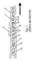
- FIG. 1 It can be seen that the fabric of a known endless screen of longitudinal threads 2 and transverse threads 6 is made. Seam loops are provided at the end of the fabric for attachment of a suture spiral 7a, which are produced by weaving back a section 1a of the longitudinal thread 1 into the fabric in accordance with the binding. In order to facilitate or facilitate this backward weaving, an adjacent longitudinal thread 2 has been removed from the fabric along a section 4. At the other end of the fabric band, another suture spiral 7b is attached in a similar or similar manner. The spirals 7a and 7b which are of oval design in the present embodiment can be pushed into one another laterally and are replaced by a single or multiple elements which can be inserted parallel to the end of the fabric (see FIG FIG. 2 ) Plug wires 9 held together.
- the end of the backwoven portion 1a of the longitudinal thread 1 protrudes in the embodiment shown by a transverse thread 6 further into the tissue than the section 4 of the longitudinal thread 2 is removed from the fabric so that at their overlap region 3, a so-called overlay is formed, which is a better Halt the back-woven portion 1 a in the fabric structure causes.
- a holding wire 8 running essentially parallel to the single or multiple plug wire 9 is additionally provided in each case in the exemplary embodiment shown.
- the section 4 of the longitudinal thread is not cut off at the point where it leaves the fabric in the shown prior art, but is placed over the suture spirals 7a, 7b, to serve as a seam protection, the end of the section 4 against the Direction indicated by an arrow direction of the endless screen is directed so that no further attachment of the sections 4 is required.
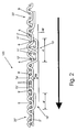
- FIG. 2 and 3 can be seen, thereby form the removed portions 4 ', 4 "of the threads 2', Y 'only in a region in front of the connecting device 7a', 7b 'a support 10', 10".
- the fabric tape device 100 runs over a work surface AF, for example, vacuum zone cover on a chemical washer, Seihzonentischabdeckung, etc.
- a work surface AF for example, vacuum zone cover on a chemical washer, Seihzonentischabdeckung, etc.
- the formation of supports 10 ', 10 "results in an exemption FR of the connection devices 7a', 7b 'of the work surface AF, the connection devices 7a ', 7b' are therefore not on the work surface AF and can therefore not be damaged by this.
- the removed longitudinal threads 2 " which form a bearing surface 10" can only be cut off in front of the corresponding connecting device 7b 'adjoining the fabric band 20 ", so that a support 10" can easily be produced.
- the direction of the fabric tape must be chosen so that the open ends of the support are facing away from the direction of movement, so that the threads are not bent and so the support is damaged.
- the correspondingly correctly selected direction of movement is in the Figures 2 and 3 indicated by an arrow.
- a support 10 ' Much more stable and additionally independent of the direction of the fabric tape device is a support 10 ', if as FIG. 2 and 3 further, removed sections 4 'of longitudinal threads 2' are woven around transverse threads 11 'and are backwoven with them. This results in a stable and relatively thick support surface 10 '.
- the longitudinal threads 2' are backwoven with the fabric tape.
- the transverse threads 11 ' are in this case also advantageously arranged on the underside of the fabric band in the area in front of the connection device 7a' in the area provided in front of the connection device 7a ', so that a comparatively high support surface 10' results.
- transverse thread 12 ' closest to the connecting device 7a', but as a rule a plurality of transverse threads 11 ', are interwoven with the fabric tape.
- the longitudinal threads 2 ' have different dimensions with regard to their removed length 4', for example by the longitudinal threads being removed from the fabric band at different locations relative to the longitudinal direction of the fabric band, so that an overly abrupt transition from the fabric band is avoided Fabric tape to the support surface 10 'results.
- the support surfaces 10 'serving as seam protection and formed by the removed longitudinal threads can also be arranged above the fabric or on both sides of the fabric. It is also possible that the removed longitudinal threads are not distributed uniformly over the width of the fabric tape, but are assigned only to the lateral edge of the fabric tape to form a wear protection for this lateral edge region.
- the Verschndschutz can also be provided only at the high stress points of the fabric connection.
- the sections 4 "of the longitudinal threads 2" removed from the fabric are cut off in front of the connection device 7b', so that on the one hand they also form a support surface 10 "for protecting the connection device, but on the other hand Due to the length of the removed sections of the threads, it is also not possible for them to get caught in the connecting device. Due to the direction of movement (see arrow), weaving back of the threads 4 "is not absolutely necessary.
- a corresponding support surface is formed on the end of the endless sieve associated with the suture spiral 7b 'as at the end of the suture spiral 7a', resulting in an even better support and a even better protection of the connection devices 7a ', 7b' results, but it can also be provided - as is also covered by the presently claimed protection claims - that a support is provided only in an area in front of a connection device 7a ', 7b' that Thus, only one of the supports 10 ', 10 "is present, if this is designed so as to provide sufficient protection for the connection devices 7a', 7b '.
- the length of the region of the support surface 10 ' may be sized differently depending on the application, typical values are approximately 20 cm. A particularly good protection results if the supporting surface 10 'is brought up to the connecting device 7a', but in principle it can also end at a distance in front of the connecting device 7a '.
Landscapes
- Woven Fabrics (AREA)
- Paper (AREA)
Claims (16)
- Dispositif à bande tissée, par exemple bande de tamis sans fin pour machines à papier et cellulose, dans lequel sur au moins une extrémité de la bande tissée (20', 20") est prévu un dispositif de raccordement (7a' ; 7b') qui peut être relié par un moyen de liaison (9) détachable à un autre dispositif de raccordement (7b' ; 7a') de celle-ci ou d'une autre bande tissée, dans lequel un nombre de fils longitudinaux (2', 2") déterminé peut être retiré du tissu (20') le long d'une section (4', 4") associée à l'extrémité de la bande tissée, dans lequel les sections (4', 4") retirées des fils longitudinaux (2', 2") sont disposées reposant sur au moins un côté de la bande tissée (20', 20") dans une zone avant le dispositif de raccordement (7a' ; 7b') de sorte que celles-ci forment un appui (10' ; 10") pour la protection des dispositifs de raccordement (7a' ; 7b') lorsque la bande tissée circule sur une surface de travail (AF), caractérisé en ce que les sections (4') retirées des fils longitudinaux (2') sont tissées autour de fils transversaux (11', 12') et retissées avec ceux-ci.
- Dispositif à bande tissée selon la revendication 1, caractérisé en ce que les sections (4', 4") retirées des fils longitudinaux (2' ; 2") ne recouvrent pas le dispositif de raccordement (7a', 7b').
- Dispositif à bande tissée selon la revendication 1 ou 2, caractérisé en ce que la zone de l'appui (10', 10") atteint directement le dispositif de raccordement (7a' ; 7b').
- Dispositif à bande tissée selon la revendication 1 ou 2, caractérisé en ce que la zone de la surface d'appui (10', 10") se termine à une distance avant le dispositif de raccordement (7a' ; 7b').
- Dispositif à bande tissée selon l'une quelconque des revendications 1 à 4, caractérisé en ce que les fils longitudinaux (2') sont retissés avec la bande tissée dans une zone de bande tissée jouxtant la zone avec des fils transversaux (11', 12') et s'étendant dans une direction à partir du dispositif de raccordement (7a').
- Dispositif à bande tissée selon l'une quelconque des revendications 1 à 5, caractérisé en ce que les fils transversaux (11', 12') sont disposés sur un côté de la bande tissée tourné vers la surface de travail (AF), vu dans le sens de déplacement, dans une zone avant la zone d'appui (7a').
- Dispositif à bande tissée selon l'une quelconque des revendications 1 à 6, caractérisé en ce que les fils transversaux (11', 12') sont disposés en deux ou plusieurs couches.
- Dispositif à bande tissée selon l'une quelconque des revendications 1 à 7, caractérisé en ce qu'au moins le fil transversal (12') le plus proche du dispositif de raccordement (7a') est tissé avec la bande tissée (20').
- Dispositif à bande tissée selon l'une quelconque des revendications 1 à 8, caractérisé en ce que les fils longitudinaux (2', 2") présentent différentes dimensions en ce qui concerne leur longueur (4', 4") retirée.
- Dispositif à bande tissée selon la revendication 9, caractérisé en ce que les fils longitudinaux (2', 2") sont retirés de la bande tissée (20', 20") à différents endroits par rapport au sens longitudinal de la bande tissée.
- Dispositif à bande tissée selon l'une quelconque des revendications 1 à 10, caractérisé en ce que le nombre de fils longitudinaux (2', 2") retirés n'est associé qu'à la zone de bord latérale de la bande tissée (20', 20").
- Dispositif à bande tissée selon l'une quelconque des revendications 1 à 10, caractérisé en ce que le nombre de fils longitudinaux (2', 2") retirés est réparti régulièrement sur toute la largeur de la bande tissée (20', 20").
- Dispositif à bande tissée selon l'une quelconque des revendications 1 à 12, dans lequel le tissu (20, 20") est fabriqué en fils synthétiques, caractérisé en ce que les sections (4, 4") retirées des fils longitudinaux (2', 2") du tissu sont égalisées thermiquement par échauffement sous tension longitudinale.
- Dispositif à bande tissée selon l'une quelconque des revendications 1 à 13, caractérisé en ce que le dispositif de raccordement est une rangée de boucles de soudure s'étendant au niveau de l'extrémité de la bande tissée ou une spirale de soudure (7a', 7b') fixée sur cette extrémité d'une soudure à emboîtement.
- Dispositif à bande tissée selon la revendication 14, caractérisé en ce que le moyen de liaison est un fil de connexion d'assemblage soudé (9') d'une soudure à emboîtement reliant deux boucles de soudure ou spirales de soudure (7a', 7b').
- Dispositif à bande tissée selon la revendication 14 ou 15, dans lequel la rangée de boucles de soudure ou la fixation de la spirale de soudure (7a', 7b') sur l'extrémité de la bande tissée est formée par des fils longitudinaux (2', 2") déterminés, retirés par endroits et par des fils longitudinaux contigus, retissés par endroits de manière conforme à la fixation dans le tissu (20', 20"), caractérisé en ce que des fils longitudinaux (2', 2") ne sont retirés du tissu qu'aux endroits, sur lesquels les fils longitudinaux contigus sont retissés dans le tissu.
Priority Applications (2)
| Application Number | Priority Date | Filing Date | Title |
|---|---|---|---|
| AT03726997T ATE431870T1 (de) | 2002-07-05 | 2003-05-28 | Gewebeband-einrichtung |
| SI200331645T SI1525352T1 (sl) | 2002-07-05 | 2003-05-28 | Naprava, katere osnova je tkan pas |
Applications Claiming Priority (3)
| Application Number | Priority Date | Filing Date | Title |
|---|---|---|---|
| AT0101002A AT411605B (de) | 2002-07-05 | 2002-07-05 | Gewebeband-einrichtung |
| AT10102002 | 2002-07-05 | ||
| PCT/AT2003/000159 WO2004005612A1 (fr) | 2002-07-05 | 2003-05-28 | Dispositif à bande tissée |
Publications (2)
| Publication Number | Publication Date |
|---|---|
| EP1525352A1 EP1525352A1 (fr) | 2005-04-27 |
| EP1525352B1 true EP1525352B1 (fr) | 2009-05-20 |
Family
ID=27625625
Family Applications (1)
| Application Number | Title | Priority Date | Filing Date |
|---|---|---|---|
| EP03726997A Expired - Lifetime EP1525352B1 (fr) | 2002-07-05 | 2003-05-28 | Dispositif a bande tissee |
Country Status (11)
| Country | Link |
|---|---|
| US (1) | US7036533B2 (fr) |
| EP (1) | EP1525352B1 (fr) |
| AT (2) | AT411605B (fr) |
| AU (1) | AU2003232915B2 (fr) |
| CA (1) | CA2491517C (fr) |
| DE (1) | DE50311534D1 (fr) |
| NZ (1) | NZ538018A (fr) |
| PT (1) | PT1525352E (fr) |
| RU (1) | RU2301857C2 (fr) |
| SI (1) | SI1525352T1 (fr) |
| WO (1) | WO2004005612A1 (fr) |
Families Citing this family (34)
| Publication number | Priority date | Publication date | Assignee | Title |
|---|---|---|---|---|
| EP1808527A1 (fr) * | 2006-01-17 | 2007-07-18 | Voith Patent GmbH | Feutre d'essorage à couture et son procédé de fabrication |
| US7360560B2 (en) * | 2006-01-31 | 2008-04-22 | Astenjohnson, Inc. | Single layer papermakers fabric |
| US10632740B2 (en) | 2010-04-23 | 2020-04-28 | Landa Corporation Ltd. | Digital printing process |
| WO2013132418A2 (fr) | 2012-03-05 | 2013-09-12 | Landa Corporation Limited | Procédé d'impression numérique |
| US9902147B2 (en) | 2012-03-05 | 2018-02-27 | Landa Corporation Ltd. | Digital printing system |
| US10434761B2 (en) | 2012-03-05 | 2019-10-08 | Landa Corporation Ltd. | Digital printing process |
| CA2866209C (fr) | 2012-03-05 | 2021-01-12 | Landa Corporation Ltd. | Structures de films d'encre |
| US9643403B2 (en) | 2012-03-05 | 2017-05-09 | Landa Corporation Ltd. | Printing system |
| CN106084986B (zh) | 2012-03-05 | 2019-06-25 | 兰达公司 | 油墨膜构造 |
| US9498946B2 (en) | 2012-03-05 | 2016-11-22 | Landa Corporation Ltd. | Apparatus and method for control or monitoring of a printing system |
| WO2013136220A1 (fr) * | 2012-03-15 | 2013-09-19 | Landa Corporation Limited | Courroie souple sans fin pour un système d'impression |
| US10642198B2 (en) | 2012-03-05 | 2020-05-05 | Landa Corporation Ltd. | Intermediate transfer members for use with indirect printing systems and protonatable intermediate transfer members for use with indirect printing systems |
| GB201401173D0 (en) | 2013-09-11 | 2014-03-12 | Landa Corp Ltd | Ink formulations and film constructions thereof |
| GB2536489B (en) | 2015-03-20 | 2018-08-29 | Landa Corporation Ltd | Indirect printing system |
| GB2537813A (en) | 2015-04-14 | 2016-11-02 | Landa Corp Ltd | Apparatus for threading an intermediate transfer member of a printing system |
| JP7144328B2 (ja) | 2016-05-30 | 2022-09-29 | ランダ コーポレイション リミテッド | デジタル印刷処理 |
| GB201609463D0 (en) | 2016-05-30 | 2016-07-13 | Landa Labs 2012 Ltd | Method of manufacturing a multi-layer article |
| JP7206268B2 (ja) | 2017-10-19 | 2023-01-17 | ランダ コーポレイション リミテッド | 印刷システム用の無端可撓性ベルト |
| US11267239B2 (en) | 2017-11-19 | 2022-03-08 | Landa Corporation Ltd. | Digital printing system |
| WO2019102297A1 (fr) | 2017-11-27 | 2019-05-31 | Landa Corporation Ltd. | Système d'impression numérique |
| US11707943B2 (en) | 2017-12-06 | 2023-07-25 | Landa Corporation Ltd. | Method and apparatus for digital printing |
| JP7273038B2 (ja) | 2017-12-07 | 2023-05-12 | ランダ コーポレイション リミテッド | デジタル印刷処理及び方法 |
| WO2020003088A1 (fr) | 2018-06-26 | 2020-01-02 | Landa Corporation Ltd. | Élément de transfert intermédiaire pour système d'impression numérique |
| US10994528B1 (en) | 2018-08-02 | 2021-05-04 | Landa Corporation Ltd. | Digital printing system with flexible intermediate transfer member |
| WO2020035766A1 (fr) | 2018-08-13 | 2020-02-20 | Landa Corporation Ltd. | Correction de distorsions en impression numérique par implantation de pixels factices dans une image numérique |
| JP7246496B2 (ja) | 2018-10-08 | 2023-03-27 | ランダ コーポレイション リミテッド | 印刷システムおよび方法に関する摩擦低減手段 |
| CN113272144B (zh) | 2018-12-24 | 2023-04-04 | 兰达公司 | 数字印刷系统和方法 |
| JP7654558B2 (ja) | 2019-03-31 | 2025-04-01 | ランダ コーポレイション リミテッド | 印刷プロセスにおける印刷不良を防ぐか、または最小限にするためのシステムおよび方法 |
| EP4066064B1 (fr) | 2019-11-25 | 2025-06-04 | Landa Corporation Ltd. | Système de séchage d'encre en impression numérique avec un rayonnement infrarouge absorbé par des particules incorporées à l'intérieur d'un itm |
| US11321028B2 (en) | 2019-12-11 | 2022-05-03 | Landa Corporation Ltd. | Correcting registration errors in digital printing |
| US12011920B2 (en) | 2019-12-29 | 2024-06-18 | Landa Corporation Ltd. | Printing method and system |
| EP4264377A4 (fr) | 2021-02-02 | 2024-11-13 | Landa Corporation Ltd. | Atténuation de distorsions dans des images imprimées |
| CN113265746A (zh) * | 2021-04-12 | 2021-08-17 | 信泰(福建)科技有限公司 | 一种绞棕弹性立体织物及其制作工艺 |
| CN113768254B (zh) * | 2021-09-27 | 2023-04-14 | 福建浔兴拉链科技股份有限公司 | 拉链带、拉链、应用拉链的物品及拉链带织造方法 |
Family Cites Families (23)
| Publication number | Priority date | Publication date | Assignee | Title |
|---|---|---|---|---|
| DE536605C (de) * | 1931-10-24 | Rudolph Oschatz | Nahtschutz fuer Papiermaschinensiebe | |
| SU61011A1 (ru) * | 1939-09-25 | 1941-11-30 | Ш.А. Блехман | Способ сращивани многослойных сукон дл бумагоделательных машин |
| GB1149678A (en) * | 1967-05-23 | 1969-04-23 | Fabric Res Lab Inc | Hand laced seams |
| GB1488815A (en) * | 1974-09-27 | 1977-10-12 | Scapa Porritt Ltd | Providing loops at a fabric end |
| US4103717A (en) * | 1976-06-18 | 1978-08-01 | William Kenyon & Sons, Inc. | Seam webbing |
| DE2731754C2 (de) * | 1977-07-14 | 1982-08-26 | Fertex Textilmaschinen-Service GmbH, 6072 Dreieich | Verbindngsnaht für einen aus einem Gewebe bestehenden Trockenfilz oder -sieb für Papiermaschinen |
| US4438788A (en) * | 1980-09-30 | 1984-03-27 | Scapa Inc. | Papermakers belt formed from warp yarns of non-circular cross section |
| DE3147115A1 (de) * | 1981-11-27 | 1983-06-01 | Hermann Wangner Gmbh & Co Kg, 7410 Reutlingen | Spiralgliederband und verfahren zu dessen herstellung |
| SU1461782A1 (ru) * | 1987-03-27 | 1989-02-28 | Ленинградский институт текстильной и легкой промышленности им.С.М.Кирова | Ткана сушильна сетка дл бумагоделательных машин |
| US5117865A (en) * | 1990-06-06 | 1992-06-02 | Asten Group, Inc. | Papermakers fabric with flat high aspect ratio yarns |
| US5343896A (en) * | 1990-06-06 | 1994-09-06 | Asten Group, Inc. | Papermakers fabric having stacked machine direction yarns |
| US5092373A (en) * | 1990-06-06 | 1992-03-03 | Asten Group, Inc. | Papermakers fabric with orthogonal machine direction yarn seaming loops |
| USRE35966E (en) * | 1990-06-06 | 1998-11-24 | Asten, Inc. | Papermakers fabric with orthogonal machine direction yarn seaming loops |
| US5411062A (en) * | 1990-06-06 | 1995-05-02 | Asten Group, Inc. | Papermakers fabric with orthogonal machine direction yarn seaming loops |
| WO1994021847A1 (fr) * | 1993-03-19 | 1994-09-29 | Jwi Ltd. | Suture a picots a haute densite de boucles |
| NZ272169A (en) * | 1994-06-09 | 1997-06-24 | Albany Int Corp | Transfer belt for papermaking machine: seam construction: pintles passed through seaming loops |
| US5503196A (en) * | 1994-12-07 | 1996-04-02 | Albany International Corp. | Papermakers fabric having a system of machine-direction yarns residing interior of the fabric surfaces |
| SE504119C2 (sv) * | 1995-03-27 | 1996-11-18 | Nordiskafilt Ab Albany | Maskinbeklädnad med söm samt spiral för användning i en sådan söm |
| AT402516B (de) * | 1995-08-28 | 1997-06-25 | Huyck Austria | Gewebeband-einrichtung |
| US5601120A (en) * | 1996-01-30 | 1997-02-11 | Asten, Inc. | Pin seam with double end loops and method |
| FR2789702B1 (fr) * | 1999-02-16 | 2001-03-30 | Cofpa | Jonction a armure symetrique pour bande tissee a armure asymetrique |
| US6302155B1 (en) * | 2000-07-14 | 2001-10-16 | Albany International Ab | Four-layer seamed press fabric |
| US6491794B2 (en) * | 2001-03-29 | 2002-12-10 | Albany International Corp. | Base structure for seamed papermaker's fabrics |
-
2002
- 2002-07-05 AT AT0101002A patent/AT411605B/de not_active IP Right Cessation
- 2002-07-08 US US10/190,893 patent/US7036533B2/en not_active Expired - Lifetime
-
2003
- 2003-05-28 NZ NZ538018A patent/NZ538018A/en not_active IP Right Cessation
- 2003-05-28 SI SI200331645T patent/SI1525352T1/sl unknown
- 2003-05-28 AU AU2003232915A patent/AU2003232915B2/en not_active Expired
- 2003-05-28 AT AT03726997T patent/ATE431870T1/de not_active IP Right Cessation
- 2003-05-28 EP EP03726997A patent/EP1525352B1/fr not_active Expired - Lifetime
- 2003-05-28 WO PCT/AT2003/000159 patent/WO2004005612A1/fr not_active Ceased
- 2003-05-28 PT PT03726997T patent/PT1525352E/pt unknown
- 2003-05-28 CA CA002491517A patent/CA2491517C/fr not_active Expired - Lifetime
- 2003-05-28 RU RU2005102834/12A patent/RU2301857C2/ru active
- 2003-05-28 DE DE50311534T patent/DE50311534D1/de not_active Expired - Lifetime
Also Published As
| Publication number | Publication date |
|---|---|
| AT411605B (de) | 2004-03-25 |
| SI1525352T1 (sl) | 2009-12-31 |
| DE50311534D1 (de) | 2009-07-02 |
| EP1525352A1 (fr) | 2005-04-27 |
| AU2003232915B2 (en) | 2009-01-22 |
| RU2301857C2 (ru) | 2007-06-27 |
| US20040003863A1 (en) | 2004-01-08 |
| WO2004005612A1 (fr) | 2004-01-15 |
| AU2003232915A1 (en) | 2004-01-23 |
| NZ538018A (en) | 2007-03-30 |
| US7036533B2 (en) | 2006-05-02 |
| RU2005102834A (ru) | 2005-11-10 |
| PT1525352E (pt) | 2009-08-19 |
| CA2491517C (fr) | 2008-10-28 |
| CA2491517A1 (fr) | 2004-01-15 |
| ATE431870T1 (de) | 2009-06-15 |
| ATA10102002A (de) | 2003-08-15 |
Similar Documents
| Publication | Publication Date | Title |
|---|---|---|
| AT411605B (de) | Gewebeband-einrichtung | |
| DE2836784C2 (de) | Endlosverbindung für die Enden eines Langsiebes, eines Naßfilzes, eines Trockenfilzes in Papiermaschinen | |
| EP0888478B1 (fr) | Couture renforcee pour structures tissees tres resistantes a la traction | |
| DE3914533C2 (fr) | ||
| EP0116916A2 (fr) | Boucle et lanière ou bride réalisées à partir de cette boucle | |
| CH610273A5 (en) | Flat formation acting as a wire link conveyor | |
| DE19923088C1 (de) | Papiermaschinenbespannung, insbesondere als Trockensieb | |
| DE2856552C2 (de) | Reißverschluß mit einem gewebten Tragband | |
| EP0747303A1 (fr) | Courroie à barreaux pour transporteurs à barraux | |
| EP0262467A1 (fr) | Toile pour machine, en particulier feutre ou tamis pour papeterie | |
| CH642407A5 (de) | Webelitze. | |
| EP0763623B1 (fr) | Bande pour machines à papier | |
| DE69810508T2 (de) | Veränderte schraubenförmige naht | |
| DE3914534C1 (fr) | ||
| AT402516B (de) | Gewebeband-einrichtung | |
| EP1452639A1 (fr) | Habillage de machine à papier | |
| EP1795635A1 (fr) | Lisse pour des fils de chaîne en forme de bande | |
| DE2102478A1 (en) | Wire screen joint - with oblique disposition wrt direction of motion to reduce flapping and starting torque | |
| DE68920197T2 (de) | Endloser Siebgürtel für einen Cellulosebreiverdichter. | |
| CH652692A5 (de) | Kantenschutzeinrichtung an einem gliederriemen. | |
| EP0557478B1 (fr) | Procede servant a empecher des mailles de filer dans la gaine filtrante d'un element de drainage | |
| DE2243047A1 (de) | Gewebebahn und verfahren zum vorbereiten derselben fuer eine verbindungsstelle | |
| DE102006028210B3 (de) | Gewebtes Befestigungsband | |
| DE1251105B (de) | Endlose Verbindung von Gewebebaendern, insbesondere Trockenfilzen und Trockensieben fuer die Papier- und Zellstoffindustrie | |
| DE10012692B4 (de) | Moppbezug |
Legal Events
| Date | Code | Title | Description |
|---|---|---|---|
| PUAI | Public reference made under article 153(3) epc to a published international application that has entered the european phase |
Free format text: ORIGINAL CODE: 0009012 |
|
| 17P | Request for examination filed |
Effective date: 20050119 |
|
| AK | Designated contracting states |
Kind code of ref document: A1 Designated state(s): AT BE BG CH CY CZ DE DK EE ES FI FR GB GR HU IE IT LI LU MC NL PT RO SE SI SK TR |
|
| AX | Request for extension of the european patent |
Extension state: AL LT LV MK |
|
| DAX | Request for extension of the european patent (deleted) | ||
| 17Q | First examination report despatched |
Effective date: 20070710 |
|
| GRAP | Despatch of communication of intention to grant a patent |
Free format text: ORIGINAL CODE: EPIDOSNIGR1 |
|
| GRAS | Grant fee paid |
Free format text: ORIGINAL CODE: EPIDOSNIGR3 |
|
| GRAA | (expected) grant |
Free format text: ORIGINAL CODE: 0009210 |
|
| AK | Designated contracting states |
Kind code of ref document: B1 Designated state(s): AT BE BG CH CY CZ DE DK EE ES FI FR GB GR HU IE IT LI LU MC NL PT RO SE SI SK TR |
|
| REG | Reference to a national code |
Ref country code: GB Ref legal event code: FG4D Free format text: NOT ENGLISH |
|
| REG | Reference to a national code |
Ref country code: CH Ref legal event code: EP |
|
| REG | Reference to a national code |
Ref country code: IE Ref legal event code: FG4D Free format text: LANGUAGE OF EP DOCUMENT: GERMAN |
|
| REF | Corresponds to: |
Ref document number: 50311534 Country of ref document: DE Date of ref document: 20090702 Kind code of ref document: P |
|
| REG | Reference to a national code |
Ref country code: PT Ref legal event code: SC4A Free format text: AVAILABILITY OF NATIONAL TRANSLATION Effective date: 20090813 |
|
| REG | Reference to a national code |
Ref country code: SE Ref legal event code: TRGR |
|
| PG25 | Lapsed in a contracting state [announced via postgrant information from national office to epo] |
Ref country code: ES Free format text: LAPSE BECAUSE OF FAILURE TO SUBMIT A TRANSLATION OF THE DESCRIPTION OR TO PAY THE FEE WITHIN THE PRESCRIBED TIME-LIMIT Effective date: 20090831 |
|
| NLV1 | Nl: lapsed or annulled due to failure to fulfill the requirements of art. 29p and 29m of the patents act | ||
| BERE | Be: lapsed |
Owner name: HUYCK AUSTRIA GES. M.B.H. Effective date: 20090531 |
|
| PG25 | Lapsed in a contracting state [announced via postgrant information from national office to epo] |
Ref country code: NL Free format text: LAPSE BECAUSE OF FAILURE TO SUBMIT A TRANSLATION OF THE DESCRIPTION OR TO PAY THE FEE WITHIN THE PRESCRIBED TIME-LIMIT Effective date: 20090520 |
|
| REG | Reference to a national code |
Ref country code: IE Ref legal event code: FD4D |
|
| PG25 | Lapsed in a contracting state [announced via postgrant information from national office to epo] |
Ref country code: MC Free format text: LAPSE BECAUSE OF NON-PAYMENT OF DUE FEES Effective date: 20090531 |
|
| REG | Reference to a national code |
Ref country code: CH Ref legal event code: PL |
|
| PG25 | Lapsed in a contracting state [announced via postgrant information from national office to epo] |
Ref country code: EE Free format text: LAPSE BECAUSE OF FAILURE TO SUBMIT A TRANSLATION OF THE DESCRIPTION OR TO PAY THE FEE WITHIN THE PRESCRIBED TIME-LIMIT Effective date: 20090520 Ref country code: CZ Free format text: LAPSE BECAUSE OF FAILURE TO SUBMIT A TRANSLATION OF THE DESCRIPTION OR TO PAY THE FEE WITHIN THE PRESCRIBED TIME-LIMIT Effective date: 20090520 Ref country code: CH Free format text: LAPSE BECAUSE OF NON-PAYMENT OF DUE FEES Effective date: 20090531 Ref country code: LI Free format text: LAPSE BECAUSE OF NON-PAYMENT OF DUE FEES Effective date: 20090531 Ref country code: DK Free format text: LAPSE BECAUSE OF FAILURE TO SUBMIT A TRANSLATION OF THE DESCRIPTION OR TO PAY THE FEE WITHIN THE PRESCRIBED TIME-LIMIT Effective date: 20090520 Ref country code: RO Free format text: LAPSE BECAUSE OF FAILURE TO SUBMIT A TRANSLATION OF THE DESCRIPTION OR TO PAY THE FEE WITHIN THE PRESCRIBED TIME-LIMIT Effective date: 20090520 Ref country code: IE Free format text: LAPSE BECAUSE OF FAILURE TO SUBMIT A TRANSLATION OF THE DESCRIPTION OR TO PAY THE FEE WITHIN THE PRESCRIBED TIME-LIMIT Effective date: 20090520 |
|
| PG25 | Lapsed in a contracting state [announced via postgrant information from national office to epo] |
Ref country code: SK Free format text: LAPSE BECAUSE OF FAILURE TO SUBMIT A TRANSLATION OF THE DESCRIPTION OR TO PAY THE FEE WITHIN THE PRESCRIBED TIME-LIMIT Effective date: 20090520 |
|
| PLBE | No opposition filed within time limit |
Free format text: ORIGINAL CODE: 0009261 |
|
| STAA | Information on the status of an ep patent application or granted ep patent |
Free format text: STATUS: NO OPPOSITION FILED WITHIN TIME LIMIT |
|
| PG25 | Lapsed in a contracting state [announced via postgrant information from national office to epo] |
Ref country code: BG Free format text: LAPSE BECAUSE OF FAILURE TO SUBMIT A TRANSLATION OF THE DESCRIPTION OR TO PAY THE FEE WITHIN THE PRESCRIBED TIME-LIMIT Effective date: 20090820 |
|
| 26N | No opposition filed |
Effective date: 20100223 |
|
| PG25 | Lapsed in a contracting state [announced via postgrant information from national office to epo] |
Ref country code: BE Free format text: LAPSE BECAUSE OF NON-PAYMENT OF DUE FEES Effective date: 20090531 |
|
| PG25 | Lapsed in a contracting state [announced via postgrant information from national office to epo] |
Ref country code: AT Free format text: LAPSE BECAUSE OF NON-PAYMENT OF DUE FEES Effective date: 20090528 |
|
| PG25 | Lapsed in a contracting state [announced via postgrant information from national office to epo] |
Ref country code: GR Free format text: LAPSE BECAUSE OF FAILURE TO SUBMIT A TRANSLATION OF THE DESCRIPTION OR TO PAY THE FEE WITHIN THE PRESCRIBED TIME-LIMIT Effective date: 20090821 |
|
| PG25 | Lapsed in a contracting state [announced via postgrant information from national office to epo] |
Ref country code: IT Free format text: LAPSE BECAUSE OF NON-PAYMENT OF DUE FEES Effective date: 20100528 |
|
| PG25 | Lapsed in a contracting state [announced via postgrant information from national office to epo] |
Ref country code: LU Free format text: LAPSE BECAUSE OF NON-PAYMENT OF DUE FEES Effective date: 20090528 |
|
| PG25 | Lapsed in a contracting state [announced via postgrant information from national office to epo] |
Ref country code: HU Free format text: LAPSE BECAUSE OF FAILURE TO SUBMIT A TRANSLATION OF THE DESCRIPTION OR TO PAY THE FEE WITHIN THE PRESCRIBED TIME-LIMIT Effective date: 20091121 |
|
| PGRI | Patent reinstated in contracting state [announced from national office to epo] |
Ref country code: IT Effective date: 20110616 |
|
| PG25 | Lapsed in a contracting state [announced via postgrant information from national office to epo] |
Ref country code: TR Free format text: LAPSE BECAUSE OF FAILURE TO SUBMIT A TRANSLATION OF THE DESCRIPTION OR TO PAY THE FEE WITHIN THE PRESCRIBED TIME-LIMIT Effective date: 20090520 |
|
| PG25 | Lapsed in a contracting state [announced via postgrant information from national office to epo] |
Ref country code: CY Free format text: LAPSE BECAUSE OF FAILURE TO SUBMIT A TRANSLATION OF THE DESCRIPTION OR TO PAY THE FEE WITHIN THE PRESCRIBED TIME-LIMIT Effective date: 20090520 |
|
| REG | Reference to a national code |
Ref country code: SI Ref legal event code: SP73 Owner name: HUYCK. WANGNER AUSTRIA GMBH; AT Effective date: 20120103 |
|
| REG | Reference to a national code |
Ref country code: DE Ref legal event code: R082 Ref document number: 50311534 Country of ref document: DE Representative=s name: BETTEN & RESCH, DE |
|
| REG | Reference to a national code |
Ref country code: FR Ref legal event code: CA Effective date: 20120208 Ref country code: FR Ref legal event code: CD Owner name: HUYCK. WANGNER AUSTRIA GMBH, AT Effective date: 20120208 |
|
| REG | Reference to a national code |
Ref country code: DE Ref legal event code: R082 Ref document number: 50311534 Country of ref document: DE Representative=s name: DILG HAEUSLER SCHINDELMANN PATENTANWALTSGESELL, DE Effective date: 20120201 Ref country code: DE Ref legal event code: R082 Ref document number: 50311534 Country of ref document: DE Representative=s name: DILG HAEUSLER SCHINDELMANN PATENTANWALTSGESELL, DE Effective date: 20120227 Ref country code: DE Ref legal event code: R081 Ref document number: 50311534 Country of ref document: DE Owner name: HUYCK.WANGNER AUSTRIA GMBH, AT Free format text: FORMER OWNER: HUYCK-AUSTRIA GES.M.B.H., GLOGGNITZ, AT Effective date: 20120201 |
|
| REG | Reference to a national code |
Ref country code: FR Ref legal event code: PLFP Year of fee payment: 13 |
|
| REG | Reference to a national code |
Ref country code: FR Ref legal event code: PLFP Year of fee payment: 14 |
|
| REG | Reference to a national code |
Ref country code: FR Ref legal event code: PLFP Year of fee payment: 15 |
|
| REG | Reference to a national code |
Ref country code: FR Ref legal event code: PLFP Year of fee payment: 16 |
|
| PGFP | Annual fee paid to national office [announced via postgrant information from national office to epo] |
Ref country code: SE Payment date: 20220527 Year of fee payment: 20 Ref country code: PT Payment date: 20220510 Year of fee payment: 20 Ref country code: IT Payment date: 20220523 Year of fee payment: 20 Ref country code: GB Payment date: 20220527 Year of fee payment: 20 Ref country code: FR Payment date: 20220525 Year of fee payment: 20 Ref country code: DE Payment date: 20220527 Year of fee payment: 20 |
|
| PGFP | Annual fee paid to national office [announced via postgrant information from national office to epo] |
Ref country code: SI Payment date: 20220504 Year of fee payment: 20 Ref country code: FI Payment date: 20220527 Year of fee payment: 20 |
|
| REG | Reference to a national code |
Ref country code: DE Ref legal event code: R071 Ref document number: 50311534 Country of ref document: DE |
|
| REG | Reference to a national code |
Ref country code: GB Ref legal event code: PE20 Expiry date: 20230527 |
|
| REG | Reference to a national code |
Ref country code: SE Ref legal event code: EUG |
|
| PG25 | Lapsed in a contracting state [announced via postgrant information from national office to epo] |
Ref country code: PT Free format text: LAPSE BECAUSE OF EXPIRATION OF PROTECTION Effective date: 20230607 |
|
| PG25 | Lapsed in a contracting state [announced via postgrant information from national office to epo] |
Ref country code: SI Free format text: LAPSE BECAUSE OF EXPIRATION OF PROTECTION Effective date: 20230529 |
|
| PG25 | Lapsed in a contracting state [announced via postgrant information from national office to epo] |
Ref country code: GB Free format text: LAPSE BECAUSE OF EXPIRATION OF PROTECTION Effective date: 20230527 |