EP1525956B2 - Dispositif avec des éléments rotatifs et un agencement pour l'étanchéité - Google Patents
Dispositif avec des éléments rotatifs et un agencement pour l'étanchéité Download PDFInfo
- Publication number
- EP1525956B2 EP1525956B2 EP04024590A EP04024590A EP1525956B2 EP 1525956 B2 EP1525956 B2 EP 1525956B2 EP 04024590 A EP04024590 A EP 04024590A EP 04024590 A EP04024590 A EP 04024590A EP 1525956 B2 EP1525956 B2 EP 1525956B2
- Authority
- EP
- European Patent Office
- Prior art keywords
- industrial robot
- recess
- robot according
- seals
- projection
- Prior art date
- Legal status (The legal status is an assumption and is not a legal conclusion. Google has not performed a legal analysis and makes no representation as to the accuracy of the status listed.)
- Expired - Lifetime
Links
Images


Classifications
-
- B—PERFORMING OPERATIONS; TRANSPORTING
- B25—HAND TOOLS; PORTABLE POWER-DRIVEN TOOLS; MANIPULATORS
- B25J—MANIPULATORS; CHAMBERS PROVIDED WITH MANIPULATION DEVICES
- B25J19/00—Accessories fitted to manipulators, e.g. for monitoring, for viewing; Safety devices combined with or specially adapted for use in connection with manipulators
- B25J19/0075—Means for protecting the manipulator from its environment or vice versa
Definitions
- the invention relates to a multi-axis industrial robot according to claim 1.
- Handling devices in the form of multi-axis industrial robots as they are used today in a variety of industrial applications, regularly have a plurality of relatively rotatable parts.
- dirt such as dust or moisture
- lubricant vapors, abrasive particles or the like In order to prevent dirt, such as dust or moisture, from penetrating into the interior of the robot at the necessarily open interfaces of such relatively movable parts, or lubricant vapors, abrasive particles or the like from the robot being released into the environment on the other hand such transmissions are regularly placed at the interfaces seals.
- a transmission of a multi-axis industrial robot for example, from the EP-A2-0 934 805 known.
- the subject of said document has a plurality of relatively rotatable axes and housing parts, between each of which a seal in the form of a sealing ring is arranged.
- shaft seals are known, for example, are provided in which sealing elements with multiple components for waterproofing purposes. That's how it describes CH-A-547455 a shaft seal in which a shaft is rotatably connected to a sleeve which is mounted by means of a rolling bearing in a cylindrical housing.
- a sealing element in the form of two seals designed as Simmerrings ® sealing rings whose sealing lips have in opposite directions and a sealing element in the form of a labyrinth seal arranged.
- the JP 05-084,691A describes a multi-axis industrial robot comprising a gear with at least two relatively rotatable parts, wherein between the relatively rotatable parts at least two seals are arranged, and wherein one of the seals as a concave against an outside space, externally applied to one of the parts sealing lip is trained.
- the invention has the object of developing a multi-axis industrial robot to the effect that it is safe to use even in a contaminated environment and at the same time internal components of the transmission are protected from environmental influences.
- the second seal can take over their function, so that a seal arrangement is formed, which reliably prevents the penetration of pollutants into the transmission and a discharge of contaminants into a working area of the multi-axis industrial robot.
- one of the seals is designed as a sealing lip abutting on the outside of the part, which has a concavely curved design against an outer space of the transmission, so that in particular in cleaning operations, e.g. by means of a high-pressure cleaning device, penetration of substances into the transmission more difficult and generally a formation of dirt is prevented.
- the seals are substantially annular, wherein they may preferably be arranged concentrically. In this way, particularly simple and efficient seals can be achieved with relatively rotatable and therefore generally rotationally symmetrical designed parts.
- the first part has on its end face facing the second part a first and a second recess, with which corresponding complementary first and second projections of the second part engage.
- a seal between a boundary surface of the first projection and a boundary surface of the first recess and the other seal between boundary surfaces of the second recess and the second projection is arranged.
- the first projection and the first recess have an essentially circle-cylindrical shape in an extremely preferred development of the invention.
- the second projection and the second recess may be formed substantially annular.
- the second projection and the second recess may be concentric with the first projection and the first recess, respectively surround.
- a substantially closed gap space is formed between the seals, which can advantageously be subjected to pressure.
- a fluid such as a degerming solution
- the seals are preferably in PTFE (polytetrafluoroethylene) or a comparable pollutant-reduced material, for example fluoroelastomer, ethylene-propylene-diene rubber (EPDM; an elastomer) or polyoxymethylene (POM, a thermoplastic).
- PTFE polytetrafluoroethylene
- EPDM ethylene-propylene-diene rubber
- POM polyoxymethylene
- one of the relatively rotatable parts is designed as a housing of the transmission and the other part emerges from this, in particular in the form of a drive or output shaft.
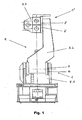
- the Fig. 1 shows a multi-axis industrial robot R in back view. At least in its joint areas between frame R.1 and rocker R.2 or rocker and arm R.3, the robot R has a gear 1, 1 'with relatively rotatable parts 2, 3 and 2', 3 '.
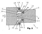
- the Fig. 2 shows a schematic sectional view of a transmission 1 with a first part 2 and a second part 3, which are rotatable relative to each other about an axis A of the transmission 1 (arrow P in Fig. 2 ).
- the parts 2, 3 shown can be, for example, a transmission housing 2 and a drive or output shaft 3 in a multi-axis industrial robot (not shown).
- the first part 2 has on its part 3 facing the end face 2.1 a first recess 2.2 and a second recess 2.3, with which corresponding complementary first and second projections 3.1, 3.2 at an end face 3.3 of the second part 3 are engaged. Furthermore, according to the Fig.
- the first projection 3.1 and the first recess 2.2 have a substantially circular-cylindrical shape, while the second projection 3.2 and the second recess 2.3 are substantially annular.
- the second projection 3.2 and the second recess 2.3 surround the first projection 3.1 and the first recess 2.2 each concentric with respect to the axis A.
- a first annular seal 4 is arranged between an outer boundary surface 3.4 of the first projection 3.1 and an inner boundary surface 2.4 of the first recess 2.2.
- a second, likewise annular seal 5 is arranged between an inner boundary surface 2.5 of the second recess 2.3 and an outer boundary surface 3.5 of the second projection 3.2.
- the first projection 3.1 and the first recess 2.2 have a substantially circular-cylindrical shape, while the second projection 3.2 and the second recess 2.3 are substantially annular.
- the second projection 3.2 and the second recess 2.3 surround the first projection 3.1 and the first recess 2.2 each concentrically with respect to the axis A. Furthermore, the Fig. 2 removable, that between the seals 4, 5 a substantially completed gap space 6 is formed, which has an approximately S-shaped cross-section in the case of the specific embodiment shown and arrangement of the projections 3.1, 3.2 and recesses 2.2, 2.3.
- the inner seal 4 may be a conventional transmission seal known to the person skilled in the art.
- the additionally provided, outer seal 5 is preferably formed in a food-grade material, for example in PTFE, EPDM, POM or fluoroelastomer.
- the inner seal 4 retains a transmission lubricant and thus prevents contamination of the environment, while the outer seal 5 prevents ingress of water and dirt into the transmission 1.
- the gap between the seals 4, 5 6 supports both seals, while in the event of failure of one of the seals 4, 5, the other takes over their protective function.
- the thus created gear 1 is thus suitable due to its special seal assembly 4, 5 in particular for use in the food processing industry.
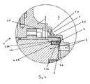
- Fig. 3 to 6 show in detail concrete further embodiments of the transmission, wherein for comparison with the schematic representation of Fig. 2 corresponding components are provided with the same reference numerals.
- the outer seal 5 is formed as a simple circumferential sealing lip 5.1, which is concavely curved against an outer space 7, for example, a working space of a robot that is generally prevented emergence of dirt spaces, and at the outer boundary surface 3.5 of the second Part 3 of the transmission 1 is applied.
- the sealing lip 5.1 is in accordance with Fig. 3 between an inner boundary surface 2.5 of the outer recess 2.3 and arranged in the recess 2.3 annular insert means 2.6 and held by means disposed in a circumferential groove 2.6a of the insert means 2.6 annular retaining means 2.7.
- the inner seal 4 is the subject of the Fig. 3 formed as an annular seal having a substantially U-shaped profile and arranged such that it has on its side facing away from the gap 6 side 4.1 a concave profile, are avoided by the dirt spaces.
- the outer seal 5 is formed with two substantially mutually parallel sealing lips 5.1, 5.1 'and without resources 2.6 ( Fig. 3 ) is disposed between the first part 2 and the second part 3.
- the inner seal 4 has in the course of this embodiment, a double U-shaped profile, wherein free leg 4.2ad the inner seal 4 are arranged such that this on both the gap space 6 side facing as well as on its side facing away from the gap 6 4.1 or 4.2 has a concave profile.
- the insert means 2.6 is not integrally formed, but provided in the region of its outer end face 2.6b with an annular, wedge-shaped in cross-section extension piece 2.6c, via which the curvature of the sealing lip 5.1 is adjustable.
- the insert means 2.6 is not integrally formed, but provided in the region of its outer end face 2.6b with an annular, wedge-shaped in cross-section extension piece 2.6c, via which the curvature of the sealing lip 5.1 is adjustable.
- Fig. 5 as well as in Fig. 6 not all reference signs are registered (cf. Fig. 3 . 4 ).
- the Fig. 6 essentially shows one of Fig. 3 corresponding transmission 1, but with an inner seal 4 according to the Fig. 4 ,
Landscapes
- Engineering & Computer Science (AREA)
- Robotics (AREA)
- Mechanical Engineering (AREA)
- Manipulator (AREA)
- Sealing Of Bearings (AREA)
- Sealing Devices (AREA)
Claims (12)
- Robot industriel à axes multiples, présentant un engrenage avec au moins deux parties (2, 3) rotatives l'une par rapport à l'autre, deux joints (4, 5) au moins étant placés entre les pièces (2, 3) rotatives l'une par rapport à l'autre, un des joints (5) étant formé par une lèvre d'étanchéité (5.1, 5.1') en cuvette contre une zone extérieure (7) et apposée depuis l'extérieur contre une des pièces (3), et la première pièce (2) présentant sur sa face frontale (2.1) tournée vers la deuxième pièce (3) un premier creux (2.2) et un deuxième creux (2.3) dans lesquels sont en prise des première et deuxième saillies (3.1., 3.2) complémentaires correspondantes de la deuxième pièce (3), et l'un des joints (4) étant placé entre une périphérie (3.4) de la première saillie (3.1) et une périphérie (3.4) du premier creux (2.2) et l'autre joint (5) étant placé entre des périphéries (2.5, 3.5) du deuxième creux (2.3) et de la deuxième saillie (3.2).
- Robot industriel à axes multiples selon la revendication 1, caractérisé en ce que les joints (4,5) sont réalisés de forme sensiblement annulaire.
- Robot industriel à axes multiples selon la revendication 2, caractérisé en ce que les joints (4, 5) sont agencés de manière concentrique.
- Robot industriel à axes multiples selon l'une des revendications 1 à 3, caractérisé en ce que la première saillie (3.1) et le premier creux (2.2) présentent une forme sensiblement cylindrique circulaire.
- Robot industriel à axes multiples selon l'une des revendications 1 à 4, caractérisé en ce que la deuxième saillie (3.2) et le deuxième creux (2.3) sont réalisés de forme sensiblement annulaire.
- Robot industriel à axes multiples selon l'une des revendications 1 à 5, caractérisé en ce que la deuxième saillie (3.2) et le deuxième creux (2.3) entourent de manière concentrique la première saillie (3.1) et le premier creux (2.2) respectivement.
- Robot industriel à axes multiples selon l'une des revendications 1 à 6, caractérisé en ce qu'entre les joints (4, 5) est formé un interstice (6) sensiblement fermé.
- Robot industriel à axes multiples selon l'une des revendications 1 à 7, caractérisé en ce qu'au moins l'autre joint (5) est réalisée de manière à éviter des espaces d'encrassement.
- Robot industriel à axes multiples selon les revendications 7 ou 8, caractérisé en ce qu'un des joints (4) présente au moins sur sa face (4.1) détournée de l'interstice (6) un profil concave.
- Robot industriel à axes multiples selon l'une des revendications 1 à 9, caractérisé en ce qu'au moins un des joints (4, 5) est réalisés en polytétrafluoroéthylène (PTFE), en éthylène-propylène-diène-caoutchouc (EPDM) en polyoxyméthylène (PCM) ou en fluorélastomère.
- Robot industriel à axes multiples selon l'une des revendications 1 à 10, caractérisé en ce que l'interstice (6) est sollicité par de la pression.
- Robot industriel à axes multiples selon l'une des revendications précédentes, caractérisé en ce qu'une (2) des pièces (2, 3) rotatives l'une par rapport à l'autre est réalisée en tant que carter pour le l'engrenage, et en ce que l'autre pièce (3) sort de la partie formant carter (2), en particulier sous forme d'un arbre d'entraînement ou de sortie.
Applications Claiming Priority (2)
| Application Number | Priority Date | Filing Date | Title |
|---|---|---|---|
| DE10348841 | 2003-10-21 | ||
| DE10348841A DE10348841B4 (de) | 2003-10-21 | 2003-10-21 | Vorrichtung mit relativ zueinander drehbaren Teilen und einer Dichtungsanordnung |
Publications (3)
| Publication Number | Publication Date |
|---|---|
| EP1525956A1 EP1525956A1 (fr) | 2005-04-27 |
| EP1525956B1 EP1525956B1 (fr) | 2008-12-10 |
| EP1525956B2 true EP1525956B2 (fr) | 2013-01-16 |
Family
ID=34384387
Family Applications (1)
| Application Number | Title | Priority Date | Filing Date |
|---|---|---|---|
| EP04024590A Expired - Lifetime EP1525956B2 (fr) | 2003-10-21 | 2004-10-15 | Dispositif avec des éléments rotatifs et un agencement pour l'étanchéité |
Country Status (3)
| Country | Link |
|---|---|
| US (1) | US20050111940A1 (fr) |
| EP (1) | EP1525956B2 (fr) |
| DE (2) | DE10348841B4 (fr) |
Families Citing this family (18)
| Publication number | Priority date | Publication date | Assignee | Title |
|---|---|---|---|---|
| JP2008055560A (ja) | 2006-08-31 | 2008-03-13 | Fanuc Ltd | ロボットの関節部の密封装置及び関節ロボット |
| EP2812163B9 (fr) | 2012-02-08 | 2025-06-18 | Vanrx Pharmasystems Inc. | Appareil et système à bras articulé |
| DE102014226144A1 (de) | 2014-12-16 | 2016-06-16 | Kuka Roboter Gmbh | Industrieroboter und Verfahren zum Bewegen eines Roboterarms in einem Reinraum |
| JP6506227B2 (ja) * | 2016-08-31 | 2019-04-24 | ファナック株式会社 | 関節構造およびロボット |
| CN108127687B (zh) * | 2018-01-29 | 2024-08-30 | 埃夫特智能装备股份有限公司 | 一种工业用机器人手腕 |
| US11312006B2 (en) * | 2018-03-30 | 2022-04-26 | Fanuc Corporation | Robot drive unit and robot |
| DE102018205297A1 (de) | 2018-04-09 | 2019-10-10 | Osram Gmbh | Roboterarmteil mit einer Desinfektionseinrichtung |
| EP3941688B1 (fr) | 2019-03-22 | 2025-01-01 | ABB Schweiz AG | Arrangement d'étanchéité pour une articulation de robot |
| IT202000008974A1 (it) * | 2020-04-24 | 2021-10-24 | Romaco Srl | Apparecchiatura per il riempimento di contenitori con un materiale in polvere |
| CN116783042B (zh) * | 2021-01-27 | 2025-09-16 | 发那科株式会社 | 关节结构以及机器人 |
| EP4330567A4 (fr) * | 2021-04-30 | 2024-12-18 | Abb Schweiz Ag | Ensemble d'étanchéité et robot |
| CN114311015B (zh) * | 2022-02-16 | 2024-11-22 | 深圳市越疆科技有限公司 | 关节模组的密封结构、关节模组、机械臂和机器人 |
| DE102022108882A1 (de) * | 2022-04-12 | 2023-10-12 | Schock Gmbh | Gießform zur Herstellung eines eine Vorder- und eine Rückseite aufweisenden Gießkörpers aus einer aushärtbaren Gießmasse |
| CN114855903B (zh) * | 2022-04-29 | 2023-07-25 | 三一重机有限公司 | 属具与作业臂的连接结构及作业机械 |
| DE102022205077A1 (de) | 2022-05-20 | 2023-11-23 | Kuka Deutschland Gmbh | Abdichtung eines Radialspalts zwischen zwei Glieder eines Roboterarms |
| JP2024033532A (ja) * | 2022-08-30 | 2024-03-13 | 住友重機械工業株式会社 | 動力伝達装置、ロボット |
| EP4481243A1 (fr) | 2023-06-22 | 2024-12-25 | YASKAWA Europe GmbH | Robot |
| CN118721285B (zh) * | 2024-09-04 | 2024-11-19 | 楚天科技股份有限公司 | 一种洁净机器人关节密封结构、洁净机器人关节及洁净机器人 |
Citations (1)
| Publication number | Priority date | Publication date | Assignee | Title |
|---|---|---|---|---|
| JPH0584691A (ja) † | 1991-09-25 | 1993-04-06 | Shin Meiwa Ind Co Ltd | 真空チヤンバ用産業ロボツト装置 |
Family Cites Families (14)
| Publication number | Priority date | Publication date | Assignee | Title |
|---|---|---|---|---|
| FR2016621A1 (fr) * | 1968-08-30 | 1970-05-08 | Goeppner Kaiserslautern Eisen | |
| US3547455A (en) * | 1969-05-02 | 1970-12-15 | Gen Electric | Rotary seal including organic abradable material |
| CH547455A (de) * | 1972-04-18 | 1974-03-29 | Ciba Geigy Ag | Wellendichtung. |
| DE2908713C2 (de) * | 1979-03-06 | 1985-04-18 | Skf Kugellagerfabriken Gmbh, 8720 Schweinfurt | Abdichtung für Lagerbüchsen |
| SE8605070L (sv) * | 1986-11-26 | 1988-05-27 | Komatsu Mfg Co Ltd | Bojlig robotarm |
| US4717161A (en) * | 1987-04-27 | 1988-01-05 | A. W. Chesterton Company | Multiple-lip seal for cylinder rod and the like |
| US4900039A (en) * | 1988-07-27 | 1990-02-13 | The Pullman Company | Twin face seal |
| DE3833690A1 (de) * | 1988-10-04 | 1990-04-12 | Acla Werke Gmbh | Radialwellendichtung |
| JP3656916B2 (ja) * | 1994-12-07 | 2005-06-08 | 株式会社安川電機 | 回転部のシール装置、および回転部にシール装置を備えた産業用ロボット |
| US5676472A (en) * | 1995-07-10 | 1997-10-14 | Smart Machines | Rotary labyrinth seal |
| JPH11221789A (ja) * | 1998-02-06 | 1999-08-17 | Fanuc Ltd | 産業用ロボットの密封構造 |
| US6196551B1 (en) * | 1998-09-08 | 2001-03-06 | General Motors Corporation | Radial lip seal with integral splash lip |
| US6568899B1 (en) * | 1999-11-30 | 2003-05-27 | Wafermasters, Inc. | Wafer processing system including a robot |
| US20030006563A1 (en) * | 2001-06-20 | 2003-01-09 | Cater Brian B. | Rotary facial seal and bearing assembly with plastic ring |
-
2003
- 2003-10-21 DE DE10348841A patent/DE10348841B4/de not_active Expired - Lifetime
-
2004
- 2004-10-15 DE DE502004008628T patent/DE502004008628D1/de not_active Expired - Fee Related
- 2004-10-15 EP EP04024590A patent/EP1525956B2/fr not_active Expired - Lifetime
- 2004-10-20 US US10/969,685 patent/US20050111940A1/en not_active Abandoned
Patent Citations (1)
| Publication number | Priority date | Publication date | Assignee | Title |
|---|---|---|---|---|
| JPH0584691A (ja) † | 1991-09-25 | 1993-04-06 | Shin Meiwa Ind Co Ltd | 真空チヤンバ用産業ロボツト装置 |
Also Published As
| Publication number | Publication date |
|---|---|
| DE10348841A1 (de) | 2005-06-02 |
| EP1525956A1 (fr) | 2005-04-27 |
| DE502004008628D1 (de) | 2009-01-22 |
| US20050111940A1 (en) | 2005-05-26 |
| EP1525956B1 (fr) | 2008-12-10 |
| DE10348841B4 (de) | 2005-12-15 |
Similar Documents
| Publication | Publication Date | Title |
|---|---|---|
| EP1525956B1 (fr) | Dispositif avec des éléments rotatifs et un agencement pour l'étanchéité | |
| DE10325254B4 (de) | Montageschutzring | |
| DE3602500C2 (fr) | ||
| DE2709394C2 (de) | Wellendichtung | |
| DE3404816C2 (de) | Dichtungseinrichtung | |
| DE102016204007A1 (de) | Dichtung | |
| EP2049419B1 (fr) | Convoyeur de galerie avec élément de palier | |
| EP1132642B1 (fr) | Support en gomme | |
| EP3728910B1 (fr) | Système d'étanchéité | |
| DE112015005286T5 (de) | Dichtungsvorrichtung und Zahnradgetriebevorrichtung | |
| WO2013093900A1 (fr) | Joint de fente en forme de mâchoire ou de griffe | |
| DE10315850A1 (de) | Kombinationsdichtung | |
| DE102010024289A1 (de) | Gleitringdichtung | |
| DE102012206892A1 (de) | Wälzlager mit Dichtscheibe | |
| DE102019204877A1 (de) | Dichtungsstruktur und diese Dichtungsstruktur aufweisende Vorrichtung | |
| EP1323958A1 (fr) | Joint d'étanchéité | |
| DE19740822A1 (de) | Dichtring | |
| DE2728506A1 (de) | Abgedichtetes gleiskettengelenk | |
| DE102009055647A1 (de) | Kassettendichtungen für Radiallager und Installationsverfahren | |
| DE102019205338A1 (de) | Spannungswellengetriebe | |
| DE2733161C3 (de) | Dichtungskörper zur Verwendung in einer Bohrung und Verfahren zu seiner Herstellung | |
| EP0408827B1 (fr) | Fixation d'un joint dans un alésage d'un organe de machine | |
| DE10042834B4 (de) | Kassettendichtung | |
| DE102014213993A1 (de) | Flanschanordnung sowie Fahrwerksaktuator umfassend eine solche Flanschanordnung | |
| DE10064216B4 (de) | Radialwellendichtung |
Legal Events
| Date | Code | Title | Description |
|---|---|---|---|
| PUAI | Public reference made under article 153(3) epc to a published international application that has entered the european phase |
Free format text: ORIGINAL CODE: 0009012 |
|
| 17P | Request for examination filed |
Effective date: 20050226 |
|
| AK | Designated contracting states |
Kind code of ref document: A1 Designated state(s): AT BE BG CH CY CZ DE DK EE ES FI FR GB GR HU IE IT LI LU MC NL PL PT RO SE SI SK TR |
|
| AX | Request for extension of the european patent |
Extension state: AL HR LT LV MK |
|
| AKX | Designation fees paid |
Designated state(s): DE FR GB IT SE |
|
| 17Q | First examination report despatched |
Effective date: 20061129 |
|
| GRAP | Despatch of communication of intention to grant a patent |
Free format text: ORIGINAL CODE: EPIDOSNIGR1 |
|
| GRAS | Grant fee paid |
Free format text: ORIGINAL CODE: EPIDOSNIGR3 |
|
| GRAS | Grant fee paid |
Free format text: ORIGINAL CODE: EPIDOSNIGR3 |
|
| GRAA | (expected) grant |
Free format text: ORIGINAL CODE: 0009210 |
|
| AK | Designated contracting states |
Kind code of ref document: B1 Designated state(s): DE FR GB IT SE |
|
| REG | Reference to a national code |
Ref country code: GB Ref legal event code: FG4D Free format text: NOT ENGLISH |
|
| REF | Corresponds to: |
Ref document number: 502004008628 Country of ref document: DE Date of ref document: 20090122 Kind code of ref document: P |
|
| REG | Reference to a national code |
Ref country code: SE Ref legal event code: TRGR |
|
| PLBI | Opposition filed |
Free format text: ORIGINAL CODE: 0009260 |
|
| PLAX | Notice of opposition and request to file observation + time limit sent |
Free format text: ORIGINAL CODE: EPIDOSNOBS2 |
|
| 26 | Opposition filed |
Opponent name: ABB AB Effective date: 20090908 |
|
| PLBB | Reply of patent proprietor to notice(s) of opposition received |
Free format text: ORIGINAL CODE: EPIDOSNOBS3 |
|
| PG25 | Lapsed in a contracting state [announced via postgrant information from national office to epo] |
Ref country code: DE Free format text: LAPSE BECAUSE OF NON-PAYMENT OF DUE FEES Effective date: 20100501 |
|
| PG25 | Lapsed in a contracting state [announced via postgrant information from national office to epo] |
Ref country code: GB Free format text: LAPSE BECAUSE OF NON-PAYMENT OF DUE FEES Effective date: 20091015 |
|
| PG25 | Lapsed in a contracting state [announced via postgrant information from national office to epo] |
Ref country code: IT Free format text: LAPSE BECAUSE OF NON-PAYMENT OF DUE FEES Effective date: 20091015 |
|
| PLAB | Opposition data, opponent's data or that of the opponent's representative modified |
Free format text: ORIGINAL CODE: 0009299OPPO |
|
| R26 | Opposition filed (corrected) |
Opponent name: ABB AB Effective date: 20090908 |
|
| PLAB | Opposition data, opponent's data or that of the opponent's representative modified |
Free format text: ORIGINAL CODE: 0009299OPPO |
|
| R26 | Opposition filed (corrected) |
Opponent name: ABB AB Effective date: 20090908 |
|
| PUAH | Patent maintained in amended form |
Free format text: ORIGINAL CODE: 0009272 |
|
| STAA | Information on the status of an ep patent application or granted ep patent |
Free format text: STATUS: PATENT MAINTAINED AS AMENDED |
|
| 27A | Patent maintained in amended form |
Effective date: 20130116 |
|
| AK | Designated contracting states |
Kind code of ref document: B2 Designated state(s): DE FR GB IT SE |
|
| REG | Reference to a national code |
Ref country code: DE Ref legal event code: R102 Ref document number: 502004008628 Country of ref document: DE Effective date: 20130116 |
|
| REG | Reference to a national code |
Ref country code: SE Ref legal event code: RPEO |
|
| REG | Reference to a national code |
Ref country code: FR Ref legal event code: PLFP Year of fee payment: 13 |
|
| REG | Reference to a national code |
Ref country code: FR Ref legal event code: PLFP Year of fee payment: 14 |
|
| REG | Reference to a national code |
Ref country code: FR Ref legal event code: PLFP Year of fee payment: 15 |
|
| P01 | Opt-out of the competence of the unified patent court (upc) registered |
Effective date: 20230528 |
|
| PGFP | Annual fee paid to national office [announced via postgrant information from national office to epo] |
Ref country code: SE Payment date: 20231127 Year of fee payment: 20 Ref country code: FR Payment date: 20231228 Year of fee payment: 20 |
|
| REG | Reference to a national code |
Ref country code: SE Ref legal event code: EUG |