EP1525964A2 - Spitzbohrwerkzeug - Google Patents
Spitzbohrwerkzeug Download PDFInfo
- Publication number
- EP1525964A2 EP1525964A2 EP04256433A EP04256433A EP1525964A2 EP 1525964 A2 EP1525964 A2 EP 1525964A2 EP 04256433 A EP04256433 A EP 04256433A EP 04256433 A EP04256433 A EP 04256433A EP 1525964 A2 EP1525964 A2 EP 1525964A2
- Authority
- EP
- European Patent Office
- Prior art keywords
- spade bit
- spade
- blade portion
- diameter
- bit
- Prior art date
- Legal status (The legal status is an assumption and is not a legal conclusion. Google has not performed a legal analysis and makes no representation as to the accuracy of the status listed.)
- Withdrawn
Links
- 238000005520 cutting process Methods 0.000 claims abstract description 51
- 238000005553 drilling Methods 0.000 abstract description 24
- 230000035515 penetration Effects 0.000 abstract description 3
- 238000004140 cleaning Methods 0.000 abstract description 2
- 239000002023 wood Substances 0.000 description 28
- 238000012360 testing method Methods 0.000 description 14
- 230000008901 benefit Effects 0.000 description 9
- 229920002522 Wood fibre Polymers 0.000 description 7
- 239000002025 wood fiber Substances 0.000 description 7
- 238000007790 scraping Methods 0.000 description 6
- 230000006872 improvement Effects 0.000 description 5
- 239000000463 material Substances 0.000 description 4
- 238000013461 design Methods 0.000 description 2
- 238000004519 manufacturing process Methods 0.000 description 2
- 229920000535 Tan II Polymers 0.000 description 1
- 230000009471 action Effects 0.000 description 1
- 238000010960 commercial process Methods 0.000 description 1
- 238000010276 construction Methods 0.000 description 1
- 238000012937 correction Methods 0.000 description 1
- 238000012986 modification Methods 0.000 description 1
- 230000004048 modification Effects 0.000 description 1
- 230000008520 organization Effects 0.000 description 1
- 230000000149 penetrating effect Effects 0.000 description 1
- 238000009428 plumbing Methods 0.000 description 1
Images


Classifications
-
- B—PERFORMING OPERATIONS; TRANSPORTING
- B23—MACHINE TOOLS; METAL-WORKING NOT OTHERWISE PROVIDED FOR
- B23B—TURNING; BORING
- B23B51/00—Tools for drilling machines
- B23B51/0002—Drills with connected cutting heads, e.g. with non-exchangeable cutting heads; Drills with a single insert extending across the rotational axis and having at least two radially extending cutting edges in the working position
- B23B51/0003—Drills with connected cutting heads, e.g. with non-exchangeable cutting heads; Drills with a single insert extending across the rotational axis and having at least two radially extending cutting edges in the working position with exchangeable heads or inserts
- B23B51/00035—Spade drills
-
- B—PERFORMING OPERATIONS; TRANSPORTING
- B27—WORKING OR PRESERVING WOOD OR SIMILAR MATERIAL; NAILING OR STAPLING MACHINES IN GENERAL
- B27G—ACCESSORY MACHINES OR APPARATUS FOR WORKING WOOD OR SIMILAR MATERIALS; TOOLS FOR WORKING WOOD OR SIMILAR MATERIALS; SAFETY DEVICES FOR WOOD WORKING MACHINES OR TOOLS
- B27G15/00—Boring or turning tools; Augers
-
- B—PERFORMING OPERATIONS; TRANSPORTING
- B23—MACHINE TOOLS; METAL-WORKING NOT OTHERWISE PROVIDED FOR
- B23B—TURNING; BORING
- B23B2251/00—Details of tools for drilling machines
- B23B2251/14—Configuration of the cutting part, i.e. the main cutting edges
-
- B—PERFORMING OPERATIONS; TRANSPORTING
- B23—MACHINE TOOLS; METAL-WORKING NOT OTHERWISE PROVIDED FOR
- B23B—TURNING; BORING
- B23B2251/00—Details of tools for drilling machines
- B23B2251/24—Overall form of drilling tools
- B23B2251/248—Drills in which the outer surface is of special form
-
- B—PERFORMING OPERATIONS; TRANSPORTING
- B23—MACHINE TOOLS; METAL-WORKING NOT OTHERWISE PROVIDED FOR
- B23B—TURNING; BORING
- B23B2251/00—Details of tools for drilling machines
- B23B2251/40—Flutes, i.e. chip conveying grooves
- B23B2251/406—Flutes, i.e. chip conveying grooves of special form not otherwise provided for
-
- Y—GENERAL TAGGING OF NEW TECHNOLOGICAL DEVELOPMENTS; GENERAL TAGGING OF CROSS-SECTIONAL TECHNOLOGIES SPANNING OVER SEVERAL SECTIONS OF THE IPC; TECHNICAL SUBJECTS COVERED BY FORMER USPC CROSS-REFERENCE ART COLLECTIONS [XRACs] AND DIGESTS
- Y10—TECHNICAL SUBJECTS COVERED BY FORMER USPC
- Y10T—TECHNICAL SUBJECTS COVERED BY FORMER US CLASSIFICATION
- Y10T408/00—Cutting by use of rotating axially moving tool
- Y10T408/89—Tool or Tool with support
- Y10T408/905—Having stepped cutting edges
- Y10T408/906—Axially spaced
- Y10T408/9065—Axially spaced with central lead
-
- Y—GENERAL TAGGING OF NEW TECHNOLOGICAL DEVELOPMENTS; GENERAL TAGGING OF CROSS-SECTIONAL TECHNOLOGIES SPANNING OVER SEVERAL SECTIONS OF THE IPC; TECHNICAL SUBJECTS COVERED BY FORMER USPC CROSS-REFERENCE ART COLLECTIONS [XRACs] AND DIGESTS
- Y10—TECHNICAL SUBJECTS COVERED BY FORMER USPC
- Y10T—TECHNICAL SUBJECTS COVERED BY FORMER US CLASSIFICATION
- Y10T408/00—Cutting by use of rotating axially moving tool
- Y10T408/89—Tool or Tool with support
- Y10T408/909—Having peripherally spaced cutting edges
Definitions
- the present invention relates to a spade bit.
- Spade bits are generally flat, inexpensive bits having a thickness of generally between 17/200" and 19/200", which are commonly used in the construction trade for making clearance holes for electrical and plumbing purposes. Spade bits are also commonly used for drilling bolt holes in deck timbers (4 X 4 and 6 X 6).
- spade bits require more axial pressure than a twist drill. Also, as the spade bit begins to get dull, the user must apply more pressure to get the bit to cut chips. The axial force requirement also increases as the depth of the hole increases. Further, the flat spade bit has a tendency to vibrate and shake as it works. The high axial force requirement causes much of the vibration to be transmitted to the user. Another shortcoming of the spade bit is that since considerable axial force is applied, there is a potential for mishap when the hole is completed. The operator must brace himself to maintain balance when the hole is completed. It is not uncommon for the user to bust his/her knuckles against the workpiece.
- spade bits are different than wood boring tools because the manufacturing of spade bits does not involve any lathe or turning operations.
- Wood boring tools typically have helical threads or circular grooves thereon for providing improved pull through of the wood boring tool.
- a primary object of the invention is to improve the ease of using an inexpensive spade bit by adding a feature to make it pull through the work piece like an auger bit.
- Another primary object of the invention is to provide a self-feeding spade bit which is easy and fast to use.
- a further object of the invention is to provide a spade bit which cleans the hole and permits easy removal of the spade bit from the hole after drilling.
- Still another object of the invention is to provide a spade bit which does not require more axial pressure than a twist drill.
- Another object of the invention is to provide a spade bit which does not require the user to apply more pressure to get the spade bit to cut chips than prior art spade bits.
- Yet another object of the invention is to provide a spade bit in which the axial force requirement does not increase as the depth of the hole increases.
- Still another object of the invention is to provide a spade bit which reduces the tendency of the spade bit to vibrate and shake as it works, such that the amount of vibration transferred to the user is minimized.
- Another object of the invention is to provide a self-feeding spade bit such that an operator need not apply any axial force to complete the hole.
- Still another object of the invention is to provide a spade bit which reduces the chance of the operator injuring himself/herself while using the spade bit to create a hole.
- Yet another object of the invention is to provide a spade bit which is inexpensive to manufacture.
- the invention provides a spade bit having straight grooves at a lead angle of 4 to 8 degrees, preferably 6 degrees, placed on flat edges of the spade bit.
- a spade bit is provided having two steps of straight grooves at a lead angle of 4 to 8 degrees placed on flat edges of the spade bit.
- a spade bit is provided having straight grooves at a lead angle of 4 to 8 degrees placed on flat, tapered edges of the spade bit.
- the straight grooves on the flat edges of the spade bits allow the spade bit to pull itself through the workpiece with a minimal amount of penetration.
- the flat edges of the spade bit may also have cutting surfaces for cleaning the hole and permitting the easy removal of the spade bit from the hole after drilling.
- a first embodiment of a spade bit 100 which incorporates features of the invention is shown in FIGURES 1 and 2 with reference numerals being in the one hundreds.
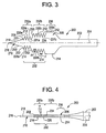
- a second embodiment of a spade bit 200 which incorporates features of the invention is shown in FIGURES 3 and 4 with reference numerals being in the two hundreds.
- a third embodiment of a spade bit 300 which incorporates features of the invention is shown in FIGURES 5 and 6 with reference numerals being in the three hundreds.
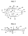
- a fourth embodiment of a spade bit 400 which incorporates features of the invention is shown in FIGURES 7 and 8 with reference numerals being in the four hundreds.
- the spade bit 100, 200, 300, 400 is used to form a hole in a workpiece (not shown) by drilling.
- the spade bit 100 includes an elongated shaft 102 which defines a longitudinal axis 104.
- a generally flat, generally rectangular blade portion 106 is joined to a forward end of the shaft 102.
- a rear end (not shown) of the shaft 102, opposite the forward end, is received and held by a drill (not shown) during drilling operations.
- a forward end 108 of the blade portion 106, opposite the forward end of the shaft 102, has a spur 110 which extends therefrom.
- the spur 110 is provided equidistant between a first side edge 112 of the blade portion 106 and a second side edge 114 of the blade portion 106.
- the first and second side edges 112, 114 are generally parallel to one another.
- the spur 110 is used to center and to guide the spade bit 100 during drilling operations.
- the spur 110 is generally of a triangular or pyramidal configuration such that it comes to a point 116.
- the spur 110 also includes cutting edges 118 for removing wood or other material when the spade bit 100 is rotated in a predetermined direction of rotation during drilling operations.
- the spur cutting edges 118 extend along opposed sides of the base of the spur 110 at the forward end 108 to the forwardmost portion of the spur 110, i.e., the spur point 116.
- a cutting edge 120 is formed on the forward end 108 between the spur 110 and the first side edge 112.
- the cutting edge 120 is generally perpendicular to the first side edge 112.
- a cutting edge 122 is formed on the forward end 108 between the spur 110 and the second side edge 114.
- the cutting edge 120 is generally perpendicular to the second side edge 114.
- the cutting edges 120, 122 of the spade bit 100 are the leading surfaces of the blade portion 106 and function to enlarge the hole of the workpiece.
- the first side edge 112 and the second side edge 114 extend between a first face 124 of the blade portion 106 and a second face 126 of the blade portion 106 to define a thickness of the blade portion 106:
- the first and second faces 124, 126 are parallel to one another and are generally approximately between 17/200" and 19/200" apart from one another, such that the blade portion 106 is generally approximately between 17/200" and 19/200" thick.
- the blade portion 106 is approximately 3/32" thick.
- the spade bit 100 is much thinner than other wood boring bits which typically have a thickness of between 1/4" to 3/10".
- a diameter of the blade portion 106 is defined by the distance between the first side edge 112 and the second side edge 114.
- the first and second faces 124, 126 have two separate portions 132, 136 provided thereon such that the blade portion 106 has two different diameters, with the portion 136 having the larger diameter of the two portions 132, 136.
- the portion 136 can have varying diameters depending on the size of hole to be drilled in the workpiece, but should have a diameter which is larger than a diameter of the first portion 132.
- a forward end of the first portion 132 is provided at the forward end 108 such that it extends from the spur 110.
- the first portion 132 is provided with grooves 128 which have been ground into the edges 112, 114 such that the first portion 132 is a grooved portion of the blade portion 106.
- Each groove 128 is defined by a pair of adjacent crests 129 and a root 131 provided therebetween.
- Each groove 128 is a straight groove, as opposed to a circular or helical groove, because the side edges 112, 114 of the first portion 132 are linear, rather than curved, between the crests 129 and the root 131.
- the straight grooves 128 are ground into the edges at a lead angle ⁇ , see FIGURE 2, wherein the lead angle ⁇ is preferably between 4 and 8 degrees, with a preferred lead angle ⁇ of 6 degrees.
- the preferred lead angle ⁇ of between 4 and 8 degrees was determined after a number of tests.
- wood boring tools which have threads on the outer diameters thereof.
- Each of these tools are relatively massive with a thick cross-section of approximately 1/4" to 3/10
- typical commercial spade bits typically have a cross-section in the range of approximately 17/200" to 19/200" thick, and preferably have a cross-section of approximately 3/32" thick.
- grooves or threads on the edges of the spade bit would not work because there was not enough cross-section. Applicant is not aware of any prior art spade bits which have grooves or threads of any kind on the edges thereof.
- a standard spade bit was used to drill a hole in a 2" by 4" wood workpiece and the chip thickness was measured at approximately 1/32" to 1/16".
- a 1/16" pitch on a 7/8" diameter spade bit is equal to a lead angle of 1.25 degrees.
- a thread would advance just 0.004".
- a spade bit was made using a 2 degree angle.
- the spade bit, using the 2 degree angle, did not produce any noticeable self-feeding characteristics.
- the height H of the grooves 128 is preferably 0.14 inches and the grooves 128 generally do not extend to the cutting edges 120, 122.
- the height H of the grooves 128 is defined as the distance from one root 131 to a midpoint of a straight line connecting the two crests 129 which are adjacent to the one root 131.
- the pitch P of the grooves is preferably 0.10".
- the pitch P of the grooves 128 is defined as the distance from one crest 129 to an adjacent crest 129.
- the straight grooves 128 provided on the first and second edges 112, 114 of the spade bit 100 provide benefits to the spade bit 100 in comparison to a standard spade bit which does not have the straight grooves provided on its edges. Namely, the spade bit 100 pulls through the workpiece more easily such that the operator need only apply minimal, if any, axial force in order to complete the hole. Because the operator no longer has to lean into the workpiece to make the drill work, there is less tendency for the operator to hit/bust his knuckles on the work piece when the drill breaks through. As the spade bit 100 is self-feeding, it is much easier and faster to use than standard spade bits. The spade bit 100 also provides many of the benefits of a wood boring tool, but the cost of the spade bit 100 is still commensurate with a standard spade bit.
- the second portion 136 is provided at a rear end of the first portion 132 such that it extends between the first portion 132 and the shaft 102.
- the side edges 112, 114 of the second portion 136 are not ground to have grooves formed therein, but rather are sharpened such that the side edges 112, 114 of the second portion 136 act as cutting edges.
- the second portion 136 has a diameter from the first side edge 112 to the second side edge 114 of 0.875", as the spade bit 100 is a 7/8" diameter spade bit.
- the diameter of the second portion 136 is larger than the diameter of the first portion 132 .
- the second portion 136 is provided in order to improve the ease of removing the spade bit 100 from the workpiece after drilling the hole relative to a standard spade bit. While making the spade bit 100 pull itself was the primary goal of the tests, early prototype spade bits required significant force to remove them from the workpiece after drilling because the hole was rough and the feeding grooves interfered with the inner diameter of the hole. The spade bit 100 could be easily removed if the electric drill motor were reversed, but this added user operation was undesirable. Also, the spade bit 100 produced a hole with stringy wood fibers from the scraping, slipping and cutting by the grooves 128. Thus, the first and second side edges 112, 114 of the second portion 136 were sharpened to act as cutting edges in order to enlarge the wall of the hole and to clean and smooth the hole by removing these stringy wood fibers from the wall of the hole.
- the second embodiment of the spade bit 200 was derived as an improvement over the first embodiment of the spade bit 100. While the self-feeding of the spade bit 100 was adequate, it was desired to make the spade bit feed itself with less engagement in the workpiece.
- the spade bit 200 includes an elongated shaft 202 which defines a longitudinal axis 204.
- a generally flat blade portion 206 is joined to a forward end of the shaft 202.
- a rear end (not shown) of the shaft 202, opposite the forward end, is received and held by a drill (not shown) during drilling operations.
- a forward end 208 of the blade portion 206, opposite the forward end of the shaft 202, has a spur 210 which extends therefrom.
- the spur 210 is provided between a first side edge 212 of the blade portion 206 and a second side edge 214 of the blade portion 206.
- the first side edge 212 is generally parallel to the second side edge 214.
- the spur 210 is used to center and to guide the spade bit 200 during drilling operations.
- the spur 210 is generally of a triangular or pyramidal configuration such that it comes to a point 216.
- the spur 210 also includes cutting edges 218 for removing wood or other material when the spade bit 200 is rotated in a predetermined direction of rotation during drilling operations.
- the spur cutting edges 218 extend along opposed sides of the base of the spur 210 at the forward end 208 to the forwardmost portion of the spur 210, i.e., the spur point 216.
- the first side edge 212 and the second side edge 214 extend between a first face 224 of the blade portion 206 and a second face 226 of the blade portion 206 to define a thickness of the blade portion 206.
- the first and second faces 224, 226 are parallel to one another and are generally approximately between 17/200" and 19/200" apart from one another, such that the blade portion 206 is generally between approximately 17/200" and 19/200" thick.
- the blade portion 206 is approximately 3/32" thick.
- the spade bit 200 is much thinner than other wood boring bits which typically have a thickness of between 1/4" to 3/10".
- a diameter of the blade portion 206 is defined by the distance between the first side edge 212 and the second side edge 214.
- the first and second faces 224, 226 have two separate portions 232, 236 provided thereon.
- the first portion 232 is divided into two separate sections 232a, 232b such that the blade portion 206 has three different diameters, with the portion 236 having the larger diameter over the first and second sections 232a, 232b of the first portion 232.
- the portion 236 can have varying diameters depending on the size of hole to be drilled in the workpiece, but should have a diameter which is larger than a diameter of the first and second sections 232a, 232b of the first portion 232.
- a forward end of the first section 232a of the first portion 232 is provided at the forward end 208 such that it extends from the spur 210.
- the first section 232a of the first portion 232 is provided with grooves 228a which have been ground onto the edges 212, 214.
- Each groove 228a is defined by a pair of adjacent crests 229a and a root 231a provided therebetween.
- Each groove 228a is a straight groove, as opposed to a circular or helical groove, because the side edges 212, 214 of the first section 232a of the first portion 232 are linear, rather than curved, between the crests 229a and the root 231a.
- the straight grooves 228a are ground into the side edges 212, 214 at a lead angle ⁇ , see FIGURE 4, wherein the lead angle ⁇ is preferably between 4 and 8 degrees, with a preferred lead angle ⁇ of 6 degrees.
- a cutting edge 220 may be formed on the forward end 208 of the blade portion 206 between the spur 210 and the first side edge 212 of the blade portion 206.
- a cutting edge 222 may be formed on the forward end 208 of the blade portion 206 between the spur 210 and the second side edge 214 of the blade portion 206.
- the cutting edges 220, 222 of the spade bit 200 are the leading surfaces of the first section 232a of the first portion 232 and function to enlarge the hole of the workpiece.
- the height H of the grooves 228a is preferably 0.1375" such that the first section 232a of the first portion 232 has an outer diameter from first edge 212 to second edge 214 of 0.5".
- the height H of the grooves 228a is defined as the distance from one root 231a to a midpoint of a straight line connecting the two crests 229a which are adjacent to the one root 231 a.
- the pitch P of the grooves 228a is preferably 0.10".
- the pitch P of the grooves 228a is defined as the distance from one crest 229a to an adjacent crest 229a.
- a forward end of the second section 232b of the first portion 232 is provided at a rear end of the first section 232a of the first portion 232 such that it extends from the first section 232a of the first portion 232.
- the second section 232b of the first portion 232 is provided with grooves 228b which have been ground onto the edges 212, 214.
- Each groove 228b is defined by a pair of adjacent crests 229b and a root 231b provided therebetween.
- Each groove 228b is a straight groove, as opposed to a circular or helical groove, because the side edges 212, 214 of the second section 232b of the first portion 232 are linear, rather than curved, between the crests 229b and the root 231b.
- the straight grooves 228b are ground into the edges at a lead angle ⁇ , wherein the lead angle ⁇ is preferably between 4 and 8 degrees, with a preferred lead angle ⁇ of 6 degrees.
- a cutting edge 235 is formed on the first side edge 212 of the blade portion 206 and connects the first section 232a of the first portion 232 to the second section 232b of the first portion 232.
- a cutting edge 237 is formed on the second side edge 214 of the blade portion 206 and connects the first section 232a of the first portion 232 to the second section 232b of the first portion 232.
- the cutting edges 235, 237 of the spade bit 200 are the leading surfaces of the second section 232b of the first portion 232 and function to enlarge the hole of the workpiece.
- the grooves 228a of the first section 232a of the first portion 232 provide more pulling with less resistive torque.
- the smaller diameter of the first section 232a of the first portion 232 requires less engagement with the workpiece when the spade bit 200 begins pulling itself through.
- the first portion 232 is a grooved portion of the blade portion 206.
- the height H of the grooves 228b is preferably 0.1375" such that the second section 232b of the first portion 232 has an outer diameter from first edge 212 to second edge 214 of 0.75".
- the height H of the grooves 228b is defined as the distance from one root 231b to a midpoint of a straight line connecting the two crests 229b which are adjacent to the one root 231b.
- the pitch P of the grooves 228b is preferably 0.10".
- the pitch P of the grooves 228b is defined as the distance from one crest 229b to an adjacent crest 229b.
- a forward end of the second portion 236 is provided at a rear end of the second section 232b of the first portion 232 such that it extends from the second section 232b of the first portion 232.
- the edges 212, 214 of the second portion 236 are not ground to have grooves formed therein, but rather are sharpened such that the edges 212, 214 of the second portion 236 act as cutting edges.
- the second portion 236 has an outer diameter from first edge 212 to second edge 214 of 0.875", as the spade bit 200 is a 7/8" diameter spade bit.
- the first edge 212 preferably extends a length of 0.322" while the second edge 214 preferably extends a length of 0.372, the difference between the two lengths being accounted for by half of the pitch of the grooves 228a, 228b.
- the second embodiment of the spade bit 200 was derived as an improvement over the first embodiment of the spade bit 100 because it was desired to make the spade bit feed itself with less engagement in the workpiece.
- two steps of grooves (which resulted in 232a and 232b) were placed on each edge 212, 214 of the spade bit 200.
- the smaller steps caused the self-feeding feature to engage with only about 1/4" of the blade portion 206 penetrating the workpiece.
- the grooves 228b on the larger step 232b helped feed the spade bit through the workpiece.
- the prototype in the fifth test was very adequate except for the difficulty in removing the spade bit from the workpiece.
- the two step spade bit 200 was slightly modified such that straight cutting portions were provided at the rear of the blade portion 206 which have larger outer diameters than the two steps of grooves 228a, 228b, similar to the straight cutting portions provided at the rear of the blade portion 106. While making the spade bit 200 pull itself was the primary goal of the tests, early prototype spade bits required significant force to remove them from the workpiece after drilling because the hole was rough and the feeding grooves 228a, 228b interfered with the inner diameter of the hole. The spade bit 200 could be easily removed if the electric drill motor were reversed, but this added user operation was undesirable.
- the side edges 212, 214 of the second portion 236 were sharpened to act as cutting edges in order to enlarge the hole and smooth the wall of the hole.
- the second embodiment of the spade bit 200 is thus the result of the sixth test.
- the spade bit 200 provides the same advantages over the standard spade bit as does the spade bit 100 of the first embodiment, but further provides the advantages of having the spade bit 200 feed itself with less engagement of the blade portion 206 with the work piece, i.e., 1/4" as opposed to 3/4". Further, the spade bit 200 has a distinct step in the first portion 232 of the blade portion 206 as the grooves 228a are provided on the first section 232a of the first portion 232 which has a diameter which is smaller than a diameter of the second section 232b of the first portion 232, where the grooves 228b are provided. As the first section 232a of the first portion 232 has a smaller diameter, the grooves 228a are able to provide more pulling with less resistive torque. The first section 232a of the first portion 232 requires less engagement with the workpiece before the spade bit 200 begins pulling itself through.
- the second portion 236 is again provided in order to improve the ease of removing the spade bit 200 from the workpiece after drilling the hole relative to a standard spade bit. Also, as the spade bit 200 will produce a hole with stringy wood fibers from the scraping, slipping and cutting by the grooves 228a, 228b, the cutting surfaces were added to the second portion 236 to enlarge the hole and to clean and smooth the wall of the hole by removing these stringy wood fibers from the wall of the hole.
- the third embodiment of the spade bit 300 was derived as an improvement over the second embodiment of the spade bit 200.
- the spade bit 200 while highly effective, did not offer as simple a tooling solution for various diameters of spade bits as desired.
- the spade bit 300 includes an elongated shaft 302 which defines a longitudinal axis 304.
- a generally flat blade portion 306 is joined to a forward end of the shaft 302.
- a rear end of the shaft 302, opposite the forward end, is received and held by a drill (not shown) during drilling operations.
- a forward end 308 of the blade portion 306, opposite the forward end of the shaft 302, has a spur 310 which extends therefrom.
- the spur 310 is provided between a first side edge 312 of the blade portion 306 and a second side edge 314 of the blade portion 306.
- the spur 310 is used to center and to guide the spade bit 300 during drilling operations.
- the spur 310 is generally of a triangular or pyramidal configuration such that it comes to a point 316.
- the spur 310 also includes cutting edges 318 for removing wood or other material when the spade bit 300 is rotated in a predetermined direction of rotation during drilling operations.
- the spur cutting edges 318 extend along opposed sides of the base of the spur 310 at the forward end 308 to the forwardmost portion of the spur 310, i.e., the spur point 316.
- the first side edge 312 and the second side edge 314 extend between a first face 324 of the blade portion 306 and a second face 326 of the blade portion 306.
- the first and second faces 324, 326 are parallel to one another and are typically approximately 17/200" to 19/200" apart from one another such that the blade portion 306 is approximately between 17/200" and 19/200" thick.
- the blade portion 306 is approximately 3/32" thick.
- the spade bit 300 is much thinner than other wood boring bits which typically have a thickness of between 1/4" to 3/10".
- a diameter of the blade portion 306 is defined by the distance between the first side edge 312 and the second side edge 314.
- the first and second faces 324, 326 also have two separate portions 333, 336 provided thereon.
- the portion 336 can have varying diameters depending on the size of the hole to be drilled in the workpiece, but should have a diameter which is larger than a diameter of the first portion 333.
- a forward end of the first portion 333 is provided at the forward end 308 such that it extends from the spur 310.
- the first portion 333 is provided with grooves 328 which have been ground into the side edges 312, 314 such that the first portion 333 is a grooved portion of the blade portion 306.
- Each groove 328 is defmed by a pair of adjacent crests 329 and a root 331 provided therebetween.
- Each groove 328 is a straight groove, as opposed to a circular or helical groove, because the side edges 312, 314 of the first portion 333 are linear, rather than curved, between the crests 329 and the root 331.
- the straight grooves 328 are ground into the edges 312, 314 at a lead angle ⁇ , see FIGURE 6, wherein the lead angle ⁇ is preferably between 4 and 8 degrees, with a preferred lead angle ⁇ of 6 degrees.
- a cutting edge 320 may be formed on the forward end 308 of the blade portion 306 between the spur 310 and the first side edge 312.
- a cutting edge 322 may be formed on the forward end 308 of the blade portion 306 between the spur 310 and the second side edge 314.
- the cutting edges 320, 322 of the spade bit 300 are the leading surfaces of the blade portion 306 and function to enlarge the hole of the workpiece.
- the side edges 312, 314 of the first portion 333 are tapered such that the forward end of the first portion 333 has a diameter which is smaller than a rear end of the first portion 333.
- a forward end of the second portion 336 is provided at the rear end of the first portion 333 such that it extends from the first portion 333.
- the side edges 312, 314 of the second portion 336 are not ground to have grooves formed therein, but rather are sharpened such that the side edges 312, 314 of the second portion 336 act as cutting edges.
- the second portion 336 has an outer diameter from first edge 312 to second edge 314 of 0.875", as the spade bit 300 is a 7/8" diameter spade bit.
- the first edge 312 preferably extends a length of 0.48" while the second edge 314 preferably extends a length of 0.52".
- the third embodiment of the spade bit 300 was derived as an improvement over the second embodiment of the spade bit 200 because the spade bit 200 did not offer a simple tooling solution for various diameters of spade bits.
- a "V" shaped spade bit with grooves of increasing height along both edges was made and, upon use, not only began pulling with minimal wood penetration, but offered a simple tooling solution for various diameters of spade bits over the two step design of the spade bit 200 from the sixth test.
- a single grinding wheel can produce the teeth/grooves as well as the cutting edges at the rear of the bit.
- the third embodiment of the spade bit 300 is thus the result of the seventh test.
- V is an improvement goes back to the formula for the lead angle ⁇ . It has been found that the lead angle of less than 2 degrees (based on chip thickness) does not pull the bit through the wood. The lead angle of 4-8 degrees works well but mathematically should generate a chip of up to 3/8" thick. The chips from the prototype bits are thin at 0.03 or less. Based on the revolutions per minute (RPM) of the drill motor and the time it takes to drill a hole, it is clear that the grooves on the bit are not threading the hole like a screw or tap would. Rather, the grooves are steering the bit through the wood like a skier or ice skater.
- RPM revolutions per minute
- the angle at which a skier tips the skis is much greater than the course correction desired because the skis "plow" through the snow.
- the grooves on the spade bit are simply scraping on the inner diameter of the hole like an ice skate scraping on the ice. Referring to FIGURE 5, since the grooves 328 are scraping wood out of the hole to pull the spade bit 300 through, it makes sense that the tapered groove pattern in FIGURE 5 would allow each successive tooth/groove to have some "new" wood to scrape or chew on.
- the second portion 336 is again provided in order to improve the ease of removing the spade bit 300 from the workpiece after drilling the hole relative to a standard spade bit. Also, as the spade bit 300 will produce a hole with stringy wood fibers from the scraping, slipping and cutting by the grooves 328, the cutting surfaces were added to the second portion 336 to enlarge the hole and to clean and smooth the hole by removing these stringy wood fibers from the hole.
- the spade bit 300 provides the same advantages over the standard spade bit and the spade bit 100 as does the spade bit 200, but further provides the advantages of offering a simple tooling solution for various diameters of spade bits over the spade bit 200.
- the spade bit 400 includes an elongated shaft 402 which defines a longitudinal axis 404.
- a generally flat blade portion 406 is joined to a forward end of the shaft 402.
- a rear end of the shaft 402, opposite the forward end, is received and held by a drill (not shown) during drilling operations.
- a forward end 408 of the blade portion 406, opposite the forward end of the shaft 402, has a spur 410 which extends therefrom.
- the spur 410 is provided equidistant between a first side edge 412 of the blade portion 406 and a second side edge 414 of the blade portion 406.
- the spur 410 is used to center and to guide the spade bit 400 during drilling operations.
- the spur 410 is generally of a triangular or pyramidal configuration such that it comes to a point 416.
- the spur 410 also includes cutting edges 418 for removing wood or other material when the spade bit 400 is rotated in a predetermined direction of rotation during drilling operations.
- the spur cutting edges 418 extend along opposed sides of the base of the spur 410 at the forward end 408 to the forwardmost portion of the spur 410, i.e., the spur point 416.
- a cutting edge 420 is formed on the forward end 408 between the spur 410 and the first side edge 412.
- a cutting edge 422 is formed on the forward end 408 between the spur 410 and the second side edge 414.
- the cutting edges 420, 422 of the spade bit 400 are the leading surfaces of the blade portion 406 and function to enlarge the hole of the workpiece.
- the cutting edges 420, 422 may be parallel to one another, but offset from one another, if desired, as illustrated in FIGURE 7.
- the first side edge 412 and the second side edge 414 extend between a first face 424 of the blade portion 406 and a second face 426 of the blade portion 406.
- the first and second faces 424, 426 are parallel to one another and are generally approximately between 17/200" and 19/200" apart from one another, such that the blade portion 406 is generally approximately between 17/200" and 19/200" thick.
- the blade portion 406 is approximately 3/32" thick.
- the spade bit 400 is much thinner than other wood boring bits which typically have a thickness of between 1/4" to 3/10".
- a diameter of the blade portion 406 is defined by the distance between the first side edge 412 and the second side edge 414.
- the first and second faces 424, 426 also have three separate portions 432, 433, 436 provided thereon such that the blade portion 406 has different diameters along a length thereof, with the portion 436 having the largest diameter of the three portions 432, 433, 436.
- the portion 436 can have varying diameters depending on the size of the hole to be drilled in the workpiece, but should have a diameter which is larger than a diameter of either the first portion 432 or the second portion 433.
- a forward end of the first portion 432 is provided at the forward end 408, of which the cutting portions 420, 422 are a part thereof, such that the first portion 432 extends from the spur 410.
- the side edges 412, 414 of the first portion 432 may be sharpened, if desired, such that the side edges 412, 414 of the first portion 432 act as cutting edges.
- the first portion 432 has a generally constant outer diameter from the side edge 412 to the side edge 414.
- a forward end of the second portion 433 is provided at a rear end of the first portion 432 such that it extends from the first portion 432.
- the second portion 433 is provided with grooves 428 which have been ground into the side edges 412, 414 such that the second portion 433 is a grooved portion of the blade portion 406.
- Each groove 428 is defined by a pair of adjacent crests 429 and a root 431 provided therebetween.
- Each groove 428 is a straight groove, as opposed to a circular or helical groove, because the side edges 412, 414 of the second portion 433 are linear between the crests 429 and the root 431.
- the straight grooves 428 are ground into the side edges 412, 414 at a lead angle ⁇ , see FIGURE 8, wherein the lead angle ⁇ is preferably between 4 and 8 degrees, with a preferred lead angle ⁇ of 6 degrees.
- the first portion 432 extends between the side edge 412 and the side edge 414.
- the side edge 412 and the side edge 414 are generally parallel to one another.
- the side edge 412 is generally positioned at or between the crest 429 and the root 431 of the groove 428 most proximate to the first portion 432.
- the side edge 414 is generally positioned at or between the crest 429 and the root 431 of the groove 428 most proximate to the first portion 432.
- the first portion 432 has a diameter which is less than or equal to the crest diameter, but greater than or equal to the root diameter, wherein the crest diameter is defined as a distance between the crest 429 of the groove 428 of the edge 412 which is most proximate to the first portion 432 and the crest 429 of the groove 428 of the edge 414 which is most proximate to the first portion 432, and where the root diameter is defined as a distance between the root 431 of the groove 428 of the edge 412 which is most proximate to the first portion 432 and the root 431 of the groove 428 of the edge 414 which is most proximate to the first portion 432.
- edges 412, 414 of the second portion 433 are tapered such that the forward end of the second portion 433 has a diameter which is smaller than a rear end of the second portion 433.
- a forward end of the third portion 436 is provided at the rear end of the second portion 433 such that it extends from the second portion 433.
- the side edges 412, 414 of the third portion 436 are not ground to have grooves formed therein, but rather are sharpened such that the side edges 412, 414 of the third portion 436 act as cutting edges.
- the third portion 436 has an outer diameter from the first side edge 412 to the second side edge 414 which is equivalent to the set and advertised diameter of the spade bit 400, i.e., if the spade bit 400 is set and advertised as a 7/8" diameter spade bit, the third portion 436 has an outer diameter of 7/8".
- the side edges 412, 414 of the third portion 436 may be tapered at the same angle as the side edges 412, 414 of the second portion 433 are tapered.
- This fourth embodiment of the spade bit 400 was designed because it has been found that in each of the first three embodiments of the spade bits 100, 200, 300, the grooves 128, 228a, 228b, 328 thereof all extend all the way to the cutting edges 120, 122; 220, 222; 320, 322 of the spade bits 100, 200, 300. It has been found that while the spade bits 100, 200, 300 work well with a professional 110 V AC electric drill, that many battery drills do not have enough torque to overcome the resistive torque produced when the full height of the grooves 128, 228a, 228b, 328 cut into the workpiece.
- the cutting edges 420, 422 are longer so that more of the workpiece, i.e., wood, is removed with the cutting edges 420, 422, and less of the workpiece is removed with the tearing action of the grooves 428.
- each of the grooves 428 does not fully tear into the workpiece because of the first portion 432 and because of the tapering of the second portion 433, the roots of the grooves 428 are able to collect chips/sawdust from the workpiece without these chips/sawdust getting packed therein to slow down or prevent the pulling of the spade bit 400 through the hole of the workpiece. If the grooves 428 became packed with chips/sawdust, the grooves 428 may stop pulling the spade bit 400 through the hole of the workpiece.
- spade bits are ground along both edges to the proper hole size and to provide relief and back clearance for a tool to which the spade bits 100, 200, 300, 400 are attached for drilling, but are not ground to provide grooves therein. All of the features of the spade bits 100, 200, 300, 400 can be ground in the same operation and should not represent a significant increase in cost over the current commercial process.
Landscapes
- Life Sciences & Earth Sciences (AREA)
- Engineering & Computer Science (AREA)
- Mechanical Engineering (AREA)
- Wood Science & Technology (AREA)
- Forests & Forestry (AREA)
- Drilling Tools (AREA)
- Earth Drilling (AREA)
Applications Claiming Priority (4)
| Application Number | Priority Date | Filing Date | Title |
|---|---|---|---|
| US51312703P | 2003-10-21 | 2003-10-21 | |
| US513127P | 2003-10-21 | ||
| US10/962,530 US7246976B2 (en) | 2003-10-21 | 2004-10-13 | Spade bit |
| US962530 | 2004-10-13 |
Publications (2)
| Publication Number | Publication Date |
|---|---|
| EP1525964A2 true EP1525964A2 (de) | 2005-04-27 |
| EP1525964A3 EP1525964A3 (de) | 2007-12-19 |
Family
ID=34396599
Family Applications (1)
| Application Number | Title | Priority Date | Filing Date |
|---|---|---|---|
| EP04256433A Withdrawn EP1525964A3 (de) | 2003-10-21 | 2004-10-19 | Spitzbohrwerkzeug |
Country Status (2)
| Country | Link |
|---|---|
| US (1) | US7246976B2 (de) |
| EP (1) | EP1525964A3 (de) |
Families Citing this family (9)
| Publication number | Priority date | Publication date | Assignee | Title |
|---|---|---|---|---|
| NZ534215A (en) * | 2004-07-20 | 2005-12-23 | Enztec Ltd | Improved surgical drill |
| USD550260S1 (en) * | 2005-12-19 | 2007-09-04 | John Edgely Newton | Speed blade |
| WO2008091690A1 (en) * | 2007-01-25 | 2008-07-31 | Arthrex, Inc. | Drill pin for fixation of ligaments using button/loop construct |
| USD608801S1 (en) | 2009-07-20 | 2010-01-26 | Techtronic Power Tools Technology Limited | Drill bit |
| WO2014073610A1 (ja) * | 2012-11-09 | 2014-05-15 | 株式会社ミヤギタノイ | ドリル及び穿孔の形成方法 |
| USD872782S1 (en) | 2018-03-22 | 2020-01-14 | Harbor Freight Tools Usa, Inc. | Bit set with holder |
| EP3946857B1 (de) * | 2019-04-04 | 2026-04-29 | Miller Dowel Company | Bohrer und mehrstufiger bohrer zum reinigen von verdeckten befestigungsöffnungen in kreuzlaminierten holzverbindungen |
| CN114609906B (zh) * | 2022-03-10 | 2024-01-12 | 南京航空航天大学 | 一种碳纤维增强型复合材料的制孔损伤自适应控制方法 |
| USD1049186S1 (en) * | 2022-12-20 | 2024-10-29 | Disston Company | Drill bit |
Family Cites Families (24)
| Publication number | Priority date | Publication date | Assignee | Title |
|---|---|---|---|---|
| US2684492A (en) * | 1949-10-25 | 1954-07-27 | Gen Electric | Combination drilling and tapping tool |
| US2654284A (en) * | 1951-05-23 | 1953-10-06 | Illinois Tool Works | Screw with self-drilling end |
| US2883888A (en) * | 1951-08-17 | 1959-04-28 | Arthur H Stewart | Boring tool and method for making same |
| US3180379A (en) * | 1961-05-22 | 1965-04-27 | Arthur H Stewart | Bit assembly and chip ejector means therefor |
| US4189266A (en) * | 1975-08-01 | 1980-02-19 | George Koslow | Rotary drill bit for hand-held power drills |
| AT345628B (de) * | 1976-03-04 | 1978-09-25 | Amtel Inc | Zweischneidiges flachbohrmesser |
| US4012970A (en) * | 1976-04-19 | 1977-03-22 | Hintz Doran M | Method of forming a wood boring tool |
| US4066379A (en) * | 1976-04-23 | 1978-01-03 | Prohaska Peter J H | Rotary tool assembly having removable working elements |
| US4090807A (en) * | 1976-09-20 | 1978-05-23 | Stewart Arthur A | Axially supported boring tool and method for making same |
| US4271554A (en) * | 1979-01-09 | 1981-06-09 | Allen-Stevens Corp. | Combination drill and tap tool |
| GB2130935B (en) * | 1982-04-07 | 1986-02-26 | Vanguard Fixings Limited | Wood drill bits |
| US5221166A (en) * | 1991-07-31 | 1993-06-22 | Enderes Tool Co., Inc. | Spade-type drill bit apparatus and method |
| GB2271948A (en) * | 1992-10-31 | 1994-05-04 | Peter Roy Rogers | A bit |
| US5700113A (en) * | 1994-12-30 | 1997-12-23 | Black & Decker Inc. | Spade-type boring bit and an associated method and apparatus for forming metallic parts |
| US5649796A (en) * | 1995-05-17 | 1997-07-22 | Castle Tool Machinery, Incorporated | Carbide spade-type drill bit |
| USD376809S (en) * | 1995-11-07 | 1996-12-24 | Black & Decker Inc. | Spade-type boring bit |
| AU3908897A (en) | 1996-08-08 | 1998-02-25 | Vermont American Corporation | Spade bit |
| US5807039A (en) * | 1997-02-13 | 1998-09-15 | Credo Tool Company | Drill bit |
| US6652202B2 (en) * | 2000-01-03 | 2003-11-25 | Quick Turn Manufacturing, Llc | Drill bit apparatus and method of manufacture of same |
| US6428250B2 (en) * | 2000-02-02 | 2002-08-06 | Karl-Heinz Giebmanns | Drill bit for wood drilling |
| US6354773B1 (en) * | 2000-07-27 | 2002-03-12 | Ideal Industries, Inc. | Wood boring drill bit |
| US6957937B2 (en) * | 2001-02-20 | 2005-10-25 | Maxtech Manufacturing Inc. | Spade bits with angled sides |
| WO2004080632A1 (en) * | 2003-03-11 | 2004-09-23 | Credo Technology Corporation | Spade drill bit |
| US7267513B2 (en) * | 2003-03-11 | 2007-09-11 | Credo Technology Corporation | Spade drill bit |
-
2004
- 2004-10-13 US US10/962,530 patent/US7246976B2/en not_active Expired - Lifetime
- 2004-10-19 EP EP04256433A patent/EP1525964A3/de not_active Withdrawn
Also Published As
| Publication number | Publication date |
|---|---|
| US7246976B2 (en) | 2007-07-24 |
| EP1525964A3 (de) | 2007-12-19 |
| US20050084350A1 (en) | 2005-04-21 |
Similar Documents
| Publication | Publication Date | Title |
|---|---|---|
| JP6114625B2 (ja) | 整形外科用ドリルビット | |
| CA1288980C (en) | Tapping screw | |
| US4480951A (en) | Self-drilling screw | |
| TWI513913B (zh) | 用於木材及相似材料的低能量螺釘 | |
| US20030018337A1 (en) | Bone drill and tap combination | |
| US7246976B2 (en) | Spade bit | |
| US7140814B2 (en) | Spade-type drill bit having helical configuration | |
| AU2007237362B2 (en) | Drill bit | |
| CA2205901C (en) | Anchor insert improvement | |
| US4064784A (en) | Drill tip and threaded fastener | |
| US542223A (en) | Drilling-tool | |
| WO1996016273A9 (en) | Anchor insert improvement | |
| TWM397447U (en) | self-tapping screw | |
| EP1606073A1 (de) | Spitzbohrer | |
| TWM429779U (en) | High-penetration double-thread cutting screw | |
| US20030202850A1 (en) | Impact driver for rotary tools | |
| AU602413B2 (en) | Tapping screw | |
| JP3096196U (ja) | 木工用ドリル | |
| AU2016244322A1 (en) | A drill bit and method for producing a drill bit | |
| AU2013224705A1 (en) | A drill bit and method for producing a drill bit | |
| HK1165685A (en) | Drill bit | |
| CA2216071A1 (en) | Auger drill bit |
Legal Events
| Date | Code | Title | Description |
|---|---|---|---|
| PUAI | Public reference made under article 153(3) epc to a published international application that has entered the european phase |
Free format text: ORIGINAL CODE: 0009012 |
|
| AK | Designated contracting states |
Kind code of ref document: A2 Designated state(s): AT BE BG CH CY CZ DE DK EE ES FI FR GB GR HU IE IT LI LU MC NL PL PT RO SE SI SK TR |
|
| AX | Request for extension of the european patent |
Extension state: AL HR LT LV MK |
|
| RAP1 | Party data changed (applicant data changed or rights of an application transferred) |
Owner name: TEXTRON INNOVATIONS INC. |
|
| PUAL | Search report despatched |
Free format text: ORIGINAL CODE: 0009013 |
|
| AK | Designated contracting states |
Kind code of ref document: A3 Designated state(s): AT BE BG CH CY CZ DE DK EE ES FI FR GB GR HU IE IT LI LU MC NL PL PT RO SE SI SK TR |
|
| AX | Request for extension of the european patent |
Extension state: AL HR LT LV MK |
|
| RIC1 | Information provided on ipc code assigned before grant |
Ipc: B23B 51/00 20060101ALI20071112BHEP Ipc: B27G 15/00 20060101AFI20050117BHEP |
|
| AKX | Designation fees paid | ||
| REG | Reference to a national code |
Ref country code: DE Ref legal event code: 8566 |
|
| STAA | Information on the status of an ep patent application or granted ep patent |
Free format text: STATUS: THE APPLICATION IS DEEMED TO BE WITHDRAWN |
|
| 18D | Application deemed to be withdrawn |
Effective date: 20080620 |