EP1526006A1 - System für das Festlegen der Ansprechschwelle einer Vorrichtung zur Überwachung des Zustandes der radialen Deformation eines Luftreifens - Google Patents
System für das Festlegen der Ansprechschwelle einer Vorrichtung zur Überwachung des Zustandes der radialen Deformation eines Luftreifens Download PDFInfo
- Publication number
- EP1526006A1 EP1526006A1 EP03017029A EP03017029A EP1526006A1 EP 1526006 A1 EP1526006 A1 EP 1526006A1 EP 03017029 A EP03017029 A EP 03017029A EP 03017029 A EP03017029 A EP 03017029A EP 1526006 A1 EP1526006 A1 EP 1526006A1
- Authority
- EP
- European Patent Office
- Prior art keywords
- chamber
- pressure
- gasket
- closure member
- tire
- Prior art date
- Legal status (The legal status is an assumption and is not a legal conclusion. Google has not performed a legal analysis and makes no representation as to the accuracy of the status listed.)
- Withdrawn
Links
Images


Classifications
-
- B—PERFORMING OPERATIONS; TRANSPORTING
- B60—VEHICLES IN GENERAL
- B60C—VEHICLE TYRES; TYRE INFLATION; TYRE CHANGING; CONNECTING VALVES TO INFLATABLE ELASTIC BODIES IN GENERAL; DEVICES OR ARRANGEMENTS RELATED TO TYRES
- B60C23/00—Devices for measuring, signalling, controlling, or distributing tyre pressure or temperature, specially adapted for mounting on vehicles; Arrangement of tyre inflating devices on vehicles, e.g. of pumps or of tanks; Tyre cooling arrangements
- B60C23/02—Signalling devices actuated by tyre pressure
- B60C23/04—Signalling devices actuated by tyre pressure mounted on the wheel or tyre
- B60C23/0491—Constructional details of means for attaching the control device
- B60C23/0496—Valve stem attachments positioned outside of the tyre chamber
Definitions
- the present invention relates to a system for predetermining the operating threshold of a device, which surveys the radial state of deformation of a tire.
- the invention discloses an industrialised embodiment, suitable for mass production of the system presenting also particular solutions for predetermining the operating and signalling threshold.
- EP-A 0 893 284 discloses a surveying device, in which a sensor is capable of identifying the difference of pressure between the pressure of the gas inside the tire and the environmental pressure and of out signalling when this difference in pressure is lower than a pre-established threshold value.
- This device is not used for automatic low cost mass production, presenting a system for the predetermination of the operating threshold, which is not so efficient for mass production.
- Prior Art documents now available safety systems for the identification of the leaks through internal sealing members of the device capable of meeting any requirement are not provided.
- the purpose of the present invention is to remedy these defects.
- the invention solves the problem of creating a system for the predetermination of the operating threshold of a device surveying the radial deformation state of a tire.
- By means of the present invention it is possible to pre-establish the operating threshold for signalling when the radial deformation state of a loaded tire is higher than a pre-established value since the deformation is proportional to the difference between the gas pressure inside the tire and the environment pressure.
- An other purpose to the invention is to provide the device with systems capable of sensing the leak through internal sealing members and protecting the system by out signalling the event.
- the system according to the present invention comprises a closure member in equilibrium under the force due to the pressure of the tire chamber acting on a side and the force due to the environmental pressure together with the force of springs on the other side, the section of the closure member on which the pressure and springs forces act, determines the pressure value inside the tire chamber capable of upsetting the equilibrium of the forces with a pressure value lower or identical than a pre-established threshold.
- the elastic push of the springs determines the pressure value inside the tire chamber capable of upsetting the equilibrium of the forces with a pressure value lower or identical than a pre-established threshold.
- a plurality of springs is provided, located in series and/or in parallel to define the full elastic force co-operating to the equilibrium of the forces acting on the closure member.
- the used springs are Belleville washers.
- a first Belleville washer rests its external perimeter on the external part of a plate and its internal perimeter on the internal part of the plate, when the system is loaded.
- the other springs of the plurality push on the first one.
- a side of the chamber is delimited by the envelope, the wall distal from the tire, a first gasket, the group comprising a movable closure member, a diaphragm, a guiding plate and a second gasket, while the other side is delimited by the diaphragm and the closure member integral with each others; when the system is loaded, the end of the housing of the group opens the closure member of a tire inflating valve, therefore, the tire pressure acts in said chamber coming through the chamber, the axial valve; a first gasket and a second gasket are used to prevent the connection between the chamber and the chamber.
- a chamber is delimited by the threaded end of the tube of the tire inflating valve, by a gasket located between said end and the upper wall of the threaded body, by the end of the housing of the group and by the gasket.
- a chamber is delimited by the diaphragm, the closure member and the gasket, the chamber communicating with the atmosphere through a hole, a chamber, the passage, the chamber and the chamber at environmental pressure.
- a spring is further provided acting on the closure member with a pre-load defined during the montage of the system.
- the spring is pre-loaded by an adjusting screw during the adjusting phase after the montage.
- a cylindrical self-closing closure member housed in the hole is pushed by the spring against the gasket, to define sealing and separate the chamber from the chamber when the closure member is unloaded.
- a passage connects the downwards portion of the gasket with respect to the chamber to the chamber, communicating with the atmosphere through passages in series with environmental pressure causing adjusted pressure losses; in case that the gasket leaks, the gas of the chamber reaches the atmosphere since it is subject to the pressure losses, therefore, the pressure in the chamber reaches a value higher than the atmospheric one; the pressure difference increases with the value of the loss until the equilibrium of the forces acting on the closure member upsets, the equilibrium being due to the increase of the pressure in the chamber.
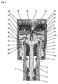
- Fig. 1 represents a device (1) mounted on a normal inflating valve for tires.
- Said valve substantially consists of a metallic tube (2) containing a body (3) fixed to its internal part through a threaded sealed connection (4) where a self-closing closure member (5) with sealing gasket (6), maintained in closing position by means of a spring (7) can axially slide.
- the closure member (5) is capable of automatically opening if the pressure, acting on its part faced toward the external side, that is in the chamber (8), multiplied by the effective surface of the sealing gasket (6), generates an axial downward force higher than the one due to the pressure acting on its part faced toward the internal side, that is in the chamber (9), or inside the tire, multiplied by the effective surface of the sealing gasket (6) together with the additional force of the spring (7) or, vice-versa, of keeping closed if the force due to the pressure in the part faced toward the external side (chamber 8) is lower than the one due to the pressure of the tire (chamber 9) together with the additional force of the spring (7).
- the closure member (5) can be opened also by a mechanical action from the external side applying a force to its end going to the internal side as shown in Fig. 2.
- the device (1) is screwed on the inflating valve instead of the usual protecting cup.
- the device (1) and more of its internal members have an axial-symmetrical form.
- the device (1) comprises a threaded body (11) formed by two parts (11 a and 11b) welded each other: the threaded body (11) engages the threaded end (10) of the inflating valve of the tire.
- An external envelope (12) is connected to the threaded body (11) through anti-unscrewing clicks controlling the most applied torque and generating an axial pushing as known from other documents.
- Said devices realise an unidirectional free tripper allowing the transmission of the torque between the envelope (12) and the threaded body (11) in the screwing direction only.
- a sufficient tightening torque capable of contrasting a unscrewing torque
- the clamping is necessary in order to avoid the unscrewing of the system and its losing during the vehicle moving due to external forces and vibrations and also to assure the efficient of the functions the clamping must do.
- the clamping of the system on the valve is properly effected when it is carried out by a suitable and not excessive final torque.
- a suitable and not excessive final torque Either in case of manual screwing of the system on the end of the inflating valve of the tire, or, above all, in case of use of auxiliary tools for applying a stronger clamping torque, the risk to apply a clamping torque resulting too much strong capable of damaging the system and/or a sealing gasket (23) located between the threaded body (11) and the end (10) of the valve exists.
- the system is, therefore, capable of assuring, also in case of manoeuvring by a not specialised staff and without suitable tools (and therefore not able to verify if the applied screwing torque has a value that is sufficient for the purpose), the efficient and complete clamping of the threaded members (10, 11) and of the gasket (23).
- a spring (24) is located between the threaded body (11) and a centring sleeve (25).
- the spring (24) pushes upwards the sensor/amplifier/transducer/actuator system (26) which, before the screwing and clamping manoeuvring of the system (1) on the valve, is found in unloading position (Fig. 2). Therefore, it rests on the upper wall (27) to the opposite end of the threaded body and rigidly sealing connected to the envelope (12).
- the sealing is due to a gasket (28) located between the end of the envelope (12) and an abutting on the wall (27).
- the pushing carried out by the wall (27) on the system (26) causes the translation of said system towards the upper wall (29) of the threaded body (11) up to limit stop.
- the lower end (30) of the housing (31) of the system (26) meets the upper end of the closure member (5) and pushes said member (5) towards the internal part of the valve (2) against the force of the spring (7) and of the pushing of the pressure due to the gas contained in the tire on the efficient section of the gasket (6).
- the chamber (9), connected to the internal part of the tire, is joined to the chamber (8) delimited by the end (10) of the valve (2), the upper wall (29) of the threaded body (12), the gasket (23) and a gasket (32) capable of sealing the lower end (30) of the housing (31) of the system (26) and the cylindrical hollow (33) obtained on the upper wall (29) of the threaded body (11) (see Fig. 1).
- the gasket (6) is open until the system (26) is found near the threaded body (11), while its automatic closing occurs when the system (26) is far from the threaded body (11).
- Apparatuses capable of obtaining functions of measuring, amplifying and transducing of the signal due to the difference between the pressure of the gas contained inside the tire and the environmental pressure and of signalling of the exceeding the pre-established threshold.
- said apparatuses are capable of obtaining an efficient pre-establishment of the operating threshold and signalling for differences in pressure between 0,05 and 3 MPa with a definition, precision and reproducibility according to the requirements of using of the tires by means of a limited number of components.
- a shaped plate (48) used for rigidly and plane supporting a plurality of Belleville washers (49) is located inside the housing (31); said washers (49) consisting of shaped like a cone and drilled disks as shown in Figures 3, 4.
- the hub (51) being drilled in the middle.
- a guiding plate (52) provides the centring of the movable closure member (50), resting on the housing (31) through the plate (48).
- the diaphragm presents a central hole where the hub (51) is inserted.
- the same diaphragm (53) is then sealed on the guiding plate (52) by a sleeve plate (54) clamped by the riveting (55) of the housing (31).
- the sleeve plate (54) guides the component (39) while this one axially moves together with the movable closure member (50).
- a seat in the housing (31) houses a gasket (56), which is hold in its position by a riveting, shaped like a lip (57).
- the pushing P of Fig. 2 is transmitted by the wall (27) to the component (39), which transmits said pushing P to the movable closure member (50); for this reason the member (50) compresses the Belleville washers (49) until the edge of the central hole touches the plate (48).
- the movable closure member (50) compresses the gasket (56) for the sealing between the member (50) and the housing (31).
- This operation produces an axial drive (58), (59), (60), which, due to the radial passage (73) on the end (30) of the housing (31), connects the chamber (8) to the chamber (36) and disconnects the chamber (36) from a chamber (6.4) delimited by the housing (31), the movable closure member (50)/diaphragm (53)/guiding plate (52) system and by the gasket (56).
- the chamber (64) communicates with the environment through a hole (65) drilled in the housing (31), the chamber (66), the passage (67) to the cavity (22) found on the basis of the threaded body (11) and the envelope (12) connected to the environment through a hole drilled in the basis of the threaded body (11).
- the section (58) of said torque consists of an axial hole (62) found at the end (30) of the housing (31).
- the section (58) of said torque consists of an axial hole drilled in a screw (61) screwed in a hole (62) found at the end (30) of the housing (31).
- the section (59) of said torque consists of a hole (63) located in the housing (31) and in series with respect to the hole (62) where the screw (61) is screwed.
- the section (60) of said torque consists of a hole located inside the hub (51).
- the Belleville washers (49) replace, in this case, the bistable lamina of the device as cited in EP-A 0 893 284.
- the chamber (64) replaces the housing located under the bistable lamina.
- the chamber (36) substitutes the chamber located over the bistable lamina.
- the axial drive (58, 59, 60) replaces the channels between the chamber communicating with the inside of the tire and the chamber located over the bistable lamina when the device is loaded.
- the purpose of the system comprising the Belleville washers (49), the group movable closure member (50)/diaphragm (53)/guiding plate (52) and gasket (56) is to measure the difference in pressure between the chamber (36) and the environment when the device is loaded, to signal when said difference decreases under a pre-established threshold value and then to define the same threshold value.
- the pressure in the chamber (36) acts on the section of the diaphragm (53) on which said pressure operates; said section being delimited by clamping sealing portions with respect to the guiding plate (52) and the movable closure member (50).
- the diaphragm (53) generates a frictionless seal between the movable closure member (50) and the guiding plate (52).
- the force due to the pressure in the chamber (36) acting on the movable closure member (50) is proportional to the surface externally delimited by the dimension of the external contour (68) of the member (50) which mates, with free axial movement, with the centring in the guiding plate (52), and internally delimited by the effective sealing section (on the plane perpendicular to the axis of symmetry of the device) of the gasket (56), since the pressure in the chamber (36) acts in said effective sealing section of the gasket (56), while the external pressure of the chamber (68) operates inside said sealing section.
- planing of the sections regarding to the surface externally delimited by the dimension of the external contour (68) of the movable closure member (50) and to the effective sealing section of the gasket (56) allows to regulate the force of the pressure in the chamber (36) on the movable closure member (50).
- the number and the planing of the Belleville washers (49) and the planing of the gasket (56) define the equilibrium of the movable closure member (50) on which the opposite forces, due to the pressure in the chamber (36) and of the Belleville washers (49) together with the gasket (56), act.
- An annular gasket (35) separates the chamber (36), located between the wall (27) and the system (26), from the chamber (37), found between the centring sleeve (25) and the environment, the chamber (37) communicating with the environment through a hole (not represented) at the basis of the threaded body (11).
- This gasket (35) co-operates with the spring (24) in order to realise the same function of the bellows of EP-A 0 893 284.
- the unscrewing of the system (1) acting on the external envelope (12) is prevented by the free tripper, on condition that the treaded body is clamped by screwing causing a clamping torque the value of which is higher than the torque capable of being transmitted towards the unscrewing, which exists even if rather low.
- an axial hole (69) is provided in the wall (29); said axial hole (69) connecting the downwards portion of the gasket (23), with respect to the chamber (8), with the chamber (64).
- the gas tends to come into the chamber (64) acting on the active section of the diaphragm (53) causing an additional pushing with respect to the pushing of the Belleville washers (49) increasing the acting threshold.
- the signalling of the exceeding of the threshold occurs before the effective pressure in the tire decreases under the predetermined threshold value. So doing it is possible to distinguish the unloading due to the sealing loss of the gasket (23) with respect to the unloading due to a decreasing of the effective pressure in the tire under the predetermined threshold value.
- Fig. 3 showing the unloaded device, discloses a safety system to prevent gas-leak from the tire through the device, in case the system (26), after unloading, cannot go up.
- a cylindrical self-closing closure member (70) located in the hole (63) is pushed by the spring (71) against the gasket (56), to define a sealing when the movable closure member (50) is unloading condition.
- a laminar protuberance (72) extending the hub (51) moves away the cylindrical self-closing closure member (70) from the gasket (56) allowing the connection between the chamber (8) and the chamber (36).
- a further regulation of the acting threshold of the device is reached by a screw (61) screwed in the hole (62) of Fig. 4.
- the pushing of the spring (71) is regulated; said pushing moves the cylindrical self-closing closure member (70) against the gasket (56).
- Said pushing acts on the laminar protuberance (72) of the movable closure member (50) when this one is loaded, in addition to the pushing of the Belleville washers (49).
Landscapes
- Engineering & Computer Science (AREA)
- Mechanical Engineering (AREA)
- Measuring Fluid Pressure (AREA)
- Tires In General (AREA)
Applications Claiming Priority (3)
| Application Number | Priority Date | Filing Date | Title |
|---|---|---|---|
| IT000781A ITBO20020781A1 (it) | 2002-12-12 | 2002-12-12 | Sistema per la predeterminazione della soglia d'intervento |
| ITBO20020781 | 2002-12-12 | ||
| US10/735,472 US7146842B2 (en) | 2002-12-12 | 2003-12-12 | System for predetermining the operating threshold of a device surveying the radial deformation state of a tire |
Publications (1)
| Publication Number | Publication Date |
|---|---|
| EP1526006A1 true EP1526006A1 (de) | 2005-04-27 |
Family
ID=34921526
Family Applications (1)
| Application Number | Title | Priority Date | Filing Date |
|---|---|---|---|
| EP03017029A Withdrawn EP1526006A1 (de) | 2002-12-12 | 2003-07-28 | System für das Festlegen der Ansprechschwelle einer Vorrichtung zur Überwachung des Zustandes der radialen Deformation eines Luftreifens |
Country Status (4)
| Country | Link |
|---|---|
| US (1) | US7146842B2 (de) |
| EP (1) | EP1526006A1 (de) |
| JP (1) | JP2004189224A (de) |
| CA (1) | CA2452989A1 (de) |
Families Citing this family (1)
| Publication number | Priority date | Publication date | Assignee | Title |
|---|---|---|---|---|
| ITBO20030737A1 (it) * | 2003-12-09 | 2005-06-10 | Marcello Pellicciari | Dispositivo per la sorveglianza della pressione dei fluidi |
Citations (4)
| Publication number | Priority date | Publication date | Assignee | Title |
|---|---|---|---|---|
| US4606391A (en) * | 1983-10-28 | 1986-08-19 | Rainer Achterholt | Valve cap with pressure drop indication for pneumatic tires |
| US5569849A (en) * | 1995-08-24 | 1996-10-29 | Cummings; Craig | Visual tire cap pressure gauge |
| WO1997042044A1 (en) * | 1996-05-07 | 1997-11-13 | Innovative Enterprises Limited | Pressure indicating devices |
| EP0893284A1 (de) * | 1998-05-28 | 1999-01-27 | Giovanni Barbanti | Vorrichtung zum Signalisieren des Reifendruckzustandes |
-
2003
- 2003-07-28 EP EP03017029A patent/EP1526006A1/de not_active Withdrawn
- 2003-12-10 CA CA002452989A patent/CA2452989A1/en not_active Abandoned
- 2003-12-11 JP JP2003412938A patent/JP2004189224A/ja active Pending
- 2003-12-12 US US10/735,472 patent/US7146842B2/en not_active Expired - Fee Related
Patent Citations (4)
| Publication number | Priority date | Publication date | Assignee | Title |
|---|---|---|---|---|
| US4606391A (en) * | 1983-10-28 | 1986-08-19 | Rainer Achterholt | Valve cap with pressure drop indication for pneumatic tires |
| US5569849A (en) * | 1995-08-24 | 1996-10-29 | Cummings; Craig | Visual tire cap pressure gauge |
| WO1997042044A1 (en) * | 1996-05-07 | 1997-11-13 | Innovative Enterprises Limited | Pressure indicating devices |
| EP0893284A1 (de) * | 1998-05-28 | 1999-01-27 | Giovanni Barbanti | Vorrichtung zum Signalisieren des Reifendruckzustandes |
Also Published As
| Publication number | Publication date |
|---|---|
| CA2452989A1 (en) | 2004-06-12 |
| US7146842B2 (en) | 2006-12-12 |
| JP2004189224A (ja) | 2004-07-08 |
| US20050166662A1 (en) | 2005-08-04 |
Similar Documents
| Publication | Publication Date | Title |
|---|---|---|
| US6015134A (en) | Pneumatic actuator assembly | |
| US5419361A (en) | Fluid pressure actuated flow control valve | |
| US4246930A (en) | Relief valve | |
| US3036592A (en) | Valve assembly | |
| US4776562A (en) | Dual piston pneumatically operated valve | |
| US4761999A (en) | Set pressure verification device and method | |
| US5822173A (en) | Condition responsive electrical apparatus having improved low cost housing | |
| US4516599A (en) | Valve mechanism for low temperature applications | |
| US7146842B2 (en) | System for predetermining the operating threshold of a device surveying the radial deformation state of a tire | |
| US3577696A (en) | Method of filling a pressure vessel assembly | |
| US6053192A (en) | Low operating force pressure regulator | |
| WO1980000482A1 (en) | Valve | |
| US6564827B1 (en) | Shut-off device for the filling device of a pressure tank | |
| EP1428692B1 (de) | Vorrichtung zur Überwachung des Zustandes der radialen Deformation eines Luftreifens | |
| US7343871B2 (en) | Device for surveying the pressure of fluids housed in tanks or flowing through ducts | |
| US4893782A (en) | Metallic seat for fluid valve | |
| US4480663A (en) | Pneumatic relay valve | |
| US4671319A (en) | Autonomous assistance device for a safety valve | |
| JPH0142862B2 (de) | ||
| US3930521A (en) | Gas charging valve for accumulator | |
| US2689581A (en) | High-pressure safety relief valve | |
| US4601254A (en) | Tire pressure warning device | |
| EP0001188B1 (de) | Druckempfindliche Anordnung und Überwachungseinrichtung welche diese Anordnung enthält | |
| CN218494291U (zh) | 气体调压阀控制机构 | |
| KR20040051531A (ko) | 타이어의 반경방향 변형 상태를 검사하는 장치의 작동임계치를 미리 결정하기 위한 시스템 |
Legal Events
| Date | Code | Title | Description |
|---|---|---|---|
| PUAI | Public reference made under article 153(3) epc to a published international application that has entered the european phase |
Free format text: ORIGINAL CODE: 0009012 |
|
| AK | Designated contracting states |
Kind code of ref document: A1 Designated state(s): AT BE BG CH CY CZ DE DK EE ES FI FR GB GR HU IE IT LI LU MC NL PT RO SE SI SK TR |
|
| AX | Request for extension of the european patent |
Extension state: AL LT LV MK |
|
| 17P | Request for examination filed |
Effective date: 20041208 |
|
| AKX | Designation fees paid |
Designated state(s): AT BE BG CH CY CZ DE DK EE ES FI FR GB GR HU IE IT LI LU MC NL PT RO SE SI SK TR |
|
| APBN | Date of receipt of notice of appeal recorded |
Free format text: ORIGINAL CODE: EPIDOSNNOA2E |
|
| APBR | Date of receipt of statement of grounds of appeal recorded |
Free format text: ORIGINAL CODE: EPIDOSNNOA3E |
|
| APAF | Appeal reference modified |
Free format text: ORIGINAL CODE: EPIDOSCREFNE |
|
| APAF | Appeal reference modified |
Free format text: ORIGINAL CODE: EPIDOSCREFNE |
|
| APAK | Date of receipt of statement of grounds of an appeal modified |
Free format text: ORIGINAL CODE: EPIDOSCNOA3E |
|
| APAX | Date of receipt of notice of appeal deleted |
Free format text: ORIGINAL CODE: EPIDOSDNOA2E |
|
| APAZ | Date of receipt of statement of grounds of appeal deleted |
Free format text: ORIGINAL CODE: EPIDOSDNOA3E |
|
| APBK | Appeal reference recorded |
Free format text: ORIGINAL CODE: EPIDOSNREFNE |
|
| APBN | Date of receipt of notice of appeal recorded |
Free format text: ORIGINAL CODE: EPIDOSNNOA2E |
|
| APBR | Date of receipt of statement of grounds of appeal recorded |
Free format text: ORIGINAL CODE: EPIDOSNNOA3E |
|
| APBT | Appeal procedure closed |
Free format text: ORIGINAL CODE: EPIDOSNNOA9E |
|
| STAA | Information on the status of an ep patent application or granted ep patent |
Free format text: STATUS: THE APPLICATION IS DEEMED TO BE WITHDRAWN |
|
| 18D | Application deemed to be withdrawn |
Effective date: 20120201 |