EP1526023A2 - Steuervorrichtung für Hybridfahrzeug - Google Patents
Steuervorrichtung für Hybridfahrzeug Download PDFInfo
- Publication number
- EP1526023A2 EP1526023A2 EP04256438A EP04256438A EP1526023A2 EP 1526023 A2 EP1526023 A2 EP 1526023A2 EP 04256438 A EP04256438 A EP 04256438A EP 04256438 A EP04256438 A EP 04256438A EP 1526023 A2 EP1526023 A2 EP 1526023A2
- Authority
- EP
- European Patent Office
- Prior art keywords
- engine
- coupling
- motor
- torque
- revolution speed
- Prior art date
- Legal status (The legal status is an assumption and is not a legal conclusion. Google has not performed a legal analysis and makes no representation as to the accuracy of the status listed.)
- Withdrawn
Links
Images


Classifications
-
- B—PERFORMING OPERATIONS; TRANSPORTING
- B60—VEHICLES IN GENERAL
- B60W—CONJOINT CONTROL OF VEHICLE SUB-UNITS OF DIFFERENT TYPE OR DIFFERENT FUNCTION; CONTROL SYSTEMS SPECIALLY ADAPTED FOR HYBRID VEHICLES; ROAD VEHICLE DRIVE CONTROL SYSTEMS FOR PURPOSES NOT RELATED TO THE CONTROL OF A PARTICULAR SUB-UNIT
- B60W20/00—Control systems specially adapted for hybrid vehicles
- B60W20/10—Controlling the power contribution of each of the prime movers to meet required power demand
-
- B—PERFORMING OPERATIONS; TRANSPORTING
- B60—VEHICLES IN GENERAL
- B60K—ARRANGEMENT OR MOUNTING OF PROPULSION UNITS OR OF TRANSMISSIONS IN VEHICLES; ARRANGEMENT OR MOUNTING OF PLURAL DIVERSE PRIME-MOVERS IN VEHICLES; AUXILIARY DRIVES FOR VEHICLES; INSTRUMENTATION OR DASHBOARDS FOR VEHICLES; ARRANGEMENTS IN CONNECTION WITH COOLING, AIR INTAKE, GAS EXHAUST OR FUEL SUPPLY OF PROPULSION UNITS IN VEHICLES
- B60K6/00—Arrangement or mounting of plural diverse prime-movers for mutual or common propulsion, e.g. hybrid propulsion systems comprising electric motors and internal combustion engines
- B60K6/20—Arrangement or mounting of plural diverse prime-movers for mutual or common propulsion, e.g. hybrid propulsion systems comprising electric motors and internal combustion engines the prime-movers consisting of electric motors and internal combustion engines, e.g. HEVs
- B60K6/22—Arrangement or mounting of plural diverse prime-movers for mutual or common propulsion, e.g. hybrid propulsion systems comprising electric motors and internal combustion engines the prime-movers consisting of electric motors and internal combustion engines, e.g. HEVs characterised by apparatus, components or means specially adapted for HEVs
- B60K6/38—Arrangement or mounting of plural diverse prime-movers for mutual or common propulsion, e.g. hybrid propulsion systems comprising electric motors and internal combustion engines the prime-movers consisting of electric motors and internal combustion engines, e.g. HEVs characterised by apparatus, components or means specially adapted for HEVs characterised by the driveline clutches
- B60K6/387—Actuated clutches, i.e. clutches engaged or disengaged by electric, hydraulic or mechanical actuating means
-
- B—PERFORMING OPERATIONS; TRANSPORTING
- B60—VEHICLES IN GENERAL
- B60K—ARRANGEMENT OR MOUNTING OF PROPULSION UNITS OR OF TRANSMISSIONS IN VEHICLES; ARRANGEMENT OR MOUNTING OF PLURAL DIVERSE PRIME-MOVERS IN VEHICLES; AUXILIARY DRIVES FOR VEHICLES; INSTRUMENTATION OR DASHBOARDS FOR VEHICLES; ARRANGEMENTS IN CONNECTION WITH COOLING, AIR INTAKE, GAS EXHAUST OR FUEL SUPPLY OF PROPULSION UNITS IN VEHICLES
- B60K6/00—Arrangement or mounting of plural diverse prime-movers for mutual or common propulsion, e.g. hybrid propulsion systems comprising electric motors and internal combustion engines
- B60K6/20—Arrangement or mounting of plural diverse prime-movers for mutual or common propulsion, e.g. hybrid propulsion systems comprising electric motors and internal combustion engines the prime-movers consisting of electric motors and internal combustion engines, e.g. HEVs
- B60K6/42—Arrangement or mounting of plural diverse prime-movers for mutual or common propulsion, e.g. hybrid propulsion systems comprising electric motors and internal combustion engines the prime-movers consisting of electric motors and internal combustion engines, e.g. HEVs characterised by the architecture of the hybrid electric vehicle
- B60K6/44—Series-parallel type
- B60K6/442—Series-parallel switching type
-
- B—PERFORMING OPERATIONS; TRANSPORTING
- B60—VEHICLES IN GENERAL
- B60K—ARRANGEMENT OR MOUNTING OF PROPULSION UNITS OR OF TRANSMISSIONS IN VEHICLES; ARRANGEMENT OR MOUNTING OF PLURAL DIVERSE PRIME-MOVERS IN VEHICLES; AUXILIARY DRIVES FOR VEHICLES; INSTRUMENTATION OR DASHBOARDS FOR VEHICLES; ARRANGEMENTS IN CONNECTION WITH COOLING, AIR INTAKE, GAS EXHAUST OR FUEL SUPPLY OF PROPULSION UNITS IN VEHICLES
- B60K6/00—Arrangement or mounting of plural diverse prime-movers for mutual or common propulsion, e.g. hybrid propulsion systems comprising electric motors and internal combustion engines
- B60K6/20—Arrangement or mounting of plural diverse prime-movers for mutual or common propulsion, e.g. hybrid propulsion systems comprising electric motors and internal combustion engines the prime-movers consisting of electric motors and internal combustion engines, e.g. HEVs
- B60K6/42—Arrangement or mounting of plural diverse prime-movers for mutual or common propulsion, e.g. hybrid propulsion systems comprising electric motors and internal combustion engines the prime-movers consisting of electric motors and internal combustion engines, e.g. HEVs characterised by the architecture of the hybrid electric vehicle
- B60K6/48—Parallel type
- B60K6/485—Motor-assist type
-
- B—PERFORMING OPERATIONS; TRANSPORTING
- B60—VEHICLES IN GENERAL
- B60W—CONJOINT CONTROL OF VEHICLE SUB-UNITS OF DIFFERENT TYPE OR DIFFERENT FUNCTION; CONTROL SYSTEMS SPECIALLY ADAPTED FOR HYBRID VEHICLES; ROAD VEHICLE DRIVE CONTROL SYSTEMS FOR PURPOSES NOT RELATED TO THE CONTROL OF A PARTICULAR SUB-UNIT
- B60W10/00—Conjoint control of vehicle sub-units of different type or different function
- B60W10/02—Conjoint control of vehicle sub-units of different type or different function including control of driveline clutches
-
- B—PERFORMING OPERATIONS; TRANSPORTING
- B60—VEHICLES IN GENERAL
- B60W—CONJOINT CONTROL OF VEHICLE SUB-UNITS OF DIFFERENT TYPE OR DIFFERENT FUNCTION; CONTROL SYSTEMS SPECIALLY ADAPTED FOR HYBRID VEHICLES; ROAD VEHICLE DRIVE CONTROL SYSTEMS FOR PURPOSES NOT RELATED TO THE CONTROL OF A PARTICULAR SUB-UNIT
- B60W10/00—Conjoint control of vehicle sub-units of different type or different function
- B60W10/04—Conjoint control of vehicle sub-units of different type or different function including control of propulsion units
- B60W10/06—Conjoint control of vehicle sub-units of different type or different function including control of propulsion units including control of combustion engines
-
- B—PERFORMING OPERATIONS; TRANSPORTING
- B60—VEHICLES IN GENERAL
- B60W—CONJOINT CONTROL OF VEHICLE SUB-UNITS OF DIFFERENT TYPE OR DIFFERENT FUNCTION; CONTROL SYSTEMS SPECIALLY ADAPTED FOR HYBRID VEHICLES; ROAD VEHICLE DRIVE CONTROL SYSTEMS FOR PURPOSES NOT RELATED TO THE CONTROL OF A PARTICULAR SUB-UNIT
- B60W10/00—Conjoint control of vehicle sub-units of different type or different function
- B60W10/04—Conjoint control of vehicle sub-units of different type or different function including control of propulsion units
- B60W10/08—Conjoint control of vehicle sub-units of different type or different function including control of propulsion units including control of electric propulsion units, e.g. motors or generators
-
- B—PERFORMING OPERATIONS; TRANSPORTING
- B60—VEHICLES IN GENERAL
- B60W—CONJOINT CONTROL OF VEHICLE SUB-UNITS OF DIFFERENT TYPE OR DIFFERENT FUNCTION; CONTROL SYSTEMS SPECIALLY ADAPTED FOR HYBRID VEHICLES; ROAD VEHICLE DRIVE CONTROL SYSTEMS FOR PURPOSES NOT RELATED TO THE CONTROL OF A PARTICULAR SUB-UNIT
- B60W20/00—Control systems specially adapted for hybrid vehicles
-
- B—PERFORMING OPERATIONS; TRANSPORTING
- B60—VEHICLES IN GENERAL
- B60K—ARRANGEMENT OR MOUNTING OF PROPULSION UNITS OR OF TRANSMISSIONS IN VEHICLES; ARRANGEMENT OR MOUNTING OF PLURAL DIVERSE PRIME-MOVERS IN VEHICLES; AUXILIARY DRIVES FOR VEHICLES; INSTRUMENTATION OR DASHBOARDS FOR VEHICLES; ARRANGEMENTS IN CONNECTION WITH COOLING, AIR INTAKE, GAS EXHAUST OR FUEL SUPPLY OF PROPULSION UNITS IN VEHICLES
- B60K1/00—Arrangement or mounting of electrical propulsion units
- B60K1/02—Arrangement or mounting of electrical propulsion units comprising more than one electric motor
-
- B—PERFORMING OPERATIONS; TRANSPORTING
- B60—VEHICLES IN GENERAL
- B60K—ARRANGEMENT OR MOUNTING OF PROPULSION UNITS OR OF TRANSMISSIONS IN VEHICLES; ARRANGEMENT OR MOUNTING OF PLURAL DIVERSE PRIME-MOVERS IN VEHICLES; AUXILIARY DRIVES FOR VEHICLES; INSTRUMENTATION OR DASHBOARDS FOR VEHICLES; ARRANGEMENTS IN CONNECTION WITH COOLING, AIR INTAKE, GAS EXHAUST OR FUEL SUPPLY OF PROPULSION UNITS IN VEHICLES
- B60K6/00—Arrangement or mounting of plural diverse prime-movers for mutual or common propulsion, e.g. hybrid propulsion systems comprising electric motors and internal combustion engines
- B60K6/20—Arrangement or mounting of plural diverse prime-movers for mutual or common propulsion, e.g. hybrid propulsion systems comprising electric motors and internal combustion engines the prime-movers consisting of electric motors and internal combustion engines, e.g. HEVs
- B60K6/22—Arrangement or mounting of plural diverse prime-movers for mutual or common propulsion, e.g. hybrid propulsion systems comprising electric motors and internal combustion engines the prime-movers consisting of electric motors and internal combustion engines, e.g. HEVs characterised by apparatus, components or means specially adapted for HEVs
- B60K6/26—Arrangement or mounting of plural diverse prime-movers for mutual or common propulsion, e.g. hybrid propulsion systems comprising electric motors and internal combustion engines the prime-movers consisting of electric motors and internal combustion engines, e.g. HEVs characterised by apparatus, components or means specially adapted for HEVs characterised by the motors or the generators
- B60K2006/268—Electric drive motor starts the engine, i.e. used as starter motor
-
- B—PERFORMING OPERATIONS; TRANSPORTING
- B60—VEHICLES IN GENERAL
- B60L—PROPULSION OF ELECTRICALLY-PROPELLED VEHICLES; SUPPLYING ELECTRIC POWER FOR AUXILIARY EQUIPMENT OF ELECTRICALLY-PROPELLED VEHICLES; ELECTRODYNAMIC BRAKE SYSTEMS FOR VEHICLES IN GENERAL; MAGNETIC SUSPENSION OR LEVITATION FOR VEHICLES; MONITORING OPERATING VARIABLES OF ELECTRICALLY-PROPELLED VEHICLES; ELECTRIC SAFETY DEVICES FOR ELECTRICALLY-PROPELLED VEHICLES
- B60L2240/00—Control parameters of input or output; Target parameters
- B60L2240/40—Drive Train control parameters
- B60L2240/42—Drive Train control parameters related to electric machines
- B60L2240/421—Speed
-
- B—PERFORMING OPERATIONS; TRANSPORTING
- B60—VEHICLES IN GENERAL
- B60L—PROPULSION OF ELECTRICALLY-PROPELLED VEHICLES; SUPPLYING ELECTRIC POWER FOR AUXILIARY EQUIPMENT OF ELECTRICALLY-PROPELLED VEHICLES; ELECTRODYNAMIC BRAKE SYSTEMS FOR VEHICLES IN GENERAL; MAGNETIC SUSPENSION OR LEVITATION FOR VEHICLES; MONITORING OPERATING VARIABLES OF ELECTRICALLY-PROPELLED VEHICLES; ELECTRIC SAFETY DEVICES FOR ELECTRICALLY-PROPELLED VEHICLES
- B60L2240/00—Control parameters of input or output; Target parameters
- B60L2240/40—Drive Train control parameters
- B60L2240/42—Drive Train control parameters related to electric machines
- B60L2240/423—Torque
-
- B—PERFORMING OPERATIONS; TRANSPORTING
- B60—VEHICLES IN GENERAL
- B60L—PROPULSION OF ELECTRICALLY-PROPELLED VEHICLES; SUPPLYING ELECTRIC POWER FOR AUXILIARY EQUIPMENT OF ELECTRICALLY-PROPELLED VEHICLES; ELECTRODYNAMIC BRAKE SYSTEMS FOR VEHICLES IN GENERAL; MAGNETIC SUSPENSION OR LEVITATION FOR VEHICLES; MONITORING OPERATING VARIABLES OF ELECTRICALLY-PROPELLED VEHICLES; ELECTRIC SAFETY DEVICES FOR ELECTRICALLY-PROPELLED VEHICLES
- B60L2240/00—Control parameters of input or output; Target parameters
- B60L2240/40—Drive Train control parameters
- B60L2240/44—Drive Train control parameters related to combustion engines
- B60L2240/441—Speed
-
- B—PERFORMING OPERATIONS; TRANSPORTING
- B60—VEHICLES IN GENERAL
- B60W—CONJOINT CONTROL OF VEHICLE SUB-UNITS OF DIFFERENT TYPE OR DIFFERENT FUNCTION; CONTROL SYSTEMS SPECIALLY ADAPTED FOR HYBRID VEHICLES; ROAD VEHICLE DRIVE CONTROL SYSTEMS FOR PURPOSES NOT RELATED TO THE CONTROL OF A PARTICULAR SUB-UNIT
- B60W2510/00—Input parameters relating to a particular sub-units
- B60W2510/06—Combustion engines, Gas turbines
- B60W2510/0638—Engine speed
-
- B—PERFORMING OPERATIONS; TRANSPORTING
- B60—VEHICLES IN GENERAL
- B60W—CONJOINT CONTROL OF VEHICLE SUB-UNITS OF DIFFERENT TYPE OR DIFFERENT FUNCTION; CONTROL SYSTEMS SPECIALLY ADAPTED FOR HYBRID VEHICLES; ROAD VEHICLE DRIVE CONTROL SYSTEMS FOR PURPOSES NOT RELATED TO THE CONTROL OF A PARTICULAR SUB-UNIT
- B60W2710/00—Output or target parameters relating to a particular sub-units
- B60W2710/06—Combustion engines, Gas turbines
- B60W2710/0666—Engine torque
-
- B—PERFORMING OPERATIONS; TRANSPORTING
- B60—VEHICLES IN GENERAL
- B60W—CONJOINT CONTROL OF VEHICLE SUB-UNITS OF DIFFERENT TYPE OR DIFFERENT FUNCTION; CONTROL SYSTEMS SPECIALLY ADAPTED FOR HYBRID VEHICLES; ROAD VEHICLE DRIVE CONTROL SYSTEMS FOR PURPOSES NOT RELATED TO THE CONTROL OF A PARTICULAR SUB-UNIT
- B60W2710/00—Output or target parameters relating to a particular sub-units
- B60W2710/08—Electric propulsion units
- B60W2710/081—Speed
-
- B—PERFORMING OPERATIONS; TRANSPORTING
- B60—VEHICLES IN GENERAL
- B60W—CONJOINT CONTROL OF VEHICLE SUB-UNITS OF DIFFERENT TYPE OR DIFFERENT FUNCTION; CONTROL SYSTEMS SPECIALLY ADAPTED FOR HYBRID VEHICLES; ROAD VEHICLE DRIVE CONTROL SYSTEMS FOR PURPOSES NOT RELATED TO THE CONTROL OF A PARTICULAR SUB-UNIT
- B60W2710/00—Output or target parameters relating to a particular sub-units
- B60W2710/08—Electric propulsion units
- B60W2710/083—Torque
-
- Y—GENERAL TAGGING OF NEW TECHNOLOGICAL DEVELOPMENTS; GENERAL TAGGING OF CROSS-SECTIONAL TECHNOLOGIES SPANNING OVER SEVERAL SECTIONS OF THE IPC; TECHNICAL SUBJECTS COVERED BY FORMER USPC CROSS-REFERENCE ART COLLECTIONS [XRACs] AND DIGESTS
- Y02—TECHNOLOGIES OR APPLICATIONS FOR MITIGATION OR ADAPTATION AGAINST CLIMATE CHANGE
- Y02T—CLIMATE CHANGE MITIGATION TECHNOLOGIES RELATED TO TRANSPORTATION
- Y02T10/00—Road transport of goods or passengers
- Y02T10/60—Other road transportation technologies with climate change mitigation effect
- Y02T10/62—Hybrid vehicles
-
- Y—GENERAL TAGGING OF NEW TECHNOLOGICAL DEVELOPMENTS; GENERAL TAGGING OF CROSS-SECTIONAL TECHNOLOGIES SPANNING OVER SEVERAL SECTIONS OF THE IPC; TECHNICAL SUBJECTS COVERED BY FORMER USPC CROSS-REFERENCE ART COLLECTIONS [XRACs] AND DIGESTS
- Y02—TECHNOLOGIES OR APPLICATIONS FOR MITIGATION OR ADAPTATION AGAINST CLIMATE CHANGE
- Y02T—CLIMATE CHANGE MITIGATION TECHNOLOGIES RELATED TO TRANSPORTATION
- Y02T10/00—Road transport of goods or passengers
- Y02T10/60—Other road transportation technologies with climate change mitigation effect
- Y02T10/64—Electric machine technologies in electromobility
Definitions
- the present invention relates to a control device for a hybrid vehicle that uses an engine and a drive motor together as a source of power.
- a hybrid vehicle which uses an internal combustion engine such as a gasoline engine and an electric motor together as a source of power of the vehicle, includes a series and parallel type.
- This type of hybrid vehicle is provided with a power generator in addition to the engine and the drive motor, and driving of the vehicle is shifted to any one of driving by the engine, driving by the drive motor, and driving by both of the engine and the motor depending on a running state, whereby the power generator can be driven by the engine at a time of running by the drive motor.
- the hybrid vehicle can be changed to a motor drive mode of driving the vehicle only by the drive motor, and an engine drive mode of driving the vehicle by the engine or by the drive motor as well as the engine.
- the vehicle can be driven by the drive motor at a starting time when driving torque is required, and the vehicle can be driven by the engine when the vehicle speed is increased, and the vehicle can be driven by the drive motor and the engine at a high-load running time such as an uphill running time (see Japanese Patent Laid-open No. 2000-289472).
- the running in which the vehicle is driven by both of the engine and the drive motor under the engine drive mode is also called a parallel running type.
- This type of hybrid vehicle is shifted in many cases from the running only by the motor to the running by both of the motor and the engine, and the motor driving is performed until a remaining capacity (SOC) of a battery becomes small.
- SOC remaining capacity
- the vehicle is motor-driven when high torque and a low speed are required at, for example, a starting time or the like.
- normal running for example, if the vehicle has a speed of 30 km/h or more, it is shifted to the parallel running by both of the engine and the motor. Since an engine speed is largely changed depending on a load and a vehicle speed etc. under the parallel running, it is desirable to make an operation range in which the parallel running is performed as small as possible, in order to operate the engine in an efficient range as long as possible.
- This type of hybrid vehicle has a motor-power transmission path for transmitting motor torque to drive wheels, and an engine-power transmission path for transmitting engine torque to the drive wheels.
- the engine-power transmission path is provided with a clutch, i.e., an engagement apparatus for changing the path to a power-transmission state and a cut-off state. Therefore, when the running is shifted from the motor drive mode to the engine drive mode, the engine torque is transmitted to the drive wheels by connecting a clutch.
- a clutch disc is engaged while slipping, so that it is possible to reduce a change shock caused by such a change.
- a hydraulic pump since it is necessary to perform engaging and disengaging operations of the multiple wet clutch by a hydraulic plunger, a hydraulic pump requires being mounted on the vehicle. However, in the hybrid vehicle, it is preferable that the hydraulic pump is not mounted. If a mechanical clutch, i.e., a coupling that works based on an electric signal is used to connect and disconnect it and the engine-power transmission path, the change shock is increased, so that there is the problem that a smooth change can not be performed.
- An object of the present invention is to prevent occurrence of a change shock caused in shifting the vehicle from a motor driving state to an engine driving state.
- Another object of the present invention is to prevent a change shock caused in shifting the vehicle from an engine driving state to a motor driving state.
- a control device for a hybrid vehicle which comprises: an engine driving drive wheels via an engine-power transmission path; a drive motor driving said drive wheels via a motor-power transmission path; a power generating motor provided to said engine-power transmission path, starting said engine, and generating power by said engine; and a coupling provided to said engine-power transmission path and shifted to a connection state of transmitting engine power to said drive wheels and a disconnection state of cutting off the transmission, wherein a revolution speed of said power generating motor is controlled based on a revolution speed of said drive motor when said coupling is connected to transmit torque of said engine to said drive wheels under a.state in which the power is transmitted to said drive wheels from said drive motor, said coupling is connected after a revolution speed of an input-side shaft of said coupling and a revolution speed of an output-side shaft thereof are synchronized, and said drive motor and the torque of said engine are controlled in accordance with required torque of the vehicle after said coupling is connected.
- control device further comprises: in connecting said coupling, a synchronization phase for synchronizing the revolution speed of said input-side shaft with the revolution speed of said output-side shaft; a synchronization determining phase for determining whether the synchronization is established; a connection phase for executing a connecting operation of said coupling; and a connection-side-torque cooperation phase for changing engine torque and motor torque after the connection is completed, wherein each of said phases is transited in accordance with an elapsed time or the revolution speed of the power generating motor.
- a target revolution speed of said power generating motor is controlled by a function of time based on a revolution speed at a time of starting the control.
- control device at a time of connecting said coupling, completion of the connection is determined when a state in which an error between the revolution speed and a target revolution speed of said power generating motor is within a predetermined range continues for a predetermined time.
- control device after said coupling is connected, engine torque is increased and motor torque is decreased.
- said power generating motor is controlled in revolution speed until the connection of said coupling is completed, and said power generating motor is controlled in zero torque after the connection is completed.
- a control device for a hybrid vehicle which comprises: an engine driving drive wheels via an engine-power transmission path; a drive motor driving said drive wheels via a motor-power transmission path; a power generating motor provided to said engine-power transmission path, starting said engine, and generating power by said engine; and a coupling provided to said engine-power transmission path and shifted to a connection state of transmitting engine power to said drive wheels and a disconnection state of cutting off the transmission, wherein, in disconnecting said coupling under a state in which the power is transmitted to said drive wheels from said engine and cutting off transmission of said engine torque to said drive wheels, torque of said drive motor and said engine is controlled in accordance with required torque of the vehicle and thereafter said coupling is disconnected, and after the disconnection of said coupling is completed, a revolution speed of said power generating motor is controlled in accordance with a revolution speed of said drive motor so that said input-side shaft and said output-side shaft differ from each other in a revolution speed.
- One embodiment of the control device further comprises: in disconnecting said coupling, a disconnection-side-torque cooperation phase for reducing the engine torque; a disconnection phase for disconnecting said coupling; and a synchronization finishing phase for making said input-side shaft and said output-side shaft differ from each other in a revolution speed, wherein, each of said phases is transited in accordance with an elapsed time or the revolution speed of said power generating motor.
- the revolution speed of said power generating motor after disconnecting said coupling is controlled by a target revolution speed at a time of finishing the synchronization and a function of time.
- control device for a hybrid vehicle at a time of disconnecting said coupling, the engine torque is decreased and motor torque is increased.
- said power generating motor is controlled in zero torque until a disconnecting operation of said coupling is started, and said power generating motor is controlled in revolution speed after the disconnection is started.
- the present invention when a shift between the motor drive mode in which the vehicle is driven by the drive motor and the engine drive mode in which the vehicle is driven by the engine is executed, no gap between drive forces in the respective modes occurs and therefore it is possible to be continuously and smoothly shifted without generating any change shock. Since difference between the revolution speeds is reduced when the shift is made between both modes, it is possible to smoothly shift the modes without generating any change shock. Concurrently, a mechanical coupling, for example, a two-way clutch or the like can be used as the coupling. Accordingly, it is possible to make the structure of the hybrid vehicle simple and compact.
- the coupling can be connected irrespective of a load change of the drive motor and the power generating motor, an impact applied to the coupling becomes always small and a durability of the coupling is improved. Since the coupling can be connected irrespective of a power generation state by the power generating motor, it is possible to charge the battery even while the revolution speed is synchronized. It is possible to elongate a time for synchronizing the revolution speed. Therefore, if the vehicle speed is rapidly changed during the rotation synchronization, working frequency of the connection and disconnection of the coupling is reduced by stopping a mutual transition between the motor drive and the engine drive before the coupling is engaged. Accordingly, it is possible to improve a durability of the coupling.
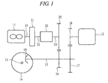
- FIG. 1 is a schematic view showing a power transmission system for a hybrid vehicle.
- the power transmission system has an engine 11 and a drive motor 12 as a source of power for a vehicle, and is used in a front-wheel drive vehicle.
- An axle 13 connected to front wheels serving as drive wheels is attached to a differential gear mechanism (not shown), and a final reduction small gear 16 provided on a front-wheel drive shaft 15 is engaged with a final reduction large gear 14 provided in the differential gear mechanism.
- a drive gear 18 mounted on a main shaft of the drive motor 12 is engaged with a driven gear 17 for speed reduction, which is provided on the front-wheel drive shaft 15, and a motor-power transmission path is formed from the main shaft of the drive motor 12 to the front-wheel drive shaft 15.
- a power generating motor 21 is mounted on a crank shaft 19 of the engine 11, and the power generating motor 21 has a rotor fixed to the crank shaft 19.
- a drive gear 25 engaged with a speed-reducing driven gear 24 provided on the front-wheel drive shaft 15 is provided on an engine-power transmission shaft 23 which is concentric with a rotor output shaft 22 connected to the rotor, and the engine-power transmission path is formed from the crank shaft 19 to the front-wheel drive shaft 15.
- a coupling 26 for shifting engine power to a connection state in which the engine power is transmitted to the drive wheels and to a disconnection state in which the transmission is cut off is provided between the rotor output shaft 22 and the engine-power transmission shaft 23.
- a two-way clutch corresponding to a mechanical clutch is used as the coupling 26, and the rotor output shaft 22 and the engine-power transmission shaft 23 are changed to the connection state and the disconnection state by an electromagnet.
- the power generating motor 21 has a function serving as a starter motor in addition to a function of charging electric power to a battery by being driven by the engine, and the crank shaft 19 is rotated by the power generating motor 21 at a time of starting the engine. Further, since the function serving as a power generator is applied to the drive motor 12, the drive motor 12 can generate power by a regenerative energy at a time of braking and charge the battery with the electric power. Note that the power transmission system shown in FIG. 1 is employed in the front-wheel drive vehicle, but if the power transmission system is applied to a four-wheel drive vehicle in which rear wheels are set also as drive wheels, the main shaft of the drive motor 12 or the front-wheel drive shaft 15 requires being linked to a rear-wheel drive shaft via a power distribution apparatus. Further, the engine-power transmission path is provided only with a gear train constituted by the drive gear 25 and the driven gear 24, but the transmission may be provided to the engine power transmission path by arranging plural stages of transmission gear trains in the engine-power transmission path.
- the hybrid vehicle on which the above-mentioned power transmission system is mounted, has the power generating motor 21 in addition to the engine 11 and the drive motor 12, whereby the driving of the vehicle is shifted to the driving by any one of the engine 11, the drive motor 12, and both in accordance with a running state.
- the vehicle can be driven by use of the drive motor 12 at a starting time when the drive torque is required, and the vehicle can be driven by the engine 11 if the vehicle speed is increased, and the vehicle can be driven by the drive motor 12 and the engine 11 at a high-load running time such as a uphill running time.
- a running mode of the vehicle having such a power transmission system includes a motor drive mode in which only the drive motor 12 is set to a drive source, and an engine drive mode in which the engine 11 is set to a drive source. Even when both of the engine 11 and the drive motor 12 are set to the drive source, the running mode of the vehicle is the engine drive mode. Therefore, since the power of both is transmitted, this mode may be called also a parallel running mode.
- FIGs. 2A and 2B are sectional views showing an example of the coupling 26.
- the coupling 26 has an outer ring 31 formed by a case body spline-connected to the rotor output shaft 22 serving as an input-side shaft, and an inner ring 32 disposed in a cylinder portion of the outer ring 31 and spline-connected to the engine-power transmission shaft 23 serving as an output-side shaft.
- a cylindrical cage 33 is assembled in the outer ring 31 so as to cover the inner ring 32, and a plurality of rollers 34 are arranged on the cage 33.
- An inner peripheral surface of the cylinder portion in the outer ring 31 is formed into a cylindrical shape while an outer peripheral surface of the inner ring 32 is formed into a polygonal shape and a plurality of cam surfaces are formed on the outer peripheral surface.
- An interval between the inner peripheral surface of the outer ring 31 and the outer peripheral surface of the inner ring 32 is changed depending on positions located in a circumferential direction, and the largest interval is set to be larger than an outer diameter of the roller 34.
- a friction flange 35 is fixed to the outer ring 31, and an armature 36 is fixed to the cage 33 so as to oppose to the friction flange 35.
- An electromagnetic coil 37 is fixed to a gear case (not shown) on a vehicle-body side so as to oppose to the friction flange 35.
- a switch spring 38 which applies a spring force to the cage 33 in a direction of disposing each of the rollers 34 at a center portion and in a circumferential direction of each flat surface of the inner ring 32, is provided between the inner ring 32 and the cage 33. For this reason, when a current does not flow in the electromagnetic coil 37, as shown in FIG. 2B, the rollers 34 are disposed at the center portion and in the circumferential direction by the switch spring 38 and are held in such a positional relation as not to simultaneously contact with both of the inner ring 32 and the inner peripheral surface of the outer ring 31. Accordingly, when no current flows in the electromagnetic coil 37, the outer ring 31 becomes rotatable in forward and backward directions with respect to the inner ring 32 without being connected to the inner ring 32 via the rollers 34.
- the armature 36 is drawn to the friction flange 35, so that the outer ring 31 and the cage 33 are integrally rotated.
- the roller 34 is connected between the outer peripheral surface of the inner ring 32, i.e., a cam surface and the inner peripheral surface of the outer ring 31, so that the outer ring 31 can be integrally rotated in both the forward and backward directions together with the inner ring 32. Accordingly, if the current flows in the electromagnetic coil 37, the outer ring is shifted to the connection state in which the power can be transmitted. In contrast, if no current flows in the electromagnetic coil 37, the outer ring is shifted to the disconnection state in which the power transmission is cut off.
- FIG. 3 is a block diagram showing a control circuit of the hybrid vehicle having the power transmission system shown in FIG. 1.
- Detection signals are inputted to a control unit 41 from a power-generating-motor revolution sensor 42 for detecting a revolution speed of the power generating motor 21, a drive-motor revolution sensor 43 for detecting a revolution speed of the drive motor 12, an accelerator opening degree sensor 44 for detecting a pedaling amount of an accelerator pedal by a driver, and the other sensors.
- Control signals are sent to the engine 11, the drive motor 12, the power generating motor 21, and the electromagnetic coil 37 of the coupling 26 from the control unit 41.
- the control unit 41 is provided with a microprocessor arithmetically operating the control signal, a ROM storing a control program, an arithmetic expression, and map data, etc., a RAM temporarily storing data, and the like.
- FIG. 4 is a time chart showing operational control states of the coupling 26 by a connection request signal Fd of the coupling 26 arithmetically operated by the control unit 41 in accordance with a running state of the vehicle and a clutch control signal Fc arithmetically operated based thereon.
- the running state of the vehicle in accordance with the running state of the vehicle, if it is determined that the running state of the motor drive mode should be shifted to the engine drive mode, the running state is shifted to an engine direct-coupled phase E via each of control stages or control steps, that is, each of phases A to D.
- the running state of the engine direct-coupled phase E should be shifted to the motor drive mode
- the running state is shifted to the motor drive mode via phases F to H.
- a mutual shift of the motor drive mode and the engine drive mode is determined depending on whether at least one of the vehicle required torque and the vehicle speed becomes equal to or larger than a predetermined value, or equal to or smaller than the predetermined value.
- the required torque is determined depending on the accelerator opening degree and the engine speed, and the vehicle speed is determined by detecting the revolution speed of the main shaft of the drive motor 12 and arithmetically operating it. Note that shift conditions between the respective modes may be determined by other factors indicating the running state.
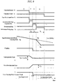
- FIG. 7 is a time chart showing a state change of the power transmission system at a time of shifting from the motor drive mode to the engine drive mode
- FIG. 8 is a time chart showing a state change of the power transmission system at a time of shifting from the engine drive mode to the motor drive mode. As shown in FIG.
- the state of the power transmission system becomes the engine direct-coupled phase E through: a synchronization phase A for synchronizing the revolution speeds of the inner ring 32 and the outer ring 31 of the coupling 26; a synchronization determining phase B for determining the synchronization of the revolution speed; a connection phase C for connecting the coupling 26 by carrying a current into the electromagnetic coil 37; and a connection-side-torque cooperation phase D for cooperating with the engine torque and the drive motor torque under the connection state of the coupling 26 and completing the connection thereof. Consequently, the shift to the engine running mode is finished.
- the vehicle When exceeding a speed of 80 km/h, the vehicle is set to be shifted from the motor drive mode to the engine drive mode.
- the value of the vehicle speed can be optionally set, and the vehicle speed shifted from the engine drive mode to the motor drive mode may be also set similarly, and hysteresis may be provided based on directions of the mode shift.
- the revolution speed of the power generating motor 21 is controlled based on a target revolution speed determined by: a revolution speed of the input-side shaft of the coupling 26 which is the same as the revolution speed of the power generating motor 21 at that time, that is, the engine speed; and the revolution speed of the post-connected power generating motor which is definitely determined by the vehicle speed and the revolution speed of the drive motor 12.
- the synchronization determining phase B it is determined whether the synchronization is established depending on whether a state, in which a difference between the revolution speed of the input-side shaft of the coupling 26, i.e., the revolution speed of the power generating motor 21 and the revolution speed of the output-side shaft, i.e., the engine-power transmission shaft 23 is in a predetermined error range, has passed for a predetermined time.
- the connection phase C power is supplied to the electromagnetic coil 37 to connect the coupling 26, and a predetermined delay time is set in view of an operating time of the coupling 26.
- the connection-side-torque cooperation phase D the engine torque is increased and the motor torque is decreased, whereby a smooth connecting operation can be performed without any shock caused in the shift. Accordingly, the coupling 26 is set to the direct-coupled phase E and the shift from the motor drive mode to the engine drive mode is completed.
- the revolution speed of the power generating motor 21 is controlled until the connection phase C is finished from the motor drive mode, and the power generating motor 21 is controlled in zero torque at a time of being shifted to the connection-side-torque cooperation phase D and the zero-torque control is executed also in the direct-coupled phase E.
- the state of the power transmission system is shifted to the motor drive mode via: a disconnection-side-torque cooperation phase F for cooperating with the engine torque and the drive motor torque and starting the coupling; a disconnection phase G for stopping carrying a current to the electromagnetic coil 37 and setting the coupling 26 at a disconnecting state; and a synchronization finishing phase H for providing a difference in revolution speed between the inner ring and the outer ring of the coupling 26.
- the engine torque is decreased and the motor torque is increased.
- the disconnection phase G in order to cancel the connection of the coupling 26, the supply of power to the coil 37 is stopped and a predetermined delay time is set in view of the operation time of the coupling 26.
- the synchronization finishing phase H the difference in rotation between the input-side shaft and the output-side shaft of the coupling 26 is provided, so that it is possible to securely cancel the connection even if elements of the coupling 26 corresponding to the mechanical clutch are engaged with each other.
- the power generating motor 21 is controlled in zero torque until the disconnection-side-torque cooperation phase F is finished from the direct-coupled phase E.
- the power generating motor 21 is shifted to the revolution-speed control and, in the motor drive mode, the revolution-speed control is executed.
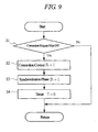
- FIG. 9 is a main flow chart showing a control algorithm of the coupling 26 in the above-mentioned power transmission system
- FIG. 10 is a flow chart showing a transition-control algorithm to each of the above-mentioned phases. If it is determined that a condition where the coupling 26 set in the connecting state is shifted to the engine drive mode is established, the connection request flag Fd is established based on the connection request signal. If this is determined in step S1 of FIG. 9, the connection control flag Fc is established in step S2 and the synchronization phase flag F1 is established in step S3 and a timer is reset in step S4.
- control routine is returned and a revolution speed Nge of the power generating motor 21 at that time is read and the revolution speed of the power generating motor 21 is set at a revolution speed Ngb of the power generating motor before establishment of the connection condition.
- each subroutine denoted by reference symbols "A" to "H" is executed.
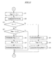
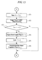
- FIGs. 11 to 18 are flow charts showing each of subroutines indicated by the reference symbols "A" to "H” in FIG. 10. If it is determined by the steps S10 and S11 shown in FIG. 10 that the mode is shifted to the synchronization phase A, a timer T is incremented in step S21 shown in FIG. 11 and a synchronization phase processing is executed in step S22. In this step S22, the target revolution speed Ngt of the power generating motor 21 is calculated, and the calculated revolution speed is instructed to the power generating motor 21.
- the target revolution speed Ngt of the power generating motor 21 is controlled by the engine 11, so that the target revolution speed Ngt is calculated based on a difference between the revolution speed before connection of the coupling 26 and the revolution speed after connection of the coupling 26 in accordance with the following formula.
- the revolution speed of the power generating motor 21 is controlled so that the revolution speed Ngb before the connection of the coupling coincides with a value obtained by multiplying the revolution speed of the drive motor 12 shown by the broken line by the speed reduction ratios of two gear trains, that is, with the revolution speed of the engine-power transmission shaft 23. Note that the revolution speed of the engine-power transmission shaft 23 coincides with the revolution speed of the inner ring 32 of the coupling 26.
- FIG. 5A is a characteristic diagram showing a revolution synchronization coefficient Ks.
- the coefficient Ks is changed as illustrated in accordance with progress of the synchronization phase A counted by the timer.
- step S23 it is determined whether the coupling connection request is cancelled, i.e., whether the connection request flag Fd is in failure at a time when the synchronization phase A is executed. If it is determined in the step S23 that the connection request is cancelled, the synchronization phase flag F1 is set to failure in step S24 and the timer T is rest in step S25 and the synchronization finishing phase flag F8 is established in step S26.
- step S27 it is determined in step S27 whether a preset synchronization phase time T1 has passed. If it is determined in the step S27 that the time T1 has not passed, the routine is returned. If it is determined that the time T1 has passed, the synchronization phase flag F1 is set to failure and the timer T is reset and the synchronization determining phase flag F2 is established (steps S28 to S30). By doing so, the mode is shifted to the synchronization determining phase B shown in FIG. 12.
- step S31 the timer T is incremented in step S31, and the synchronization determining phase processing is executed in step S32.
- the revolution speed of the power generating motor 21 is controlled, and the target revolution speed Ngt of the power generating motor 21 is calculated by the following formula and an instruction signal is sent to the power generating motor 21.
- Engine instruction torque TQet is set in the same manner as the synchronization phase A.
- Target Revolution Speed Ngt Nm ⁇ (Re / Rm).
- Nm is a revolution speed of the drive motor 12
- Re is a speed reduction ratio of the gear train in the engine-power transmission path
- Rm is a speed reduction ratio of the gear train in the motor-power transmission path.
- connection request flag Fd is in failure at a time when the synchronization determining phase processing is executed, the synchronization determining phase flag F2 is set to failure and the timer T is reset and the synchronization finishing phase flag F8 is established (steps S34 to S36). Meanwhile, if it is determined that the connection request flag Fd is still established, it is determined in step S37 whether the revolution speed error ⁇ N is larger than the maximum value ⁇ Na of the error. When it is determined in the step S37 that the revolution speed error ⁇ N is larger than the maximum value ⁇ Na, step S38 is executed and a rotation error flag Fs is set to failure. When it is determined that the revolution speed error ⁇ N is smaller than the maximum value ⁇ Na, the revolution error flag Fs is established in step S39.
- step S40 It is determined in step S40 whether the revolution error flag Fs is shifted to the establishment from the failure. If it is determined that it is shifted, a synchronization timer Ts is reset in step S41 and the timer is incremented in step S42. It is determined in step S43 whether the synchronization timer Ts passes continuously a synchronization determining time T2. If it is determined that it is continued, the revolution error flag Fs is set to failure, the synchronization determining phase flag F2 is set to failure and the timer T is reset and the connection phase flag F3 is established (steps S44 to S47).
- connection phase flag F3 is established in step S47, the connection signal is outputted and the timer T is incremented in step S51 and the connection phase processing is executed in step S52.
- the revolution speed of the power generating motor 21 is controlled, and the target revolution speed Ngt of the power generating motor is calculated by the following formula and the instruction signal is sent to the power generating motor 21.
- the engine instruction torque TQet is set in the same manner as the synchronization phase A.
- Target revolution speed Ngt Nm ⁇ (Re / Rm), where "Nm” is a revolution speed of the drive motor 12, “Re” is a speed reduction ratio of the gear train in the engine-power transmission path, and “Rm” is a speed reduction ratio of the gear train in the motor-power transmission path.
- step S53 It is determined in step S53 whether the rotations of the outer ring 31 and the inner ring 32 of the coupling 26 are in a synchronous state. This determination is executed based on whether the timer T is equal to a preset connection phase time T3. If the connection phase time T3 has passed, the connection phase flag F3 is set to failure and the timer T is reset and a connection-side-torque cooperation phase flag F4 is established (steps S54 to S56). If the connection-side-torque cooperation flag F4 is not established, the power generating motor 21 is controlled in zero torque.
- connection-side-torque cooperation phase D If the connection-side-torque cooperation phase D is executed, the timer T is incremented in step S61 and the connection-side-torque cooperation phase processing in step S62 is executed.
- the engine instruction torque TQet is calculated based on vehicle required torque TQb generated on the main shaft of the drive motor 12 by the following formula.
- Engine Instruction Torque TQet TQb ⁇ (Rm / Re) ⁇ Kon.
- “Kon” is a connection-side-torque cooperation coefficient
- the coefficient Kon is changed as shown in FIG. 5B in accordance with a procedure of the connection-side connecting phase processing counted by the timer.
- the engine instruction torque TQet is set within a range of "TQe ⁇ TQet ⁇ TQea”.
- “TQe” is an initial value of the torque-cooperation engine torque
- “TQea” is the maximum value of the engine torque and this value is set every engine rotation.
- a value of a throttle opening degree is calculated based on the engine instruction torque TQet and the engine revolution speed, and the throttle opening degree is electronically controlled and the engine torque is adjusted.
- the calculation of the engine instruction torque TQet may be carried out by the following formula in view of the power generation by the drive motor 12.
- Engine Instruction Torque TQet TQb ⁇ (Rm / Re) ⁇ Kon + TQg
- TQg is power generation torque on the crank shaft during the connection.
- drive-motor instruction torque TQm TQb - (TQet ⁇ Re / Rm)
- step S63 If it is determined in step S63 that the timer T becomes equal to a preset connection-side cooperation phase time T4, the connection-side phase flag F4 is set to failure and the timer T is reset and the engine connecting phase flag F5 is established.
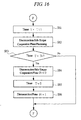
- step S71 If the engine direct-coupled phase E is established, the timer T is incremented in step S71 as shown in FIG. 15 and an engine direct-coupled phase in step S72 is executed and the power generating motor 21 is controlled in zero torque at this time.
- the engine instruction torque TQet and the drive-motor instruction torque TQm are calculated based on the vehicle required torque TQb generated on the drive motor shaft in accordance with the following formula.
- TQei indicates the minimum value of the engine torque
- TQea indicates the maximum value of the engine torque.
- the minimum value TQea of the engine torque is set every engine revolution speed.
- Engine Instruction Torque TQet TQb ⁇ Rm / Re + TQet.
- the shift from the motor drive mode to the engine drive mode is completed by executing a engine direct-coupled phase processing E, whereby the vehicle is driven by the engine 11. At this time, the power of the drive motor 12 may be transmitted to the vehicle.
- the engine drive mode is continued until the connection request is cancelled in step S73, that is, until "YES" is determined in the step S73.
- the engine direct-coupled phase flag F5 is set to failure and the timer T is reset and the disconnection-side-torque cooperation phase flag F6 is established (steps S74 to S76). Accordingly, the shift from the engine drive mode to the motor drive mode is started.
- Koff is a disconnection-side-torque cooperation coefficient, and the coefficient Koff is changed as shown in FIG. 6A depending on a procedure of the torque cooperation phase F counted by the timer. Further, the engine instruction torque TQet is set within a range of "TQ ⁇ TQet ⁇ TQea”. In this inequality, “TQe” is an initial value of torque-cooperation engine torque, and “TQea” is the maximum value of the engine torque and this value is set every engine rotation.
- the drive-motor instruction torque TQm is calculated based on the vehicle required torque TQb and the engine instruction torque TQet in accordance with the following formula, and the instruction signal is outputted to the drive motor 12.
- Drive-Motor Instruction Torque TQm TQb - (TQet ⁇ Re / Rm).
- step S83 If it is determined in step S83 that the timer T becomes equal to a preset disconnection-side cooperation phase time T6, the disconnection-side-torque phase flag F6 is set to failure and the timer T is reset and the disconnection phase flag F7 for disconnecting the coupling 26 is established (steps S84 to S86).
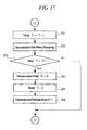
- step S86 of FIG. 16 If a disconnection phase flag F7 is established in step S86 of FIG. 16, the timer T is incremented per predetermined control period in step S91 shown in FIG. 17 and the disconnection-side phase processing is executed in step S92.
- the revolution speed of the power generating motor 21 is controlled, the target revolution speed Ngt of the power generating motor 21 is calculated in accordance with the following formula, and the instruction signal is sent to the power generating motor 21.
- Target Revolution Speed Ngt Nm ⁇ (Re / Rm).
- the engine instruction torque TQet at this time is set in the same manner as the synchronization phase A. If it is determined in step S93 that the timer T becomes equal to a preset disconnection phase time T7, the disconnection phase flag F7 is set to failure and the timer T is reset and the synchronization finishing phase flag F8 is established (steps S94 to S96).
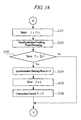
- step S96 of FIG. 17 If the synchronization finishing phase flag F8 is established in step S96 of FIG. 17, the revolution speed Nge of the power generating motor 21 is read and this value is set to the power generating revolution speed Ngr at a time of disconnecting the coupling 26 and the timer T is incremented in step S101 of FIG. 18, and a synchronization finishing phase processing in step S102 is executed.
- the target revolution speed Ngt of the power generating motor 21 is calculated in accordance with the following formula and is instructed to the power generating motor 21.
- Target Revolution Speed Ngt (Ngr - Ngc) ⁇ Ke + Ngc.
- Ngc is a return revolution speed
- Ke is a revolution synchronization finishing coefficient.
- the return revolution speed Ngc is calculated as a function of the power generating revolution speed Ngr at a time of disconnecting the coupling, as shown in FIG. 6B
- the revolution synchronization finishing coefficient Ke is calculated as a function of time in accordance with a proceeding time of the synchronization finishing phase, as shown in FIG. 6C.
- step S103 If it is determined in step S103 that the timer T becomes equal to a preset synchronization finishing phase time T8, a synchronization finishing phase flag F8 is set to failure and the timer T is reset and a connecting control flag Fc is established (steps S104 to S106).
- the present invention is not limited to the above-mentioned embodiment and can be variously modified and altered without departing from the gist thereof.
- the coupling 26 is not limited to illustrated types, and any coupling without being limited to the illustrated coupling can be employed as far as being shifted to a state of transmitting the rotation and a state of cutting off the transmission by an electromagnet.
Landscapes
- Engineering & Computer Science (AREA)
- Chemical & Material Sciences (AREA)
- Combustion & Propulsion (AREA)
- Transportation (AREA)
- Mechanical Engineering (AREA)
- Automation & Control Theory (AREA)
- Electric Propulsion And Braking For Vehicles (AREA)
- Control Of Vehicle Engines Or Engines For Specific Uses (AREA)
- Hybrid Electric Vehicles (AREA)
- Control Of Transmission Device (AREA)
Applications Claiming Priority (2)
| Application Number | Priority Date | Filing Date | Title |
|---|---|---|---|
| JP2003361417A JP2005130564A (ja) | 2003-10-22 | 2003-10-22 | ハイブリッド車両の制御装置 |
| JP2003361417 | 2003-10-22 |
Publications (2)
| Publication Number | Publication Date |
|---|---|
| EP1526023A2 true EP1526023A2 (de) | 2005-04-27 |
| EP1526023A3 EP1526023A3 (de) | 2006-01-11 |
Family
ID=34386493
Family Applications (1)
| Application Number | Title | Priority Date | Filing Date |
|---|---|---|---|
| EP04256438A Withdrawn EP1526023A3 (de) | 2003-10-22 | 2004-10-20 | Steuervorrichtung für Hybridfahrzeug |
Country Status (3)
| Country | Link |
|---|---|
| US (1) | US7226383B2 (de) |
| EP (1) | EP1526023A3 (de) |
| JP (1) | JP2005130564A (de) |
Cited By (5)
| Publication number | Priority date | Publication date | Assignee | Title |
|---|---|---|---|---|
| EP2067646A3 (de) * | 2007-12-04 | 2010-03-03 | Ford Global Technologies, LLC | Generatorleistungsbasierte Kaltstartstrategie |
| WO2010089247A1 (de) * | 2009-02-09 | 2010-08-12 | Zf Friedrichshafen Ag | Verfahren zum ankoppeln einer brennkraftmaschine eines parallel-hybrid-antriebsstranges |
| EP3000640A1 (de) * | 2014-09-23 | 2016-03-30 | Hyundai Motor Company | System und Verfahren zur Steuerung des Aufladens eines Hybridfahrzeugs |
| CN107234964A (zh) * | 2016-03-29 | 2017-10-10 | 上海中科深江电动车辆有限公司 | 混合动力装置 |
| CN113085835A (zh) * | 2021-05-13 | 2021-07-09 | 潍柴动力股份有限公司 | 应用于混合动力汽车的驱动方法、设备、程序产品 |
Families Citing this family (27)
| Publication number | Priority date | Publication date | Assignee | Title |
|---|---|---|---|---|
| JP4874604B2 (ja) * | 2005-09-09 | 2012-02-15 | Hoya株式会社 | 超音波モータ |
| US8417427B2 (en) * | 2005-11-15 | 2013-04-09 | Stridsberg Powertrain Ab | Hybrid vehicle with soft shafts |
| JP4396661B2 (ja) * | 2006-05-26 | 2010-01-13 | 日産自動車株式会社 | ハイブリッド車両のクラッチ締結制御装置 |
| JP4421603B2 (ja) * | 2006-12-01 | 2010-02-24 | 本田技研工業株式会社 | モータ制御方法およびモータ制御装置 |
| JP5109467B2 (ja) * | 2007-05-02 | 2012-12-26 | 日産自動車株式会社 | ハイブリッド車両の駆動制御装置 |
| US8423214B2 (en) | 2009-09-15 | 2013-04-16 | Kpit Cummins Infosystems, Ltd. | Motor assistance for a hybrid vehicle |
| CN102596672B (zh) | 2009-09-15 | 2015-03-04 | Kpit技术有限责任公司 | 根据预测的驱动变化向一种混合动力交通工具提供的引擎辅助 |
| MX2012003114A (es) | 2009-09-15 | 2012-06-19 | Kpit Cummins Infosystems Ltd | Metodo para convertir un vehiculo en un vehiculo hibrido. |
| JP5926182B2 (ja) | 2009-09-15 | 2016-05-25 | ケーピーアイティ テクノロジーズ リミテッド | ユーザ入力に基づくハイブリッド車のモータ補助 |
| JP2011223681A (ja) * | 2010-04-06 | 2011-11-04 | Toyota Motor Corp | 回生制動トルクの制御装置 |
| US8636620B2 (en) | 2010-10-28 | 2014-01-28 | Jatco Ltd | Automatic transmission |
| JP5383626B2 (ja) | 2010-11-01 | 2014-01-08 | ジヤトコ株式会社 | 車両の制御装置 |
| JP5693151B2 (ja) | 2010-11-01 | 2015-04-01 | ジヤトコ株式会社 | 車両の制御装置 |
| JP5496855B2 (ja) * | 2010-11-01 | 2014-05-21 | ジヤトコ株式会社 | 車両の制御装置 |
| JP5693152B2 (ja) | 2010-11-01 | 2015-04-01 | ジヤトコ株式会社 | 車両の油圧制御装置 |
| JP5496854B2 (ja) | 2010-11-01 | 2014-05-21 | ジヤトコ株式会社 | 車両の制御装置 |
| JP5501937B2 (ja) | 2010-11-02 | 2014-05-28 | ジヤトコ株式会社 | ハイブリッド車両の制御装置 |
| JP5501260B2 (ja) | 2011-02-03 | 2014-05-21 | ジヤトコ株式会社 | 車両の制御装置 |
| US8628451B2 (en) * | 2011-06-16 | 2014-01-14 | GM Global Technology Operations LLC | Method and apparatus for executing a shift in a powertrain system |
| JP6019732B2 (ja) | 2012-05-15 | 2016-11-02 | 三菱自動車工業株式会社 | ハイブリッド自動車の制御装置 |
| JP6439324B2 (ja) * | 2014-08-28 | 2018-12-19 | アイシン精機株式会社 | 車両の制御装置 |
| JP6321580B2 (ja) * | 2015-06-05 | 2018-05-09 | 日立建機株式会社 | 作業機械 |
| JP7663396B2 (ja) | 2021-03-31 | 2025-04-16 | 株式会社Subaru | 車両用制御装置 |
| CN114017479A (zh) * | 2021-11-30 | 2022-02-08 | 惠州兴为智能科技有限公司 | 一种力量训练器械的变速装置 |
| KR20230132028A (ko) * | 2022-03-07 | 2023-09-15 | 현대자동차주식회사 | 하이브리드 자동차 및 그를 위한 모터 구동 장치 |
| WO2026010541A1 (en) * | 2024-07-04 | 2026-01-08 | Husqvarna Ab | Hybrid driveline and method for a floor saw arranged with control unit for controlling spindle rotation |
| SE2450763A1 (en) * | 2024-07-04 | 2026-01-05 | Husqvarna Ab | A hybrid driveline with a gearbox synchronization function |
Family Cites Families (11)
| Publication number | Priority date | Publication date | Assignee | Title |
|---|---|---|---|---|
| JP2967103B2 (ja) * | 1993-05-24 | 1999-10-25 | 株式会社エクォス・リサーチ | ハイブリット車輌 |
| DE19814402C2 (de) * | 1998-03-31 | 2000-03-23 | Isad Electronic Sys Gmbh & Co | Antriebssystem für ein Kraftfahrzeug sowie Verfahren zum Betreiben desselben |
| JP3336951B2 (ja) * | 1998-04-28 | 2002-10-21 | 株式会社日立製作所 | 自動車の動力伝達装置 |
| JP3286619B2 (ja) | 1999-04-06 | 2002-05-27 | 株式会社日立製作所 | 自動車の動力伝達装置 |
| EP1125781B1 (de) * | 2000-01-24 | 2004-03-24 | Hino Jidosha Kabushiki Kaisha | Hybridfahrzeug |
| US7185722B1 (en) * | 2000-02-04 | 2007-03-06 | Hitachi, Ltd. | Power transmission apparatus of motor vehicles |
| JP3719127B2 (ja) * | 2000-10-25 | 2005-11-24 | トヨタ自動車株式会社 | NOx排出抑止型ハイブリッド車 |
| JP3852321B2 (ja) * | 2001-10-22 | 2006-11-29 | トヨタ自動車株式会社 | クランキング支持トルク増大手段付きhv駆動構造および方法 |
| DE10204981A1 (de) * | 2002-02-06 | 2003-08-14 | Daimler Chrysler Ag | Verfahren zum Betrieb eines Antriebssystems für ein Kraftfahrzeug |
| JP3715272B2 (ja) * | 2002-11-21 | 2005-11-09 | トヨタ自動車株式会社 | 車両の動力伝達装置 |
| JP3700710B2 (ja) * | 2003-05-09 | 2005-09-28 | 日産自動車株式会社 | ハイブリッド車両の駆動制御装置 |
-
2003
- 2003-10-22 JP JP2003361417A patent/JP2005130564A/ja active Pending
-
2004
- 2004-10-20 EP EP04256438A patent/EP1526023A3/de not_active Withdrawn
- 2004-10-20 US US10/968,099 patent/US7226383B2/en not_active Expired - Fee Related
Cited By (12)
| Publication number | Priority date | Publication date | Assignee | Title |
|---|---|---|---|---|
| EP2067646A3 (de) * | 2007-12-04 | 2010-03-03 | Ford Global Technologies, LLC | Generatorleistungsbasierte Kaltstartstrategie |
| US8020652B2 (en) | 2007-12-04 | 2011-09-20 | Ford Global Technologies, Llc | Generator power-based cold start strategy |
| US8215429B2 (en) | 2007-12-04 | 2012-07-10 | Ford Global Technologies Llc | Generator power-based cold start strategy |
| WO2010089247A1 (de) * | 2009-02-09 | 2010-08-12 | Zf Friedrichshafen Ag | Verfahren zum ankoppeln einer brennkraftmaschine eines parallel-hybrid-antriebsstranges |
| US8529400B2 (en) | 2009-02-09 | 2013-09-10 | Zf Friedrichshafen Ag | Method for coupling an internal combustion engine of a parallel-hybrid drive train |
| EP3000640A1 (de) * | 2014-09-23 | 2016-03-30 | Hyundai Motor Company | System und Verfahren zur Steuerung des Aufladens eines Hybridfahrzeugs |
| CN105730434A (zh) * | 2014-09-23 | 2016-07-06 | 现代自动车株式会社 | 用于控制混合动力车的充电的系统和方法 |
| US9387755B2 (en) | 2014-09-23 | 2016-07-12 | Hyundai Motor Company | System and method for controlling charging of hybrid vehicle |
| CN105730434B (zh) * | 2014-09-23 | 2020-01-10 | 现代自动车株式会社 | 用于控制混合动力车的充电的系统和方法 |
| CN107234964A (zh) * | 2016-03-29 | 2017-10-10 | 上海中科深江电动车辆有限公司 | 混合动力装置 |
| CN107234964B (zh) * | 2016-03-29 | 2020-03-13 | 上海中科深江电动车辆有限公司 | 混合动力装置 |
| CN113085835A (zh) * | 2021-05-13 | 2021-07-09 | 潍柴动力股份有限公司 | 应用于混合动力汽车的驱动方法、设备、程序产品 |
Also Published As
| Publication number | Publication date |
|---|---|
| JP2005130564A (ja) | 2005-05-19 |
| EP1526023A3 (de) | 2006-01-11 |
| US20050090366A1 (en) | 2005-04-28 |
| US7226383B2 (en) | 2007-06-05 |
Similar Documents
| Publication | Publication Date | Title |
|---|---|---|
| EP1526023A2 (de) | Steuervorrichtung für Hybridfahrzeug | |
| EP2192013B1 (de) | Antriebsvorrichtung für ein fahrzeug | |
| EP2412553B1 (de) | Antriebsvorrichtung für ein fahrzeug | |
| US6540642B2 (en) | Vehicle control system and vehicle control method | |
| JP3682964B2 (ja) | 車両用駆動装置 | |
| RU2540197C1 (ru) | Устройство передачи мощности транспортного средства | |
| US6715572B2 (en) | Control system for hybrid vehicle | |
| CN102328578B (zh) | 用于机动车辆的驱动系统及具有这种驱动系统的机动车辆 | |
| EP2636566A1 (de) | Hybridantriebsvorrichtung für ein fahrzeug | |
| EP1669236B1 (de) | Gangschaltsteuervorrichtung für hybrid-elektro-fahrzeug | |
| EP1002689A2 (de) | Regelvorrichtung und Regelverfahren für ein Hybrid-Fahrzeug | |
| US20110098151A1 (en) | Hybrid drive train for a motor vehicle and method for operating the hybrid drive train | |
| KR20010075674A (ko) | 이중 클러치를 구비한 자동차용 변속기와 이 변속기를구동시키기 위한 구동 방법 | |
| US8496560B2 (en) | Starting control system for engines | |
| US20050202929A1 (en) | Method and apparatus for engaging engine clutch for hybrid transmission | |
| JP2004353781A (ja) | 車輌用駆動装置 | |
| JP3826637B2 (ja) | 車両の回生制動装置 | |
| JP2010076625A (ja) | ハイブリッド車両 | |
| JP2002114063A (ja) | ハイブリッド車両用動力伝達装置 | |
| JP2011223681A (ja) | 回生制動トルクの制御装置 | |
| CN103180190B (zh) | 车辆的动力传递控制装置 | |
| JP5109929B2 (ja) | 内燃機関始動制御装置 | |
| US20240092342A1 (en) | Vehicle control device | |
| WO2007043875A1 (en) | Vehicle with two parallel drivelines | |
| US12472933B2 (en) | Vehicle drive device |
Legal Events
| Date | Code | Title | Description |
|---|---|---|---|
| PUAI | Public reference made under article 153(3) epc to a published international application that has entered the european phase |
Free format text: ORIGINAL CODE: 0009012 |
|
| AK | Designated contracting states |
Kind code of ref document: A2 Designated state(s): AT BE BG CH CY CZ DE DK EE ES FI FR GB GR HU IE IT LI LU MC NL PL PT RO SE SI SK TR |
|
| AX | Request for extension of the european patent |
Extension state: AL HR LT LV MK |
|
| PUAL | Search report despatched |
Free format text: ORIGINAL CODE: 0009013 |
|
| AK | Designated contracting states |
Kind code of ref document: A3 Designated state(s): AT BE BG CH CY CZ DE DK EE ES FI FR GB GR HU IE IT LI LU MC NL PL PT RO SE SI SK TR |
|
| AX | Request for extension of the european patent |
Extension state: AL HR LT LV MK |
|
| AKX | Designation fees paid | ||
| 17P | Request for examination filed |
Effective date: 20060612 |
|
| RBV | Designated contracting states (corrected) |
Designated state(s): DE |
|
| REG | Reference to a national code |
Ref country code: DE Ref legal event code: 8566 |
|
| 17Q | First examination report despatched |
Effective date: 20091111 |
|
| STAA | Information on the status of an ep patent application or granted ep patent |
Free format text: STATUS: THE APPLICATION IS DEEMED TO BE WITHDRAWN |
|
| 18D | Application deemed to be withdrawn |
Effective date: 20100323 |