EP1526030B1 - Dispositif et procédé de commande pour un réseau électrique de véhicule avec diagnose de la détérioration d'une batterie - Google Patents
Dispositif et procédé de commande pour un réseau électrique de véhicule avec diagnose de la détérioration d'une batterie Download PDFInfo
- Publication number
- EP1526030B1 EP1526030B1 EP04023250A EP04023250A EP1526030B1 EP 1526030 B1 EP1526030 B1 EP 1526030B1 EP 04023250 A EP04023250 A EP 04023250A EP 04023250 A EP04023250 A EP 04023250A EP 1526030 B1 EP1526030 B1 EP 1526030B1
- Authority
- EP
- European Patent Office
- Prior art keywords
- battery
- power supply
- deterioration
- detected
- automotive vehicle
- Prior art date
- Legal status (The legal status is an assumption and is not a legal conclusion. Google has not performed a legal analysis and makes no representation as to the accuracy of the status listed.)
- Expired - Lifetime
Links
- 230000006866 deterioration Effects 0.000 title claims description 84
- 238000000034 method Methods 0.000 title claims description 27
- 239000002826 coolant Substances 0.000 claims description 17
- 239000003792 electrolyte Substances 0.000 claims description 15
- 239000007858 starting material Substances 0.000 claims description 15
- 230000002401 inhibitory effect Effects 0.000 claims description 3
- 238000003745 diagnosis Methods 0.000 description 7
- 238000001514 detection method Methods 0.000 description 4
- 238000010248 power generation Methods 0.000 description 4
- 238000009825 accumulation Methods 0.000 description 3
- 230000003247 decreasing effect Effects 0.000 description 2
- 230000006870 function Effects 0.000 description 2
- 230000003190 augmentative effect Effects 0.000 description 1
- 238000010586 diagram Methods 0.000 description 1
- 239000000446 fuel Substances 0.000 description 1
- 238000011084 recovery Methods 0.000 description 1
- 230000004044 response Effects 0.000 description 1
Images





Classifications
-
- G—PHYSICS
- G01—MEASURING; TESTING
- G01R—MEASURING ELECTRIC VARIABLES; MEASURING MAGNETIC VARIABLES
- G01R31/00—Arrangements for testing electric properties; Arrangements for locating electric faults; Arrangements for electrical testing characterised by what is being tested not provided for elsewhere
- G01R31/36—Arrangements for testing, measuring or monitoring the electrical condition of accumulators or electric batteries, e.g. capacity or state of charge [SoC]
- G01R31/392—Determining battery ageing or deterioration, e.g. state of health
-
- G—PHYSICS
- G01—MEASURING; TESTING
- G01R—MEASURING ELECTRIC VARIABLES; MEASURING MAGNETIC VARIABLES
- G01R31/00—Arrangements for testing electric properties; Arrangements for locating electric faults; Arrangements for electrical testing characterised by what is being tested not provided for elsewhere
- G01R31/36—Arrangements for testing, measuring or monitoring the electrical condition of accumulators or electric batteries, e.g. capacity or state of charge [SoC]
- G01R31/382—Arrangements for monitoring battery or accumulator variables, e.g. SoC
Definitions
- the present invention relates to control apparatus and method for vehicle equipped power supply and particularly relates to a technique to diagnose a deterioration of a vehicular battery with a high accuracy although an inexpensive structure.
- a battery is mounted in a vehicle as a power supply for a starter to perform a cranking and other electrical parts.
- the battery is chargeable or dischargeable and it is usual practice that an output voltage level (a charged state of the battery) is controlled to a predetermined level by controlling a generated power of an alternator in accordance with an actual charged state of the battery and in accordance with a driving state of an engine.
- an electric motor is disposed as a drive source except the engine, this electric motor is used as the starter to enable the cranking.
- DE 198 31 723 A1 discloses a control apparatus and a control method for a power supply equipped in an automotive vehicle including an engine, a stator, a battery and a generator.
- a battery voltage detecting section is provided detecting a terminal voltage of the battery and a charge current detecting section is provided detecting a charge current supplied by the generator.
- a deterioration determining section determines a degree of deterioration of the battery on the basis of the battery voltage detected after the power supply is turned on.
- DE 43 41 826 A1 discloses a method for determining the state of charge of a battery incorporated in an automotive vehicle.
- the vehicle includes an engine, a starter, a battery and a generator.
- a voltage detector detects the voltage of the battery
- a current detector detects the current of the battery for determining a degree of the deterioration of the battery, wherein the time, where the dead centers are passed, are included in the determination of degree of deterioration.
- a map including the charge voltage and the temperature of the battery is used for determining the state of charge of the battery.
- Fig.1 is a block diagram of a control apparatus for a vehicle equipped power supply in a preferred embodiment according to the present invention.
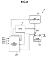
- Fig. 2 is a configuration of the control apparatus for the vehicle equipped power supply in the preferred embodiment shown in Fig. 1.
- Fig. 3 is a flowchart of a power generation control procedure in the control apparatus shown in Fig. 2.
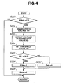
- Fig. 4 is a flowchart of a deterioration diagnostic routine executed by the control apparatus shown in Fig. 2.
- Fig. 5 is a map view representing a threshold voltage Vs.
- Fig. 6 is a flowchart of a diagnostic ascertained routine executed by the control apparatus shown in Fig. 2.
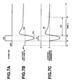
- Figs. 7A, 7B, and 7C integrally show a timing chart representing a battery voltage Vs and charge-discharge current Ic.
- Fig. 8 is a flowchart representing another diagnostic routine in another preferred embodiment of the control apparatus according to the present invention.
- Figs. 1 and 2 show a structure of a vehicle equipped power supply (or simple referred to as a power supply) in a preferred embodiment of a vehicular power supply control apparatus according to the present invention.
- Power supply 1 is constituted by power supply for various kinds of electrical parts 102 and 111 through 113 equipped in the vehicle.
- An engine (engine body) 101 constitutes a drive source of this automotive vehicle.
- a starter 103 is installed as a starting motor to perform an engine cranking during a start of engine 101.
- an alternator 103 is installed in engine 1 as a generator operated with a power of engine 1.
- Alternator 103 is operated in response to a command signal from a control unit 201 (hereinafter, referred to as C/U) and generates an electric power in accordance with the command signal.
- a battery 104 (BATT) is chargeable and dischargeable and reserves the power generated by alternator 104.
- the generated power of alternator 103 and discharge power of battery 104 are supplied to starter 102 and other electrical parts 111 through 113.
- the other electrical parts include head lamps 111, a blower 112 of a vehicular air conditioner, and a defogger 113.
- Control unit 201 receives a detection signal of a coolant temperature sensor 301 detecting a coolant temperature Tw of engine 1 and electrolyte temperature sensor 302 to detect an electrolyte temperature Te of battery 104, and a detection signal of a current sensor 303 to detect a charge-and-discharge current Ic of battery 104 (refer to Fig. 2).
- Control unit 201 is connected to battery 104 and has a function to detect a terminal voltage (namely, the battery voltage) Vb of battery 104.
- control unit 201 receives a start switch signal SWstr from a start switch 304 and an ignition switch signal SWign from an ignition switch 305.
- Control unit 201 controls a generation operation of alternator 103 on the basis of the received detection signals.
- control unit (C/U) 201 detects a charged state SOC (State Of Charge) of battery 104, controls the generated power of alternator 104 in accordance with the detected SOC, and supplies the generated power of alternator 103 and the discharge power of battery 104 to the electrical parts 102 and 111 through 113.
- control unit 201 charges the generated power of alternator 103 into battery 104 and controls the charged state of battery 104 to a predetermined level.
- control unit 201 varies the generated power of alternator 103 in accordance with the charged state of battery 104, diagnoses a deterioration of battery 104, and varies the generated power of alternator 103 in accordance with the charged state of battery 104.
- Fig. 3 shows a flowchart of a power generation control routine. This routine is executed for each of predetermined times after the ignition switch is turned on.
- control unit 201 determines whether a deterioration determination (judgment) flag Fjdg is 0 or not. If this flag indicates 0 (yes), the routine goes to a step S102. If this flag indicates not 0 at step S101, the routine goes to a step S103.
- This deterioration determination flag Fjdg is ordinarily set to 0. However, as will be described later, when control unit 201 determines that the deterioration degree of battery 104 has reached to a predetermined level, this flag Fjdg is set to " 1 ".
- control unit 201 sets target level tSOC of the charged state of battery 104 to a predetermined value tSOCi.
- a target level tSOC of the charged state of battery 104 is set to a value which is a subtraction of a predetermined value a from tSOC.
- the deterioration of battery 104 is advanced.
- target level tSOC is reduced by the reduction in the charge capacity so as to prevent an excessive charge.
- control unit 201 detects the charged state (SOC: State Of Charge) of battery 104.
- the charged state (SOC) is an accumulation of the charge-and-discharge current Ic of battery 104 (during the charge, this value is positive and, during the discharge, this value is negative) and approximated to the calculated accumulated value of ⁇ Ic.
- control unit 201 determines whether the detected SOC has reached to target level tSOC. If control unit 201 determines that the detected SOC has reached to target level tSOC, the routine goes to a step S107. If not reached (No) at step S105, the routine goes to a step S106. At step S106, control unit 201 determines that the charged state of battery 104 has not reached to target level tSOC and it is necessary to charge and sets a generated voltage Vg of alternator 103 is a relatively large predetermined value of tVgh.
- step S107 the charged state of battery 104 has reached to a target level tSOC.
- generated voltage Vg of alternator 103 is set to a predetermined value tVgl smaller than tVgh and supplies the discharge power of battery 104 mainly to the power of electrical parts 102, 111 through 113. It is noted that predetermined values of tVgh and tVgl is increased or decreased in accordance with a magnitude of an electrical load (in accordance with an operating state of any one or more of the electrical parts).
- Fig. 4 is a flowchart of a deterioration diagnosis routine. This routine is executed for each of the predetermined times after the ignition switch is turned on.
- control unit 201 determines whether starter switch signal SWstr is turned to " 1 ". If it is turned to " 1 ", start switch is turned on and the routine goes to a step S202. If not turned to " 1 ", the present routine is ended. It is noted that, in this embodiment, as a simple method of determining whether it is the cranking time or after the cranking, the value of start switch signal SWstr is referred to.
- control unit 201 determines whether a complete burning is ended and, according to the result of this determination, control unit 201 may determine whether it is during the cranking.
- control unit 201 reads battery voltage Vb.
- control unit 201 detects the voltage determination value Vj.
- the explanation is made with reference to Figs. 7A through 7C.
- Figs. 7A through 7C show variations in the battery voltage Vb and charge-and-discharge current Ic during the start of engine 1.
- Battery voltage Vb is reduced (time t1), first, when ignition switch is turned on.
- the discharge power of battery 104 is consumed as the electrical power of various kinds of control units including control unit 201.
- the start switch is turned on, the cranking is started (time t2) by means of a starter 102.
- the large current discharge occurs from battery 104 is generated so that battery voltage Vb is greatly reduced.
- alternator 103 starts the generation upon receipt of the charged state (SOC) of battery due to the large current discharge.
- the generated power of alternator 103 is supplied to the charge of battery 104.
- the charge-and-discharge current Ic thereafter, peaks and is decreased due to the recovery of the charged state SOC.
- a voltage determination value Vj a minimal value of battery voltage Vb during the cranking (hereinafter, referred to as a voltage minimal value) is adopted as voltage determination value Vj.
- control unit 201 sets threshold value Vs. Threshold value Vs searches a map (shown in Fig. 5) to which vs is allocated in accordance with coolant temperature Tw and electrolyte temperature Te. As Tw is low and Te is low, Vs is set to a smaller value.
- Tw coolant temperature
- Te electrolyte temperature
- Vs is set to a smaller value.
- a slide friction within engine 1 is large.
- the reduction in battery voltage Vb due to the cranking is large.
- the internal resistance of battery 104 is large and, as compared with the high electrolyte temperature, the output itself of battery 104 is small.
- control unit 201 determines whether the detected Vj is equal to or below the set Vs. If Vj is equal to or low than Vs (Yes) at step S205, the routine goes to a step S206. If Vj > Vs (No) at step S205, the routine goes to a step S207.
- Vb As a characteristic of battery voltage Vb, as the deterioration becomes advanced, the reduction in the battery voltage 104 due to the large current discharge becomes large. Hence, when voltage minimal value Vm is equal to or below threshold value Vs, control unit 201 can determine that the deterioration degree of battery 104 has reached to a predetermined level.
- deterioration determination flag Fjdg is set to “ 1 ".
- deterioration determination flag Fjdg is reset to " 0 ".
- end determination flag Pend is set to " 1 ". It is noted that end determination flag Fend is switched to 0 when the final determination on the deterioration is made at the subsequent diagnosis ascertaining routine.
- voltage minimal value Vm during the cranking is adopted as voltage determination value Vj.
- the calculated ⁇ v or average value AVEv is compared with the corresponding threshold value. If either ⁇ v or AVEv is equal to or below the threshold value, control unit 201 determines that the deterioration degree has reached to a predetermined level.
- Fig. 6 shows a flowchart of the diagnosis ascertaining routine.
- This routine is executed from each of the predetermined times after the ignition switch is turned on.
- control unit 201 determines whether start switch signal SWstr is at a If 0 ". If " 0 " (Yes) at step S301, the routine goes to a step S302. If not “ 0 " (No) at step S301, the routine is ended.
- control unit 201 determines if end determination flag Fend is at a " 1 ". If this flag state is at " 1 ", control unit 201 determines that the determination of the deterioration is ended at the deterioration diagnosis routine and the cranking is ended and the routine goes to a step S303. If not " 1 ", this routine is ended.
- control unit 201 detects the operation state of the electrical parts (namely, a magnitude of the electrical load) and determines if the detected magnitude of the electrical load is smaller than a predetermined value. If the magnitude of the electrical load is smaller than the predetermined value (yes) at step S303, the routine goes to a step S304. If the magnitude thereof is equal to or larger than the predetermined value (No) at step S303, this routine is ended.
- a cause of the reduction in battery voltage Vb during the cranking includes the electrical load other than that due to the cranking. There is a possibility that the determination takes the error.
- control unit 201 reads the charge-discharge current Ic.
- control unit 201 detects current determination value Ij.
- a maximal value Ip of a charge-and-discharge current Ic after the cranking is adopted as the current determination value Ij (refer to Figs. 7A through 7C).
- control unit 201 sets a threshold current Is. This threshold current Is may be a constant.
- control unit 307 determines if the detected Ij is equal to or below set Is. If Ij is equal to or below set Is (Yes), the routine goes to a step S309. If Ij is larger than Is (No), the routine goes to a step S308. In a state in which the deterioration of battery 104 is advanced, the internal resistance of battery 104 is augmented. Hence, the charge-and-discharge current (specifically, charge current) Ic when the generated power of alternator 103 is constant is made small.
- control unit 201 can determine that the large reduction of battery voltage Vb during the cranking is caused by the deterioration of battery 104 under a sufficient reliability.
- electromotive force E0 is reduced when the charged state (SOC) of battery 104 is low.
- voltage determination value Vj such as voltage minimal value Vm is reduced so that the deterioration is determined to occur (refer to step S206).
- the charge-and-discharge current Ic after the start of the power generation is increased as compared with the high charged state.
- control unit determines that current determination value Ij is larger than threshold current Is, an erroneous determination of the deterioration due to the reduction of the charged state SOC can be prevented.
- control unit 201 sets deterioration determination flag FJdg to "0".
- control unit 201 sets end determination flag Fend to " 0 ".
- current maximal value Ip after the cranking is adopted as current determination value Ij.
- the calculated ⁇ I or AVEi is compared with their respective threshold values. If either ⁇ I or AVEi is larger than the corresponding threshold value, control unit 201 may set deterioration determination flag Fjdg to 0 (step S308).
- step S202 in the flowchart of Fig. 2 constitutes battery voltage detecting means (section)
- step S304 in the flowchart shown in Fig. 6 constitutes charged current detecting means (section)
- the whole flowcharts shown in Figs. 4 and 6 constitute deterioration determining means (section)
- step S303 in the flowchart shown in Fig. 6 constitutes determination inhibiting means (section)
- step S104 in the flowchart shown in Fig. 3 constitutes charge state detecting means (section)
- all steps except step S104 constitutes charged state controlling means (section).
- the result of diagnosis carried out with a high accuracy is reflected on a control of the charged state of battery 104.
- target level tSOC in the charged state is set to be lowered.
- an excessive charge can be prevented and a wasteful power generation by means of alternator 103 can be avoided, and a fuel consumption of engine 1 can be saved.
- Fig. 8 shows a flowchart of the deterioration determination routine in another preferred embodiment of the control apparatus according to the present invention.
- control unit 201 determines whether start switch signal SWstr is turned to " 1 ". If SWstr is at a " 1 " (Yes), the routine goes to a step S402. If SWstr is not at a " 1 " (No), the routine is ended.
- control unit 201 reads battery voltage Vb.
- control unit 201 detects the minimal value of battery voltage Vb during the cranking, namely, voltage minimal value Vm.
- Predetermined value b has a reversed characteristic to the above-described threshold value Vs such that, as coolant temperature Tw becomes high and electrolyte temperature Te becomes high, predetermined value b is set to become small so that a subtraction value of MAX - b has the same characteristic as threshold value Vs.
- control unit 201 sets deterioration determination flag Fjdg to " 1 ".
- control unit 201 resets deterioration determination flag Fjdg to " 0 ".
- control unit 201 sets end determination flag Fend to " 1 " and the deterioration diagnosis at this routine is ended.
- diagnosis ascertaining routine may be the same as Fig. 6.
- step S402 of the flowchart shown in Fig. 8 constitutes battery voltage detecting means (section) and the whole flowchart (except steps S402, S303, and S304) shown in Figs. 8 and 6 constitute deterioration determining means (section) .
- the maximum value of voltage minimal value Vm detected until the previously detected is held as voltage stored value MAX, the presently detected voltage minimal value Vm is compared with the voltage stored value MAX to diagnose the deterioration of battery 104.
- a battery voltage Vb1 at a time point at which the ignition switch is turned on may be adopted in addition to voltage minimal value during the cranking as the voltage determination value Vj as appreciated from Figs. 7A through 7C. If this battery voltage Vb1 is equal to or below the predetermined value, control unit determines that the deterioration degree of battery 104 has reached to the predetermined level. Then, as described above, a case where alternator 103 is adopted as the generator has been described. In a hybrid vehicle, an electric motor having a rotational axle linked to an engine crankshaft may be adopted as the generator. This electric motor may be used as the starter of engine 101. It is noted that a meaning that the degree of the deterioration of the battery has reached to a predetermined level is the same that the battery requires an appropriate charge.
Landscapes
- Physics & Mathematics (AREA)
- General Physics & Mathematics (AREA)
- Charge And Discharge Circuits For Batteries Or The Like (AREA)
- Secondary Cells (AREA)
- Tests Of Electric Status Of Batteries (AREA)
- Control Of Vehicle Engines Or Engines For Specific Uses (AREA)
- Combined Controls Of Internal Combustion Engines (AREA)
Claims (36)
- Appareil de commande pour une alimentation électrique d'un véhicule automobile, le véhicule comprenant un moteur (1, 101), un démarreur (102) pour démarrer le moteur (1, 101), une batterie (104) pour réserver une puissance électrique fournie au démarreur (102) et un générateur (103) entraîné au moyen du moteur (1, 101) pour produire de la puissance électrique pour charger la batterie (104), l'appareil de commande comprenant:une section de détection de tension de batterie (201) qui détecte une tension à la borne de la batterie (104) sous une forme de tension de batterie (Vb);une section de détection de courant de charge (201, 303) qui est apte à détecter un courant de charge (Ic) s'écoulant dans la batterie (104) au moyen du générateur (103); etune section de détermination de détérioration (201, figures 4, 6 et 8) qui est apte à déterminer un degré de détérioration de la batterie (104) sur la base de la tension de batterie détectée après que l'alimentation a été mise en service et avant un commencement de fonctionnement du générateur (103),caractérisé en ce que
la section de détermination de détérioration (201, figures 4, 6 et 8) est en outre apte à déterminer le degré de détérioration de la batterie (104) sur la base du courant de charge détecté après le commencement de fonctionnement du générateur (103) - Appareil de commande pour une alimentation électrique d'un véhicule automobile selon la revendication 1, caractérisé en ce que la section de détermination de détérioration (201, figures 4, 6, 8) est apte à déterminer le degré de détérioration de la batterie (104) sur la base de la tension de batterie (Vb) détectée pendant un lancement du moteur et le courant de charge (Ic) détecté après le lancement du moteur.
- Appareil de commande pour une alimentation électrique dans un véhicule automobile selon la revendication 2, caractérisé en ce que la section de détermination de détérioration (201) est apte à déterminer que le degré de détérioration a atteint un niveau prédéterminé lors de la détection d'une valeur minimale (Vm) de la tension de batterie (Vb) pendant le lancement du moteur et lors de la détermination que la valeur minimale détectée est égale ou inférieure à une valeur prédéterminée (Vs).
- Appareil de commande pour une alimentation électrique dans un véhicule automobile selon la revendication 2, caractérisé en ce que la section de détermination de détérioration (201, S402, S403) est apte à détecter la valeur minimale (Vm) de la tension de batterie pendant le lancement, en maintenant une valeur maximale (MAX) de la valeur minimale (Vm) de la tension de batterie mesurée avant, et à déterminer que le degré de détérioration de la batterie a atteint un niveau prédéterminé lorsqu'une différence (Vm - MAX) entre la valeur maximale maintenue et une tension de batterie actuellement détectée est égale ou supérieure à une valeur prédéterminée (-b).
- Appareil de commande pour une alimentation électrique d'un véhicule automobile selon la revendication 2, caractérisé en ce que la section de détermination de détérioration (201) est apte à déterminer que le degré de détérioration de la batterie a atteint un niveau prédéterminé lorsque la tension de batterie (Vb) pendant le lancement est accumulée pendant un intervalle prédéterminé (Δt1) et que la valeur accumulée calculée (∑V) ou une valeur moyenne (AVEv) de la tension de batterie est égale ou inférieure à une valeur prédéterminée.
- Appareil de commande pour une alimentation électrique dans un véhicule automobile selon la revendication 1, caractérisé en ce que la section de détermination de détérioration (201) est apte à déterminer que le degré de détérioration a atteint un niveau prédéterminé lorsque la tension de batterie détectée avant un lancement du moteur, après que l'alimentation électrique a été mise en service, est égale ou inférieure à une valeur prédéterminée.
- Appareil de commande pour une alimentation électrique d'un véhicule automobile selon l'une des revendications précédentes 3 à 6, caractérisé en ce que l'appareil de commande comprend en outre une section de détection de température d'agent de refroidissement (201, 301) qui détecte une température (Tw) d'un agent de refroidissement du moteur, et la section de détermination de détérioration (201) modifie la valeur prédéterminée en accord avec la température détectée de l'agent de refroidissement.
- Appareil de commande pour une alimentation électrique d'un véhicule automobile selon l'une des revendications précédentes 3 à 7, caractérisé en ce que l'appareil de commande comprend en outre une section de détection de température d'électrolyte qui détecte une température d'un électrolyte de la batterie (104), et la section de détermination de détérioration (201) modifie la valeur prédéterminée en accord avec la température détectée de l'électrolyte.
- Appareil de commande pour une alimentation électrique d'un véhicule automobile selon l'une des revendications précédentes 2 à 8, caractérisé en ce que la section de détermination de détérioration (201, 302) est apte à détecter une valeur maximale (Ip) du courant de charge après le lancement et à déterminer que le degré de détérioration a atteint un niveau prédéterminé lorsque la valeur maximale détectée est égale ou inférieure à une valeur prédéterminée (Is).
- Appareil de commande pour une alimentation électrique d'un véhicule automobile selon l'une des revendications précédentes 2 à 9, caractérisé en ce que la section de détermination de détérioration (201, S304) est apte à détecter le courant de charge (Ic) après le lancement, à accumuler le courant de charge détecté(SI) sur un intervalle prédéterminé (Δt2), et à déterminer que le degré de détérioration de la batterie a atteint un niveau prédéterminé lorsque la valeur accumulée calculée (ΣI) ou une valeur moyenne (AVEi) du courant de charge est égale ou inférieure à une valeur prédéterminée.
- Appareil de commande pour une alimentation électrique d'un véhicule automobile selon l'une des revendications précédentes 1 à 10, caractérisé en ce que l'appareil de commande est installé dans le véhicule automobile ayant des parties électriques (111, 112, 113) autres que le démarreur (102) avec la batterie (104) comme alimentation et comprend en outre une section de détection de charge qui détecte une charge (E) de la batterie en accord avec les états de fonctionnement des parties électriques, et une section d'interdiction de détermination de batterie (201, S303) qui interdit la détermination de la détérioration par la section de détermination de détérioration lorsque la charge détectée est égale ou supérieure à une valeur prédéterminée.
- Appareil de commande pour une alimentation électrique d'un véhicule automobile selon l'une des revendications précédentes 1 à 11, caractérisé en ce que l'appareil de commande comprend en outre une section de détection de l'état chargé (201, S104) qui est apte à détecter un état chargé de la batterie (104); et une section de contrôle de l'état de charge (201, S105 à S107) qui est apte à faire fonctionner le générateur (103) par une puissance produite qui correspond à l'état de charge détecté et à contrôler l'état de charge de la batterie (104) à un niveau prédéterminé, la section de contrôle de l'état de charge (201, S105 à S107) étant apte à faire varier la puissance produite en accord avec le degré de détérioration de la batterie (104).
- Appareil de commande pour une alimentation électrique d'un véhicule automobile selon l'une des revendications précédentes 7 à 12, caractérisé en ce que plus la température détectée (Tw) de l'agent de refroidissement est basse, plus petite est la valeur prédéterminée (Vs).
- Appareil de commande pour une alimentation électrique d'un véhicule automobile selon l'une des revendications précédentes 8 à 13, caractérisé en ce que plus la température détectée (Te) de l'électrolyte de la batterie (104) est basse, plus petite est la valeur prédéterminée (Vs).
- Appareil de commande pour une alimentation électrique d'un véhicule automobile selon l'une des revendications précédentes 9 à 14, caractérisé en ce que la valeur prédéterminée (Is) est une valeur constante.
- Appareil de commande pour une alimentation électrique d'un véhicule automobile selon l'une des revendications précédentes 5 à 15, caractérisé en ce que la valeur prédéterminée (Vs) dépend d'une température de l'agent de refroidissement (Tw) du moteur et d'une température (Te) de l'électrolyte de la batterie.
- Appareil de commande pour une alimentation électrique d'un véhicule automobile selon l'une des revendications précédentes 12 à 16, caractérisé en ce qu'un état de charge cible (iSOC-a) dans la batterie (104), lorsque le degré de détérioration de la batterie (104) a atteint le niveau prédéterminé, est plus petit que celui (iSOC) lorsque le degré de détérioration n'a pas atteint le niveau prédéterminé.
- Appareil de commande pour une alimentation électrique d'un véhicule automobile selon la revendication 17, caractérisé en ce que l'appareil de commande comprend en outre une section (201, S104) de détermination de l'état de charge (SOC) qui est apte à déterminer si l'état détecté (SOC) de la charge de la batterie (104) est égal ou supérieur à l'état de charge cible dans la batterie (104), et où une tension produite (tVgl) du générateur (103), lorsque la section de détermination de l'état de charge détermine que l'état de charge détecté de la batterie (104) est égal ou supérieur à l'état de charge cible, est plus petite que cette tension produite (tVgh) lorsque la section de détermination de l'état de charge détermine que l'état de charge détecté de la batterie (104) est plus petit que l'état de charge cible.
- Procédé de commande pour une alimentation électrique d'un véhicule automobile, le véhicule comprenant un moteur (1, 101), un démarreur (102) pour démarrer le moteur (1, 101), une batterie (104) pour réserver une puissance électrique fournie au démarreur (102) et un générateur (103) entraîné par le moteur (1, 101) pour produire la puissance électrique pour charger la batterie (104), le procédé de commande comprenant les étapes consistant à:détecter (201) une tension à la borne de la batterie (104) sous forme de tension de batterie;détecter (201, 303) un courant de charge s'écoulant dans la batterie (104) par le générateur (103); etdéterminer (201, figures 4, 6 et 8) un degré de détérioration de la batterie (104) sur la base de la tension de batterie détectée après que l'alimentation a été mise en service et avant un commencement de fonctionnement du générateur (103),caractérisé par l'étape consistant à:déterminer (201, figures 4, 6 et 8) le degré de détérioration de la batterie (104) en outre sur la base du courant de charge détecté après le commencement de fonctionnement du générateur (103).
- Procédé de commande pour une alimentation électrique d'un véhicule automobile selon la revendication 19, caractérisé par la détermination du degré de détérioration de la batterie (104) sur la base de la tension de batterie (Vb) détectée pendant un lancement du moteur et du courant de charge (Ic) détecté après le lancement du moteur.
- Procédé de commande pour une alimentation électrique d'un véhicule automobile selon la revendication 20, caractérisé par la détermination que le degré de détérioration a atteint un niveau prédéterminé lors de la détection d'une valeur minimale (Vm) de la tension de batterie (Vb) pendant le lancement du moteur et lors de la détermination que la valeur minimale détectée est égale ou inférieure à une valeur prédéterminée (Vs).
- Procédé de commande pour une alimentation électrique d'un véhicule automobile selon la revendication 20, caractérisé par la détection de la valeur minimale (Vm) de la tension de batterie pendant le lancement, le maintien d'une valeur maximale (MAX) de la valeur minimale (Vm) de la tension de batterie mesurée avant, et la détermination que le degré de détérioration de la batterie (104) a atteint un niveau prédéterminé lorsqu'une différence (Vm-MAX) entre la valeur maximale maintenue et la tension de batterie actuellement détectée est égale ou supérieure à une valeur prédéterminée (-b).
- Procédé de commande pour une alimentation électrique d'un véhicule automobile selon la revendication 20, caractérisé par la détermination que le degré de détérioration de la batterie (104) a atteint un niveau prédéterminé lorsque la tension de batterie (Vb) pendant le lancement s'est accumulée pendant un intervalle prédéterminé (Δt1) et que la valeur accumulée calculée (ΣV) ou une valeur moyenne (AVEv) de la tension de batterie est égale ou inférieure à une valeur prédéterminée.
- Procédé de commande pour une alimentation électrique d'un véhicule automobile selon la revendication 19, caractérisé par la détermination que le degré de détérioration a atteint un niveau prédéterminé lorsque la tension de batterie détectée avant un lancement du moteur, après que l'alimentation a été mise en service, est égale ou inférieure à une valeur prédéterminée.
- Procédé de commande pour une alimentation électrique d'un véhicule automobile selon l'une des revendications précédentes 21 à 24, caractérisé par la détection d'une température d'agent de refroidissement (Tw) d'un agent de refroidissement du moteur et par la modification de la valeur prédéterminée en accord avec la température détectée (Tw)de l'agent de refroidissement.
- Procédé de commande pour une alimentation électrique d'un véhicule automobile selon l'une des revendications précédentes 21 à 25, caractérisé par la détection d'une température d'un électrolyte de la batterie (104) et par la modification de la valeur prédéterminée en accord avec la température détectée de l'électrolyte.
- Procédé de commande pour une alimentation électrique d'un véhicule automobile selon l'une des revendications précédentes 20 à 26, caractérisé par la détection d'une valeur maximale (Ip) du courant de charge après le lancement et par la détermination que le degré de détérioration a atteint un niveau prédéterminé lorsque la valeur maximale détectée est égale ou inférieure à une valeur prédéterminée (Is).
- Procédé de commande pour une alimentation électrique d'un véhicule automobile selon l'une des revendications précédentes 20 à 27, caractérisé par la détection du courant de charge (Ic) après le lancement, l'accumulation du courant de charge détecté (SI) sur un intervalle prédéterminé (Δt2), et la détermination que le degré de détérioration de la batterie a atteint un niveau prédéterminé lorsque la valeur accumulée calculée (ΣI) ou une valeur moyenne (AVEi) du courant de charge est égale ou inférieure à une valeur prédéterminée.
- Procédé de commande pour une alimentation électrique d'un véhicule automobile selon l'une des revendications précédentes 19 à 28, caractérisé par la détection d'une charge (E) de la batterie (104) en accord avec des états de fonctionnement de pièces électriques (111, 112, 113) autres que le démarreur (102) et interdisant la détermination de la détérioration lorsque la charge détectée est égale ou supérieure à une valeur prédéterminée.
- Procédé de commande pour une alimentation électrique d'un véhicule automobile selon l'une des revendications précédentes 19 à 29, caractérisé par la variation de la puissance produite en accord avec le degré de détérioration de la batterie (104).
- Procédé de commande pour une alimentation électrique d'un véhicule automobile selon l'une des revendications précédentes 25 à 30, caractérisé en ce que la valeur prédéterminée (Vs) devient plus petite au fur et à mesure que la température détectée (Tw) de l'agent de refroidissement devient plus basse.
- Procédé de commande pour une alimentation électrique d'un véhicule automobile selon l'une des revendications précédentes 26 à 31, caractérisé en ce que la valeur prédéterminée (Vs) devient plus petite lorsque la température détectée (Te) de l'électrolyte de la batterie (104) devient plus basse.
- Procédé de commande pour une alimentation électrique d'un véhicule automobile selon l'une des revendications précédentes 27 à 32, caractérisé en ce qu'une valeur constante est utilisée comme valeur prédéterminée (Is).
- Procédé de commande pour une alimentation électrique d'un véhicule automobile selon l'une des revendications précédentes 23 à 33, caractérisé en ce que la valeur prédéterminée (Vs) est modifiée en accord avec une température (Tw) de l'agent de refroidissement du moteur et une température (Te) de l'électrolyte de la batterie.
- Procédé de commande pour une alimentation électrique d'un véhicule automobile selon l'une des revendications précédentes 30 à 34, caractérisé en ce qu'un état de charge cible (iSOC-a) dans la batterie (104), lorsqu'il est établi que le degré de détérioration de la batterie (104) a atteint le niveau prédéterminé, est plus petit que celui (iSOC) lorsqu'il a été établi que le degré de détérioration n'a pas atteint le niveau prédéterminé.
- Procédé de commande pour une alimentation électrique d'un véhicule automobile selon la revendication 35, caractérisé par la détermination si l'état de charge détecté (SOC) de la batterie (104) est égal ou supérieur à l'état de charge cible dans la batterie (104), et où la tension produite (tVgl) du générateur (103), lorsqu'il est établi que l'état de charge détecté de la batterie (104) est égal ou supérieur à l'état de charge cible, est plus petite que cette tension produite (tVgh) lorsqu'il est établi que l'état de charge détecté de la batterie (104) est plus petit que l'état de charge cible.
Applications Claiming Priority (2)
| Application Number | Priority Date | Filing Date | Title |
|---|---|---|---|
| JP2003362774A JP4258348B2 (ja) | 2003-10-23 | 2003-10-23 | バッテリの劣化診断装置及び車載電源装置の制御装置 |
| JP2003362774 | 2003-10-23 |
Publications (2)
| Publication Number | Publication Date |
|---|---|
| EP1526030A1 EP1526030A1 (fr) | 2005-04-27 |
| EP1526030B1 true EP1526030B1 (fr) | 2007-05-30 |
Family
ID=34386516
Family Applications (1)
| Application Number | Title | Priority Date | Filing Date |
|---|---|---|---|
| EP04023250A Expired - Lifetime EP1526030B1 (fr) | 2003-10-23 | 2004-09-29 | Dispositif et procédé de commande pour un réseau électrique de véhicule avec diagnose de la détérioration d'une batterie |
Country Status (5)
| Country | Link |
|---|---|
| US (1) | US7898262B2 (fr) |
| EP (1) | EP1526030B1 (fr) |
| JP (1) | JP4258348B2 (fr) |
| CN (1) | CN100354514C (fr) |
| DE (1) | DE602004006689T2 (fr) |
Families Citing this family (27)
| Publication number | Priority date | Publication date | Assignee | Title |
|---|---|---|---|---|
| JP4062301B2 (ja) * | 2004-11-19 | 2008-03-19 | 株式会社デンソー | 車両用電源装置 |
| JP4325598B2 (ja) * | 2005-08-08 | 2009-09-02 | 株式会社デンソー | 内燃機関の発電制御装置 |
| JP4984527B2 (ja) * | 2005-12-27 | 2012-07-25 | トヨタ自動車株式会社 | 二次電池の充電状態推定装置および充電状態推定方法 |
| JP2008087516A (ja) * | 2006-09-29 | 2008-04-17 | Toyota Motor Corp | ハイブリッド車両およびハイブリッド車両の走行制御方法 |
| KR101262075B1 (ko) | 2007-06-15 | 2013-05-08 | 현대자동차주식회사 | 캔통신을 이용한 배터리 경고등 제어방법 |
| FR2920192B1 (fr) * | 2007-08-23 | 2014-06-06 | Valeo Equip Electr Moteur | Procede et dispositif de commande d'un systeme d'arret/relance moteur apte a equiper un vehicule automobile |
| WO2009042857A2 (fr) * | 2007-09-26 | 2009-04-02 | Tesla Motors, Inc. | Fonctionnement d'un véhicule électrique à autonomie étendue |
| KR100957144B1 (ko) * | 2007-11-07 | 2010-05-11 | 현대자동차주식회사 | 차량의 발전 제어장치 및 방법 |
| JP2009113702A (ja) * | 2007-11-08 | 2009-05-28 | Shin Kobe Electric Mach Co Ltd | 劣化判定装置 |
| US8493021B2 (en) * | 2008-01-03 | 2013-07-23 | F. D. Richardson Entereprises, Inc. | Method and apparatus for providing supplemental power to an engine |
| US20090174362A1 (en) * | 2008-01-03 | 2009-07-09 | F.D. Richardson Enterprises, Inc. Doing Business As Richardson Jumpstarters | Method and apparatus for providing supplemental power to an engine |
| US9263907B2 (en) | 2008-01-03 | 2016-02-16 | F.D. Richardson Enterprises, Inc. | Method and apparatus for providing supplemental power to an engine |
| US8109853B2 (en) | 2009-04-07 | 2012-02-07 | Ford Global Technologies, Llc | Control of a locking differential |
| JP5282704B2 (ja) * | 2009-09-02 | 2013-09-04 | 日産自動車株式会社 | 車両制御装置及び車両制御方法 |
| DE102010000679A1 (de) * | 2010-01-05 | 2011-07-07 | Robert Bosch GmbH, 70469 | Verfahren zur Erkennung der Startfähigkeit |
| JP5716823B2 (ja) * | 2011-03-16 | 2015-05-13 | トヨタ自動車株式会社 | 車両および蓄電装置の劣化診断方法 |
| JP5808298B2 (ja) * | 2012-07-31 | 2015-11-10 | 日立オートモティブシステムズ株式会社 | 内燃機関のバッテリ状態判別装置 |
| US20140253045A1 (en) * | 2013-03-11 | 2014-09-11 | Enerdel Inc. | Method and apparatus for battery control |
| JP2015117633A (ja) * | 2013-12-18 | 2015-06-25 | トヨタ自動車株式会社 | 充電制御装置 |
| CN104184186B (zh) * | 2014-08-08 | 2016-05-18 | 韩佩来 | 一种汽车电源管理控制器 |
| JP6356591B2 (ja) * | 2014-12-17 | 2018-07-11 | 株式会社デンソー | バッテリ監視装置 |
| KR20170060499A (ko) * | 2015-11-24 | 2017-06-01 | 현대자동차주식회사 | 배터리의 출력을 제어하는 방법 |
| JP6196281B2 (ja) | 2015-12-02 | 2017-09-13 | 株式会社東芝 | 電池制御装置、電池システム、および移動体 |
| US10176100B1 (en) * | 2015-12-21 | 2019-01-08 | Cadence Design Systems, Inc. | Cache coherency process |
| JP6844924B2 (ja) * | 2017-03-27 | 2021-03-17 | ダイハツ工業株式会社 | バッテリ充電装置 |
| JP7484562B2 (ja) * | 2020-08-19 | 2024-05-16 | スズキ株式会社 | ハイブリッド車両の制御装置 |
| DE102021111450A1 (de) | 2021-05-04 | 2022-11-10 | Kiekert Aktiengesellschaft | Verfahren und Vorrichtung zur Notbestromung eines Kraftfahrzeuges |
Family Cites Families (19)
| Publication number | Priority date | Publication date | Assignee | Title |
|---|---|---|---|---|
| JPH06100641B2 (ja) | 1983-04-18 | 1994-12-12 | 日本電信電話株式会社 | 無停電電源装置の電池劣化検出回路 |
| JP2751174B2 (ja) * | 1988-02-01 | 1998-05-18 | 株式会社デンソー | 車両の充電制御装置 |
| DE3901680C3 (de) * | 1988-09-13 | 1995-06-14 | Duerrwaechter E Dr Doduco | Verfahren zur Überwachung der Kaltstartfähigkeit der Starterbatterie eines Verbrennungsmotors und Schaltung zur Durchführung des Verfahrens |
| US5287286A (en) * | 1989-07-31 | 1994-02-15 | Kabushiki Kaisha Toshiba | Low-battery state detecting system and method for detecting the residual capacity of a battery from the variation in battery voltage |
| DE4341826C2 (de) * | 1992-12-18 | 2002-11-07 | Volkswagen Ag | Verfahren und Vorrichtung zur Bestimmung des Ladezustandes eines elektrischen Energiespeichers |
| JPH0763114A (ja) | 1993-08-30 | 1995-03-07 | Yamaha Motor Co Ltd | 車両のバッテリ劣化警告装置 |
| JP3274287B2 (ja) * | 1994-08-25 | 2002-04-15 | 矢崎総業株式会社 | 電池残存容量測定装置 |
| DE19831723A1 (de) * | 1998-07-15 | 2000-01-20 | Porsche Ag | Verfahren zur Ladezustanderkennung einer Fahrzeugbatterie |
| US6621250B1 (en) * | 1999-09-09 | 2003-09-16 | Toyota Jidosha Kabushiki Kaisha | Battery capacity measuring and remaining capacity calculating system |
| JP3673895B2 (ja) | 1999-12-09 | 2005-07-20 | 三菱自動車工業株式会社 | 車載バッテリの劣化判定装置 |
| JP3736268B2 (ja) | 2000-03-21 | 2006-01-18 | 日産自動車株式会社 | ハイブリッド車両の制御装置 |
| DE10036341A1 (de) * | 2000-07-26 | 2002-02-07 | Bayerische Motoren Werke Ag | Elektronische Einheit zur Erkennung des Ladezustands und/oder des Verschleißes einer Kraftfahrzeugbatterie |
| JP4152573B2 (ja) * | 2000-07-28 | 2008-09-17 | 本田技研工業株式会社 | 蓄電装置の残容量検出装置 |
| US6268712B1 (en) * | 2000-09-26 | 2001-07-31 | Vb Autobatterie Gmbh | Method for determining the starting ability of a starter battery in a motor vehicle |
| US6583599B1 (en) * | 2000-11-03 | 2003-06-24 | Ford Global Technologies, Inc. | Method and apparatus for controlling battery charging in a hybrid electric vehicle |
| JP4290346B2 (ja) * | 2001-02-01 | 2009-07-01 | 本田技研工業株式会社 | 自動車用充電システム |
| DE10107583A1 (de) * | 2001-02-17 | 2002-08-29 | Vb Autobatterie Gmbh | Verfahren zur Bestimmung der Leistungsfähigkeit einer Speicherbatterie |
| JP2003127807A (ja) | 2001-10-19 | 2003-05-08 | Furukawa Electric Co Ltd:The | アイドリングストップ機能を有する車両に搭載された二次蓄電池の残存容量を判定する装置および方法 |
| JP3982624B2 (ja) * | 2003-04-03 | 2007-09-26 | 本田技研工業株式会社 | ヒータの制御装置 |
-
2003
- 2003-10-23 JP JP2003362774A patent/JP4258348B2/ja not_active Expired - Lifetime
-
2004
- 2004-09-29 DE DE602004006689T patent/DE602004006689T2/de not_active Expired - Lifetime
- 2004-09-29 EP EP04023250A patent/EP1526030B1/fr not_active Expired - Lifetime
- 2004-09-30 US US10/953,364 patent/US7898262B2/en active Active
- 2004-10-22 CN CNB2004100870025A patent/CN100354514C/zh not_active Expired - Lifetime
Also Published As
| Publication number | Publication date |
|---|---|
| CN100354514C (zh) | 2007-12-12 |
| DE602004006689T2 (de) | 2007-10-04 |
| JP2005127202A (ja) | 2005-05-19 |
| US20050088148A1 (en) | 2005-04-28 |
| CN1609430A (zh) | 2005-04-27 |
| EP1526030A1 (fr) | 2005-04-27 |
| US7898262B2 (en) | 2011-03-01 |
| JP4258348B2 (ja) | 2009-04-30 |
| DE602004006689D1 (de) | 2007-07-12 |
Similar Documents
| Publication | Publication Date | Title |
|---|---|---|
| US7898262B2 (en) | Control apparatus and method for vehicle equipped power supply having battery deterioration diagnostic feature | |
| JP4866187B2 (ja) | 電池制御装置、電動車両、及び二次電池の充電状態を推定するための処理をコンピュータに実行させるためのプログラム | |
| US7741805B2 (en) | Method and apparatus for managing power flow of an electric power storage device | |
| US8536872B2 (en) | Apparatus for estimating charged state of on-vehicle battery | |
| JP4066732B2 (ja) | バッテリ残容量推定方法 | |
| US7154247B2 (en) | Secondary battery state-of-charge estimating apparatus and method using polarization voltages, and recording medium usable thereby | |
| US7962300B2 (en) | Battery state judging method, and battery state judging apparatus | |
| JP4288958B2 (ja) | 劣化度推定方法 | |
| KR20010072026A (ko) | 차량 배터리를 모니터링하기 위한 시스템 및 방법 | |
| US20200033419A1 (en) | Method for monitoring a status of a battery, monitoring device and motor vehicle | |
| JP4193745B2 (ja) | 電池状態検知方法及び電池状態検知装置 | |
| EP4129748A1 (fr) | Procédé de commande de batteries doubles dans un véhicule électrique hybride | |
| JP5070790B2 (ja) | 電池状態検知システムおよびこれを備えた自動車 | |
| EP1079496B1 (fr) | Dispositif de détection d'anomalies dans un circuit d'alimentation | |
| EP1632781A1 (fr) | Procédé et dispositif de détection de la capacité d'une batterie | |
| KR100906872B1 (ko) | 하이브리드 차량의 배터리 성능 보상 및 soc 초기화방법 | |
| KR20120004670A (ko) | 차량용 배터리 센서 | |
| CN111823889A (zh) | 驱动系统的控制装置 | |
| KR20180031413A (ko) | 자동차 및 그 제어 방법 | |
| KR100391421B1 (ko) | 전기 자동차용 초기 전지 잔존 용량 예측방법 | |
| JP2005292035A (ja) | 電池状態検知方法 | |
| JP4844044B2 (ja) | 電池状態検知システム及びこれを備えた自動車 | |
| JP4702115B2 (ja) | 電池状態判定装置 | |
| US12270861B2 (en) | Energy storage apparatus, energy storage system, internal resistance estimation method, and computer program | |
| JP2008074257A (ja) | バッテリ劣化判定装置 |
Legal Events
| Date | Code | Title | Description |
|---|---|---|---|
| PUAI | Public reference made under article 153(3) epc to a published international application that has entered the european phase |
Free format text: ORIGINAL CODE: 0009012 |
|
| 17P | Request for examination filed |
Effective date: 20040929 |
|
| AK | Designated contracting states |
Kind code of ref document: A1 Designated state(s): AT BE BG CH CY CZ DE DK EE ES FI FR GB GR HU IE IT LI LU MC NL PL PT RO SE SI SK TR |
|
| AX | Request for extension of the european patent |
Extension state: AL HR LT LV MK |
|
| AKX | Designation fees paid |
Designated state(s): DE FR GB |
|
| GRAP | Despatch of communication of intention to grant a patent |
Free format text: ORIGINAL CODE: EPIDOSNIGR1 |
|
| GRAS | Grant fee paid |
Free format text: ORIGINAL CODE: EPIDOSNIGR3 |
|
| GRAA | (expected) grant |
Free format text: ORIGINAL CODE: 0009210 |
|
| AK | Designated contracting states |
Kind code of ref document: B1 Designated state(s): DE FR GB |
|
| REG | Reference to a national code |
Ref country code: GB Ref legal event code: FG4D |
|
| REF | Corresponds to: |
Ref document number: 602004006689 Country of ref document: DE Date of ref document: 20070712 Kind code of ref document: P |
|
| ET | Fr: translation filed | ||
| PLBE | No opposition filed within time limit |
Free format text: ORIGINAL CODE: 0009261 |
|
| STAA | Information on the status of an ep patent application or granted ep patent |
Free format text: STATUS: NO OPPOSITION FILED WITHIN TIME LIMIT |
|
| 26N | No opposition filed |
Effective date: 20080303 |
|
| REG | Reference to a national code |
Ref country code: FR Ref legal event code: PLFP Year of fee payment: 13 |
|
| REG | Reference to a national code |
Ref country code: FR Ref legal event code: PLFP Year of fee payment: 14 |
|
| REG | Reference to a national code |
Ref country code: FR Ref legal event code: PLFP Year of fee payment: 15 |
|
| REG | Reference to a national code |
Ref country code: DE Ref legal event code: R079 Ref document number: 602004006689 Country of ref document: DE Free format text: PREVIOUS MAIN CLASS: B60L0011180000 Ipc: B60L0050500000 |
|
| PGFP | Annual fee paid to national office [announced via postgrant information from national office to epo] |
Ref country code: GB Payment date: 20230823 Year of fee payment: 20 |
|
| PGFP | Annual fee paid to national office [announced via postgrant information from national office to epo] |
Ref country code: FR Payment date: 20230822 Year of fee payment: 20 Ref country code: DE Payment date: 20230822 Year of fee payment: 20 |
|
| REG | Reference to a national code |
Ref country code: DE Ref legal event code: R071 Ref document number: 602004006689 Country of ref document: DE |
|
| PG25 | Lapsed in a contracting state [announced via postgrant information from national office to epo] |
Ref country code: GB Free format text: LAPSE BECAUSE OF EXPIRATION OF PROTECTION Effective date: 20240928 |
|
| REG | Reference to a national code |
Ref country code: GB Ref legal event code: PE20 Expiry date: 20240928 |
|
| PG25 | Lapsed in a contracting state [announced via postgrant information from national office to epo] |
Ref country code: GB Free format text: LAPSE BECAUSE OF EXPIRATION OF PROTECTION Effective date: 20240928 |