EP1526036B1 - Dispositif de basculation pour un camion-benne - Google Patents
Dispositif de basculation pour un camion-benne Download PDFInfo
- Publication number
- EP1526036B1 EP1526036B1 EP04022566A EP04022566A EP1526036B1 EP 1526036 B1 EP1526036 B1 EP 1526036B1 EP 04022566 A EP04022566 A EP 04022566A EP 04022566 A EP04022566 A EP 04022566A EP 1526036 B1 EP1526036 B1 EP 1526036B1
- Authority
- EP
- European Patent Office
- Prior art keywords
- cylinder
- tipping
- hydraulic
- piston
- pressure
- Prior art date
- Legal status (The legal status is an assumption and is not a legal conclusion. Google has not performed a legal analysis and makes no representation as to the accuracy of the status listed.)
- Expired - Lifetime
Links
- 239000012530 fluid Substances 0.000 claims description 26
- 230000005540 biological transmission Effects 0.000 description 6
- 238000000034 method Methods 0.000 description 6
- 238000010586 diagram Methods 0.000 description 4
- 230000000694 effects Effects 0.000 description 4
- 239000013590 bulk material Substances 0.000 description 3
- 230000000977 initiatory effect Effects 0.000 description 2
- 230000005484 gravity Effects 0.000 description 1
- 230000007704 transition Effects 0.000 description 1
- 230000001960 triggered effect Effects 0.000 description 1
Images


Classifications
-
- B—PERFORMING OPERATIONS; TRANSPORTING
- B60—VEHICLES IN GENERAL
- B60P—VEHICLES ADAPTED FOR LOAD TRANSPORTATION OR TO TRANSPORT, TO CARRY, OR TO COMPRISE SPECIAL LOADS OR OBJECTS
- B60P1/00—Vehicles predominantly for transporting loads and modified to facilitate loading, consolidating the load, or unloading
- B60P1/04—Vehicles predominantly for transporting loads and modified to facilitate loading, consolidating the load, or unloading with a tipping movement of load-transporting element
- B60P1/26—Means for controlling movement of tailboards or sideboards
- B60P1/273—Providing interdependence between tipping movement and the latching or unlatching of a freely-swingable tailboard or sideboard
Definitions
- the invention relates to a tilting device of a dump truck, with a tilting structure and a hydraulic tilting drive device for pivoting the tilting structure about a normally horizontal tilting axis, the tilting structure comprising a frame and at least one side wall flap, in particular a rear wall flap, pivotable about a pivot axis for closing and opening a discharge area of the tilting structure and further comprising a locking device locking the side wall flap in its closed position, wherein at least one hydraulic cylinder-piston unit is provided as the pivoting drive device for the side wall flap, by means of which the locking device can also be actuated in order to release the side wall flap from its lock, wherein the cylinder Piston unit via a control valve assembly with pressure from a one of the side wall flap actuator associated hydraulic circuit is acted upon to the opening movement of the side wall flap causing piston stroke of the cylinder-piston unit to produce.
- a tilting device of the aforementioned type is for example from the DE 199 40 811 A1 known.
- the aim of the invention is to provide in such a tilting device with simple means that the process of unlocking the side wall flap, especially when initiating a tilting of the tipper body can run reliably and trouble-free.
- the Bordwandklappenbetutzson associated hydraulic circuit is usually dimensioned in the tilting devices of the type mentioned that he can provide the cylinder-piston unit with a sufficient for the pivoting of the side wall flap and under normal conditions for unlocking the side wall flap pressure.
- two similar cylinder-piston units are provided for the side wall flap operation on the opposite sides of the tilting structure between the Kipp initiatedrahmen and swivel brackets of the side wall flap.
- the cylinder-piston units should be as small as possible. However, this requires that they can normally only be operated with limited hydraulic pressure. It has been shown in the past in conventional tilting devices of the type considered here that the hydraulic cylinder-piston units did not reliably unlock the side wall flap in all load situations.
- a new way is shown, such as a reliable unlocking the side wall flap even under extreme Loading conditions of the flap can be ensured without having to over-dimension the cylinder-piston units beyond the normal requirement profile corresponding measure.
- the solution consists in providing pressure from the auxiliary hydraulic circuit essentially only for the unlocking process of the side wall flap. Since the unlocking operation is already completed after the piston of the cylinder-piston unit has performed a comparatively small limited initial piston stroke, the pressurization of the hydraulic cylinder-piston unit with the increased pressure of the auxiliary circuit normally takes place only for a short time and only during the initial Range of the piston stroke. Such a security solution can be realized with little effort.
- the tilting device comprises control means which are adapted to automatically activate the auxiliary hydraulic circuit for acting on the cylinder-piston unit with the initiation of tilting of the tilting structure out of the basic driving position.
- the locking device has at least one on Kipp initiatedrahmen near the Aus frequently Scheme Schemees fastened locking element, which engages behind a locking counter-element of the side wall flap in its closed position locking, wherein the lock by lifting the side wall flap is releasable.
- the side wall flap is attached in the vicinity of its in the closed position upper end to a swivel mounting arrangement, which is pivotable from a corresponding with the closed position of the side wall flap position by means of the cylinder-piston unit about the pivot axis to the side wall flap from its closed position by lifting to unlock and to pivot in an open position.
- the cylinder-piston unit in an unlocking mode is so controlled that it essentially only executes the limited to unlock the side wall flap piston stroke, the thus unlocked side panel flap on the pivot bracket assembly can oscillate about an axis parallel to the tilt axis when the tipping assembly is pivoted in a raised tilted position.
- the tailgate flap will tend to assume its vertically oriented position during the pendulum action due to its gravity.
- the swinging side wall can have a metering effect on the unloading because it does not completely release the discharge area. From such a dosing effect is e.g. Use made when a dump truck is operated in combination with a paver when applying a road surface, with a continuous flow of the load of the dump truck from the tipping position brought into tipping is to take place in a hopper of the tipper vehicle following paver.
- the hydraulic auxiliary circuit is connected to the pressure side of a pump for the hydraulic supply of the tilting drive device.
- the auxiliary circuit is thus branched off from the hydraulic circuit for operating the tilting drive device, that is to say for supplying a possibly telescopic tilting cylinder.
- the Hydraulic circuit of the tilt drive device is dimensioned so that a sufficiently high pressure for the unlocking process of the side wall flap can be diverted via the hydraulic auxiliary circuit.
- the pressure fluid sources of the auxiliary hydraulic circuit and the hydraulic main circuit for the side wall flap operation may include various pumps or possibly go back to a common pump.
- a preferably hydraulically translating pressure transfer cylinder is included.
- this pressure-transmitting cylinder has the function of limiting the quantity of pressurized fluid provided by the hydraulic auxiliary circuit for the unlocking process of the side wall flap to a predetermined value.
- this pressure transfer cylinder has a large hydraulic ratio, so that in this way a sufficiently high pressure for the unlocking operation on the hydraulic cylinder-piston unit can be generated.
- a piston rod having a piston in two cylinder chambers, wherein the penetrated by the piston rod cylinder chamber hydraulically with the cylinder-piston unit for unlocking and for the pivot drive of the side wall flap in conjunction whereas the other cylinder chamber is possibly connected via a valve arrangement to a pressure fluid pump, wherein the pressure transfer cylinder is dimensioned such that the pressure fluid quantity displaced by it at the complete maximum stroke of its piston to the cylinder-piston unit is sufficient to reach the cylinder Piston unit to cause a limited essentially to the unlocking operation of the locking device piston stroke. Because of the piston rod, the piston has differently sized axially loaded surfaces on the border with the cylinder chambers, so that it can translate hydraulically.
- the piston rod of the pressure booster cylinder is always returned to the retracted home position when the tilting structure is pivoted out of its tilted position back into its lowered driving operation basic position.
- the pressure transfer cylinder is fixed to a vehicle frame part or stationary, that it can be mechanically engaged by the tipper body to transfer the piston rod to the retracted home position in the pressure transfer cylinder when the tipping body transitions from its raised tilting position into the basic driving position.
- a rear wall flap 4 attached to Schwenkhalterungsarmen 6 hanging in the manner explained in more detail below.
- the Schwenkhalterungsarme 6 are about an indicated at 8 axis between the in Fig. 1 with solid lines shown first position, which corresponds to the closed position of the side wall flap 4, and a in Fig. 1 pivoted with broken lines shown second position.
- hydraulic cylinder-piston units 10 are provided, which are mounted with its cylinder end in the upper region of the side wall 12 inside of Kipp incompleterahmen - and with its piston rod end to the Schwenkhalterungsarmen 6.
- the side wall flap 4 closes in its closed position the rear-side discharge area 14 of the tilting structure 2.
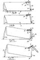
- the closed position of the side wall flap 4 is also in the simplified representation according to Fig. 2a to recognize.
- Fig. 2a-2d Furthermore, it can be seen that the side wall flap 4 is articulated on the pivot support arm protruding to the rear from the pivot axis 8 in such a way that, by pivoting the pivot support arm 6, it can lift (see the change between FIG Fig. 2a and 2b ), in which the locking counter-element 20 of the side wall flap 4 of the locking element 18 is released. If the pivoting process of the Schwenkhalterungsarme 6 stopped in this state of the side wall flap 4, the unlocked side wall flap 4 about the pendulum axis 22 (see. Fig. 2c ) oscillate when the tilting structure is tilted about the tilting axis 19, wherein the in Fig. 2c shown vertical position is strived for and possibly prevented by bulk material, which flows in the discharge area 14 of the tipper body 2.
- Fig. 3 a simplified hydraulic circuit diagram is shown, based on which the unlocking and pivoting operation of the side wall flap 4 will be explained in more detail below.
- Fig. 3 the double-acting hydraulic cylinder-piston units for the operation of the side wall flap 4 characterized. They are connected via hydraulic lines 30, 32 to a control valve block 34 for controlling the pressure fluid flow from the pump 36 to the cylinders 10 and for controlling the pressure fluid discharge from the cylinders 10 to a tank 60.
- the valve setting of the control valve block 34 by means of a (not shown) pneumatic adjusting device in accordance with the operation of an example provided in a cab of the dump truck operating device, such as a shift lever.
- a (not shown) pneumatic adjusting device in accordance with the operation of an example provided in a cab of the dump truck operating device, such as a shift lever.
- the single-acting Tilting cylinder 23 is connected via the hydraulic line 38 to the tilting valve block 40 for controlling the pressure fluid flow from the pump 42 to the tilting cylinder 23 and for controlling the return flow from the tilting cylinder 23 to the tank 60.
- a pressure transmission cylinder 46 is provided, the cylinder space is divided by a piston 48 into two cylinder chambers 50, 52.
- the connected to the hydraulic line 30 cylinder chamber 52 is penetrated by the piston rod 49 of the piston 48.
- the rodless cylinder chamber 50 is connected to the pressure fluid line 38.
- the pressure transfer cylinder 46 is a hydraulic transmission element, which comes into effect when the piston 48 performs a piston stroke when pressurized in the cylinder chamber 50. He transmits the high pressure to the hydraulic fluid line 30 and thus to the in Fig.
- the hydraulic auxiliary circuit comprises in the example, the pump 42, the branch line 44 with the pressure transfer cylinder 46 provided therein and a return path 70 to the tank, said return path includes a normally-off control valve 72 which is controlled by the pressure in the line 30, such that at Pressure supply to the cylinder chambers 54 of the cylinder-piston units 10, the control valve 72 is switched to passage to the tank 60. It can then pass through the lines 32 and 70 displaced from the cylinder chambers 61 hydraulic fluid to the tank 60.
- the hydraulic fluid used is preferably oil.
- FIG. 4 shows a simplified hydraulic circuit diagram for a further embodiment of the invention. As far as in Fig. 4 functionally or objectively the same elements as in Fig. 3 are shown, these elements are in both FIGS. 3 and 4 each marked with the same reference numerals.
- the pressure transfer cylinder 46 is in Fig. 4 supplied by the pump 36, which is responsible for the pivoting operation of the cylinder-piston units 10. According to the embodiment Fig. 4 It is necessary that the pressure transfer cylinder 46 has the largest possible hydraulic translation to produce sufficiently large piston rod forces on the cylinder-piston units 10.
- control valve block 34 and the pump 36 are still a control valve 74 for controlling the pressure fluid flow from the pump 36 to the pressure transfer cylinder 46 and 46 provided by the pressure transfer cylinder back to the tank 60.
Landscapes
- Engineering & Computer Science (AREA)
- Transportation (AREA)
- Mechanical Engineering (AREA)
- Actuator (AREA)
- Fluid-Pressure Circuits (AREA)
- Vehicle Body Suspensions (AREA)
- Specific Conveyance Elements (AREA)
- Body Structure For Vehicles (AREA)
- Forklifts And Lifting Vehicles (AREA)
Claims (10)
- Dispositif basculant d'un véhicule à benne basculante, avec une structure basculante (2) et un dispositif d'entraînement basculant hydraulique (23) pour faire pivoter la structure basculante (2) autour d'un axe de basculement (19), dans lequel la structure basculante (2) présente un cadre (16) et, sur celui-ci, au moins un volet latéral (4), en particulier un volet arrière, pouvant pivoter autour d'un axe de pivotement (8) pour fermer et ouvrir une zone de versement (14) de la structure basculante (2), ainsi qu'un dispositif de verrouillage (18, 20) verrouillant le volet latéral (4) dans sa position de fermeture, dans lequel au moins une unité à piston et cylindre hydraulique (10) est prévue comme dispositif d'entraînement pivotant pour le volet latéral, unité au moyen de laquelle le dispositif de verrouillage (18, 20) peut également être actionné pour libérer le volet latéral (4) de son verrouillage, dans lequel l'unité à piston et cylindre (10) peut être sollicitée, par l'intermédiaire d'un système (34) de vanne de commande, avec une pression provenant d'un circuit hydraulique principal associé à l'actionnement de volet latéral, afin de produire une course de piston de l'unité à piston et cylindre (10) qui déclenche le mouvement d'ouverture du volet de latéral (4),
caractérisé en ce que l'unité à piston et cylindre (10) peut être sollicitée, sur une zone limitée de sa course de piston correspondant au moins à l'opération de déverrouillage de son dispositif de verrouillage (18, 20), avec une pression accrue depuis un circuit hydraulique auxiliaire ou une branche auxiliaire (44). - Dispositif basculant selon la revendication 1, caractérisé par des moyens de commande qui sont agencés pour, à lamorce du basculement de la structure basculante depuis la position de base de déplacement, activer automatiquement le circuit auxiliaire hydraulique ou la branche auxiliaire (44) pour solliciter l'unité à piston et cylindre (10).
- Dispositif basculant selon la revendication 1 ou 2, caractérisé en ce que le dispositif de verrouillage (18, 20) présente au moins un élément de verrouillage (18) fixé sur le cadre (16) de la structure basculante au voisinage de la zone de déversement (14), élément qui saisit par l'arrière avec effet de verrouillage un contre-élément de verrouillage (20) du volet latéral (4) dans sa position de fermeture, le verrouillage pouvant être levé en soulevant le volet latéral (4), et en ce que le volet latéral (4) est accroché à un système de support pivotant (6) au voisinage de son extrémité supérieure dans la position de fermeture, le système de support pivotant (6) pouvant pivoter autour de l'axe de pivotement (8) depuis une position correspondant à la position de fermeture du volet latéral (4) au moyen de l'unité à piston et cylindre (10), afin de déverrouiller le volet latéral (4) depuis sa position de fermeture par soulèvement et de le faire pivoter jusqu'à une position d'ouverture.
- Dispositif basculant selon la revendication 3, caractérisé en ce que l'unité à piston et cylindre (10) peut être commandée dans un mode de déverrouillage de telle manière qu'elle n'exécute pour l'essentiel que la course limitée de piston nécessaire au déverrouillage du volet latéral (4), et en ce que le volet latéral (4) ainsi déverrouillé peut aller et venir sur le système de support pivotant (6) autour d'un axe parallèle à l'axe de basculement (19) quand la structure pivotante (2) est pivotée jusqu'à une position de basculement soulevée.
- Dispositif basculant selon l'une des revendications précédentes, caractérisé en ce que le circuit auxiliaire hydraulique ou la branche auxiliaire (44) est raccordé(e) au côté pression d'une pompe (42) pour l'alimentation hydraulique du dispositif d'entraînement basculant (23).
- Dispositif basculant selon l'une des revendications précédentes, caractérisé en ce que le circuit auxiliaire hydraulique ou la branche auxiliaire (44) et le circuit hydraulique principal sont alimentés en fluide sous pression depuis des pompes (36, 42) différentes.
- Dispositif basculant selon l'une des revendications 1 à 5, caractérisé en ce que le circuit auxiliaire hydraulique ou la branche auxiliaire et le circuit hydraulique principal sont alimentés en fluide sous pression depuis la même pompe (36, fig. 4).
- Dispositif basculant selon l'une des revendications précédentes, caractérisé en ce que le circuit auxiliaire hydraulique ou la branche auxiliaire (44) contient un cylindre de transfert de pression (46), en particulier à amplification hydraulique.
- Dispositif basculant selon la revendication 8, caractérisé en ce que le cylindre de transfert de pression (46) est subdivisé intérieurement en deux chambres de cylindre (50, 52) par un piston (48) présentant d'un côté une tige de piston (49), la chambre de cylindre (52) traversée par la tige de piston (49) communiquant hydrauliquement avec l'unité à piston et cylindre (10) pour le déverrouillage et pour l'entraînement pivotant du volet latéral (4), tandis que l'autre chambre de cylindre (50) est raccordée éventuellement par l'intermédiaire d'un système de vanne à une pompe (42) envoyant un fluide sous pression, et le cylindre de transfert de pression (46) étant dimensionné en sorte que la quantité de fluide sous pression acheminée lors d'une course maximale complète de son piston (48) en direction de l'unité à piston et cylindre (10) est suffisante pour provoquer, au niveau de l'unité à piston et cylindre (10), une course de piston limitée essentiellement à l'opération de déverrouillage du dispositif de déverrouillage (18, 20).
- Dispositif basculant selon la revendication 9, caractérisé en ce que le cylindre de transfert de pression (46) est monté stationnaire sur une partie de châssis de véhicule, de telle manière qu'il peut être sollicitée mécaniquement par la structure basculante (2) afin de faire passer la tige de piston (49) dans la position de base rentrée dans le cylindre de transfert de pression quand la structure basculante (2) passe d'une position de basculement soulevée à la position de base pour le déplacement du véhicule.
Applications Claiming Priority (2)
| Application Number | Priority Date | Filing Date | Title |
|---|---|---|---|
| DE10348605A DE10348605A1 (de) | 2003-10-20 | 2003-10-20 | Kippvorrichtung eines Kipperfahrzeugs |
| DE10348605 | 2003-10-20 |
Publications (2)
| Publication Number | Publication Date |
|---|---|
| EP1526036A1 EP1526036A1 (fr) | 2005-04-27 |
| EP1526036B1 true EP1526036B1 (fr) | 2009-04-08 |
Family
ID=34384377
Family Applications (1)
| Application Number | Title | Priority Date | Filing Date |
|---|---|---|---|
| EP04022566A Expired - Lifetime EP1526036B1 (fr) | 2003-10-20 | 2004-09-22 | Dispositif de basculation pour un camion-benne |
Country Status (3)
| Country | Link |
|---|---|
| EP (1) | EP1526036B1 (fr) |
| AT (1) | ATE427856T1 (fr) |
| DE (2) | DE10348605A1 (fr) |
Cited By (1)
| Publication number | Priority date | Publication date | Assignee | Title |
|---|---|---|---|---|
| DE202015105380U1 (de) | 2015-10-12 | 2017-01-13 | Ulrich Humbaur | Riegeleinrichtung für Pendelbordwand |
Families Citing this family (4)
| Publication number | Priority date | Publication date | Assignee | Title |
|---|---|---|---|---|
| CN100497041C (zh) * | 2006-07-24 | 2009-06-10 | 赵永胜 | 具有自动液控尾挡板的自卸车 |
| DE202011052015U1 (de) | 2011-11-18 | 2013-03-20 | Kögel Trailer GmbH & Co. KG | Fahrzeugaufbau |
| CN106965738B (zh) * | 2017-04-28 | 2024-03-19 | 山东嵘野房车制造服务有限公司 | 一种前后双翻式牵引式房车 |
| DE102017221065A1 (de) * | 2017-11-24 | 2019-05-29 | Franz Xaver Meiller Fahrzeug- Und Maschinenfabrik - Gmbh & Co Kg | Bordwandvorrichtung eines Lastentransportbehälters eines Lastentransportfahrzeugs |
Family Cites Families (5)
| Publication number | Priority date | Publication date | Assignee | Title |
|---|---|---|---|---|
| US4307541A (en) * | 1979-11-30 | 1981-12-29 | Dempster Systems Inc. | Tail-gate operating and locking mechanism |
| DE4417766A1 (de) * | 1994-05-20 | 1995-11-23 | Gerhard Spaegele | Heckbordwand für Kipperfahrzeuge |
| DE29507084U1 (de) * | 1995-04-27 | 1995-06-29 | Maschinenbau Otto Gruber Ges.M.B.H., Saalfelden | Hydraulisch betätigbare Rückwand |
| DE19940811A1 (de) * | 1999-08-27 | 2001-03-08 | Meiller Fahrzeuge | Bordwandeinrichtung mit einer Bordwandklappe für einen Transportbehälteraufbau, insbesondere Kippbrücke, eines Lastentransportfahrzeugs |
| US6572197B1 (en) * | 2001-05-11 | 2003-06-03 | Joel E. Clough | Vehicle latch assembly |
-
2003
- 2003-10-20 DE DE10348605A patent/DE10348605A1/de not_active Withdrawn
-
2004
- 2004-09-22 DE DE502004009301T patent/DE502004009301D1/de not_active Expired - Lifetime
- 2004-09-22 EP EP04022566A patent/EP1526036B1/fr not_active Expired - Lifetime
- 2004-09-22 AT AT04022566T patent/ATE427856T1/de active
Cited By (1)
| Publication number | Priority date | Publication date | Assignee | Title |
|---|---|---|---|---|
| DE202015105380U1 (de) | 2015-10-12 | 2017-01-13 | Ulrich Humbaur | Riegeleinrichtung für Pendelbordwand |
Also Published As
| Publication number | Publication date |
|---|---|
| ATE427856T1 (de) | 2009-04-15 |
| EP1526036A1 (fr) | 2005-04-27 |
| DE10348605A1 (de) | 2005-06-30 |
| DE502004009301D1 (de) | 2009-05-20 |
Similar Documents
| Publication | Publication Date | Title |
|---|---|---|
| DE69307952T2 (de) | Hub-Kippvorrichtung zum Heben und Kippen eines Müllbehälters | |
| AT399130B (de) | Anordnung zur hydraulischen betätigung eines fahrzeugverdeckes | |
| EP0959216B1 (fr) | Ensemble pour l'actionnement hydraulique d'un hayon arrière | |
| EP0959217B1 (fr) | Ensemble pour l'actionnement hydraulique d'un hayon arrière | |
| EP0490366B1 (fr) | Véhicule de transport avec conteneur interchangeable | |
| DE2066194C2 (fr) | ||
| EP2799283B1 (fr) | Véhicule de transport de charge doté d'un conteneur interchangeable et d'un appareil de levage pour un conteneur interchangeable | |
| EP1526036B1 (fr) | Dispositif de basculation pour un camion-benne | |
| EP1600643A1 (fr) | Dispositif de commande pour un système de manutention hydraulique, en particulier un bras pivotant d'un système de levage de benne amovible de camion | |
| EP2918445B1 (fr) | Multibenne | |
| EP1702792B1 (fr) | Système de levage de benne amovible de camion | |
| DE10063610B4 (de) | Steuereinrichtung zur Steuerung einer hydraulischen Schwenkantriebsvorrichtung | |
| EP0732256A2 (fr) | Dispositif pour basculer la cabine de conducteur d'un véhicule utilitaire | |
| DE6602897U (de) | Lastenheber oder klammer mit verzoegerungsvorrichtung fuer klemmarme. | |
| DE102006024731B3 (de) | Verfahren zur lagegerechten Ausrichtung einer an einem heb- und senkbaren Hubgerüst einer Arbeitsmaschine kippbar angeordeten Arbeitausrüstung sowie Arbeitsmaschine | |
| DE2200879A1 (de) | Einrichtung zum anheben von lasten | |
| AT404173B (de) | Rückschlagventil | |
| EP2639104A1 (fr) | Commande hydraulique d'un vérin de basculement facilement actionnable | |
| DE69205229T2 (de) | Einrichtung zur Einstellung der Höhe eines Fahrzeuguntergestells. | |
| DE9317545U1 (de) | Schwenkbare Bordwand eines Transportfahrzeugs | |
| DE1270494B (de) | Schaufellader | |
| DE102005044897B4 (de) | Hydraulische Antriebs- und Steuerungsvorrichtung und Verfahren zum Betrieb derselben | |
| DE925445C (de) | Versenkbares Verdeck, vorzugsweise fuer Kraftfahrzeuge | |
| DE102007015820A1 (de) | Hydraulisch betätigte Ladebordwand | |
| DE19914409A1 (de) | Überkopflader-Fahrzeug |
Legal Events
| Date | Code | Title | Description |
|---|---|---|---|
| PUAI | Public reference made under article 153(3) epc to a published international application that has entered the european phase |
Free format text: ORIGINAL CODE: 0009012 |
|
| AK | Designated contracting states |
Kind code of ref document: A1 Designated state(s): AT BE BG CH CY CZ DE DK EE ES FI FR GB GR HU IE IT LI LU MC NL PL PT RO SE SI SK TR |
|
| AX | Request for extension of the european patent |
Extension state: AL HR LT LV MK |
|
| 17P | Request for examination filed |
Effective date: 20050926 |
|
| AKX | Designation fees paid |
Designated state(s): AT BE BG CH CY CZ DE DK EE ES FI FR GB GR HU IE IT LI LU MC NL PL PT RO SE SI SK TR |
|
| AXX | Extension fees paid |
Extension state: HR Payment date: 20050926 Extension state: LV Payment date: 20050926 Extension state: MK Payment date: 20050926 Extension state: LT Payment date: 20050926 |
|
| GRAP | Despatch of communication of intention to grant a patent |
Free format text: ORIGINAL CODE: EPIDOSNIGR1 |
|
| GRAS | Grant fee paid |
Free format text: ORIGINAL CODE: EPIDOSNIGR3 |
|
| GRAA | (expected) grant |
Free format text: ORIGINAL CODE: 0009210 |
|
| AK | Designated contracting states |
Kind code of ref document: B1 Designated state(s): AT BE BG CH CY CZ DE DK EE ES FI FR GB GR HU IE IT LI LU MC NL PL PT RO SE SI SK TR |
|
| AX | Request for extension of the european patent |
Extension state: HR LT LV MK |
|
| REG | Reference to a national code |
Ref country code: GB Ref legal event code: FG4D Free format text: NOT ENGLISH |
|
| REG | Reference to a national code |
Ref country code: CH Ref legal event code: EP |
|
| REG | Reference to a national code |
Ref country code: IE Ref legal event code: FG4D |
|
| REF | Corresponds to: |
Ref document number: 502004009301 Country of ref document: DE Date of ref document: 20090520 Kind code of ref document: P |
|
| PG25 | Lapsed in a contracting state [announced via postgrant information from national office to epo] |
Ref country code: SI Free format text: LAPSE BECAUSE OF FAILURE TO SUBMIT A TRANSLATION OF THE DESCRIPTION OR TO PAY THE FEE WITHIN THE PRESCRIBED TIME-LIMIT Effective date: 20090408 |
|
| LTIE | Lt: invalidation of european patent or patent extension |
Effective date: 20090408 |
|
| REG | Reference to a national code |
Ref country code: IE Ref legal event code: FD4D |
|
| PG25 | Lapsed in a contracting state [announced via postgrant information from national office to epo] |
Ref country code: PT Free format text: LAPSE BECAUSE OF FAILURE TO SUBMIT A TRANSLATION OF THE DESCRIPTION OR TO PAY THE FEE WITHIN THE PRESCRIBED TIME-LIMIT Effective date: 20090908 Ref country code: FI Free format text: LAPSE BECAUSE OF FAILURE TO SUBMIT A TRANSLATION OF THE DESCRIPTION OR TO PAY THE FEE WITHIN THE PRESCRIBED TIME-LIMIT Effective date: 20090408 Ref country code: ES Free format text: LAPSE BECAUSE OF FAILURE TO SUBMIT A TRANSLATION OF THE DESCRIPTION OR TO PAY THE FEE WITHIN THE PRESCRIBED TIME-LIMIT Effective date: 20090719 |
|
| PG25 | Lapsed in a contracting state [announced via postgrant information from national office to epo] |
Ref country code: PL Free format text: LAPSE BECAUSE OF FAILURE TO SUBMIT A TRANSLATION OF THE DESCRIPTION OR TO PAY THE FEE WITHIN THE PRESCRIBED TIME-LIMIT Effective date: 20090408 Ref country code: SE Free format text: LAPSE BECAUSE OF FAILURE TO SUBMIT A TRANSLATION OF THE DESCRIPTION OR TO PAY THE FEE WITHIN THE PRESCRIBED TIME-LIMIT Effective date: 20090708 |
|
| PG25 | Lapsed in a contracting state [announced via postgrant information from national office to epo] |
Ref country code: EE Free format text: LAPSE BECAUSE OF FAILURE TO SUBMIT A TRANSLATION OF THE DESCRIPTION OR TO PAY THE FEE WITHIN THE PRESCRIBED TIME-LIMIT Effective date: 20090408 Ref country code: DK Free format text: LAPSE BECAUSE OF FAILURE TO SUBMIT A TRANSLATION OF THE DESCRIPTION OR TO PAY THE FEE WITHIN THE PRESCRIBED TIME-LIMIT Effective date: 20090408 Ref country code: RO Free format text: LAPSE BECAUSE OF FAILURE TO SUBMIT A TRANSLATION OF THE DESCRIPTION OR TO PAY THE FEE WITHIN THE PRESCRIBED TIME-LIMIT Effective date: 20090408 Ref country code: IE Free format text: LAPSE BECAUSE OF FAILURE TO SUBMIT A TRANSLATION OF THE DESCRIPTION OR TO PAY THE FEE WITHIN THE PRESCRIBED TIME-LIMIT Effective date: 20090408 Ref country code: CZ Free format text: LAPSE BECAUSE OF FAILURE TO SUBMIT A TRANSLATION OF THE DESCRIPTION OR TO PAY THE FEE WITHIN THE PRESCRIBED TIME-LIMIT Effective date: 20090408 |
|
| PLBE | No opposition filed within time limit |
Free format text: ORIGINAL CODE: 0009261 |
|
| STAA | Information on the status of an ep patent application or granted ep patent |
Free format text: STATUS: NO OPPOSITION FILED WITHIN TIME LIMIT |
|
| PG25 | Lapsed in a contracting state [announced via postgrant information from national office to epo] |
Ref country code: SK Free format text: LAPSE BECAUSE OF FAILURE TO SUBMIT A TRANSLATION OF THE DESCRIPTION OR TO PAY THE FEE WITHIN THE PRESCRIBED TIME-LIMIT Effective date: 20090408 |
|
| 26N | No opposition filed |
Effective date: 20100111 |
|
| BERE | Be: lapsed |
Owner name: FRANZ XAVER MEILLER FAHRZEUG- UND MASCHINENFABRIK Effective date: 20090930 |
|
| PG25 | Lapsed in a contracting state [announced via postgrant information from national office to epo] |
Ref country code: BG Free format text: LAPSE BECAUSE OF FAILURE TO SUBMIT A TRANSLATION OF THE DESCRIPTION OR TO PAY THE FEE WITHIN THE PRESCRIBED TIME-LIMIT Effective date: 20090708 |
|
| PG25 | Lapsed in a contracting state [announced via postgrant information from national office to epo] |
Ref country code: MC Free format text: LAPSE BECAUSE OF NON-PAYMENT OF DUE FEES Effective date: 20090930 |
|
| REG | Reference to a national code |
Ref country code: CH Ref legal event code: PL |
|
| GBPC | Gb: european patent ceased through non-payment of renewal fee |
Effective date: 20090922 |
|
| PG25 | Lapsed in a contracting state [announced via postgrant information from national office to epo] |
Ref country code: BE Free format text: LAPSE BECAUSE OF NON-PAYMENT OF DUE FEES Effective date: 20090930 |
|
| PG25 | Lapsed in a contracting state [announced via postgrant information from national office to epo] |
Ref country code: GR Free format text: LAPSE BECAUSE OF FAILURE TO SUBMIT A TRANSLATION OF THE DESCRIPTION OR TO PAY THE FEE WITHIN THE PRESCRIBED TIME-LIMIT Effective date: 20090709 Ref country code: CH Free format text: LAPSE BECAUSE OF NON-PAYMENT OF DUE FEES Effective date: 20090930 Ref country code: LI Free format text: LAPSE BECAUSE OF NON-PAYMENT OF DUE FEES Effective date: 20090930 |
|
| PG25 | Lapsed in a contracting state [announced via postgrant information from national office to epo] |
Ref country code: GB Free format text: LAPSE BECAUSE OF NON-PAYMENT OF DUE FEES Effective date: 20090922 |
|
| PG25 | Lapsed in a contracting state [announced via postgrant information from national office to epo] |
Ref country code: IT Free format text: LAPSE BECAUSE OF FAILURE TO SUBMIT A TRANSLATION OF THE DESCRIPTION OR TO PAY THE FEE WITHIN THE PRESCRIBED TIME-LIMIT Effective date: 20090408 |
|
| PG25 | Lapsed in a contracting state [announced via postgrant information from national office to epo] |
Ref country code: LU Free format text: LAPSE BECAUSE OF NON-PAYMENT OF DUE FEES Effective date: 20090922 |
|
| PG25 | Lapsed in a contracting state [announced via postgrant information from national office to epo] |
Ref country code: HU Free format text: LAPSE BECAUSE OF FAILURE TO SUBMIT A TRANSLATION OF THE DESCRIPTION OR TO PAY THE FEE WITHIN THE PRESCRIBED TIME-LIMIT Effective date: 20091009 |
|
| PG25 | Lapsed in a contracting state [announced via postgrant information from national office to epo] |
Ref country code: TR Free format text: LAPSE BECAUSE OF FAILURE TO SUBMIT A TRANSLATION OF THE DESCRIPTION OR TO PAY THE FEE WITHIN THE PRESCRIBED TIME-LIMIT Effective date: 20090408 |
|
| PG25 | Lapsed in a contracting state [announced via postgrant information from national office to epo] |
Ref country code: CY Free format text: LAPSE BECAUSE OF FAILURE TO SUBMIT A TRANSLATION OF THE DESCRIPTION OR TO PAY THE FEE WITHIN THE PRESCRIBED TIME-LIMIT Effective date: 20090408 |
|
| REG | Reference to a national code |
Ref country code: FR Ref legal event code: PLFP Year of fee payment: 13 |
|
| PGFP | Annual fee paid to national office [announced via postgrant information from national office to epo] |
Ref country code: NL Payment date: 20160920 Year of fee payment: 13 |
|
| REG | Reference to a national code |
Ref country code: FR Ref legal event code: PLFP Year of fee payment: 14 |
|
| REG | Reference to a national code |
Ref country code: NL Ref legal event code: MM Effective date: 20171001 |
|
| PG25 | Lapsed in a contracting state [announced via postgrant information from national office to epo] |
Ref country code: NL Free format text: LAPSE BECAUSE OF NON-PAYMENT OF DUE FEES Effective date: 20171001 |
|
| REG | Reference to a national code |
Ref country code: FR Ref legal event code: PLFP Year of fee payment: 15 |
|
| PGFP | Annual fee paid to national office [announced via postgrant information from national office to epo] |
Ref country code: AT Payment date: 20190919 Year of fee payment: 16 |
|
| PGFP | Annual fee paid to national office [announced via postgrant information from national office to epo] |
Ref country code: DE Payment date: 20200731 Year of fee payment: 17 Ref country code: FR Payment date: 20200914 Year of fee payment: 17 |
|
| REG | Reference to a national code |
Ref country code: AT Ref legal event code: MM01 Ref document number: 427856 Country of ref document: AT Kind code of ref document: T Effective date: 20200922 |
|
| PG25 | Lapsed in a contracting state [announced via postgrant information from national office to epo] |
Ref country code: AT Free format text: LAPSE BECAUSE OF NON-PAYMENT OF DUE FEES Effective date: 20200922 |
|
| REG | Reference to a national code |
Ref country code: DE Ref legal event code: R119 Ref document number: 502004009301 Country of ref document: DE |
|
| PG25 | Lapsed in a contracting state [announced via postgrant information from national office to epo] |
Ref country code: FR Free format text: LAPSE BECAUSE OF NON-PAYMENT OF DUE FEES Effective date: 20210930 Ref country code: DE Free format text: LAPSE BECAUSE OF NON-PAYMENT OF DUE FEES Effective date: 20220401 |