EP1526040B1 - Un element de fixation pour le raccordement d'un élément structurel sur une partie de support - Google Patents
Un element de fixation pour le raccordement d'un élément structurel sur une partie de support Download PDFInfo
- Publication number
- EP1526040B1 EP1526040B1 EP04021180A EP04021180A EP1526040B1 EP 1526040 B1 EP1526040 B1 EP 1526040B1 EP 04021180 A EP04021180 A EP 04021180A EP 04021180 A EP04021180 A EP 04021180A EP 1526040 B1 EP1526040 B1 EP 1526040B1
- Authority
- EP
- European Patent Office
- Prior art keywords
- outer webs
- web
- fastener element
- locking
- holding portions
- Prior art date
- Legal status (The legal status is an assumption and is not a legal conclusion. Google has not performed a legal analysis and makes no representation as to the accuracy of the status listed.)
- Expired - Lifetime
Links
- 238000007789 sealing Methods 0.000 claims description 5
- 239000000463 material Substances 0.000 claims 2
- 239000002184 metal Substances 0.000 description 7
- 238000000034 method Methods 0.000 description 2
- 238000004080 punching Methods 0.000 description 2
- QNRATNLHPGXHMA-XZHTYLCXSA-N (r)-(6-ethoxyquinolin-4-yl)-[(2s,4s,5r)-5-ethyl-1-azabicyclo[2.2.2]octan-2-yl]methanol;hydrochloride Chemical compound Cl.C([C@H]([C@H](C1)CC)C2)CN1[C@@H]2[C@H](O)C1=CC=NC2=CC=C(OCC)C=C21 QNRATNLHPGXHMA-XZHTYLCXSA-N 0.000 description 1
- 230000009471 action Effects 0.000 description 1
- 238000005260 corrosion Methods 0.000 description 1
- 230000007797 corrosion Effects 0.000 description 1
- 238000001746 injection moulding Methods 0.000 description 1
- 238000003780 insertion Methods 0.000 description 1
- 230000037431 insertion Effects 0.000 description 1
- 238000009434 installation Methods 0.000 description 1
- 230000003993 interaction Effects 0.000 description 1
- 238000012423 maintenance Methods 0.000 description 1
- 230000008439 repair process Effects 0.000 description 1
- 230000000284 resting effect Effects 0.000 description 1
- 230000007704 transition Effects 0.000 description 1
Images

Classifications
-
- B—PERFORMING OPERATIONS; TRANSPORTING
- B60—VEHICLES IN GENERAL
- B60R—VEHICLES, VEHICLE FITTINGS, OR VEHICLE PARTS, NOT OTHERWISE PROVIDED FOR
- B60R13/00—Elements for body-finishing, identifying, or decorating; Arrangements or adaptations for advertising purposes
- B60R13/02—Internal Trim mouldings ; Internal Ledges; Wall liners for passenger compartments; Roof liners
- B60R13/0206—Arrangements of fasteners and clips specially adapted for attaching inner vehicle liners or mouldings
-
- F—MECHANICAL ENGINEERING; LIGHTING; HEATING; WEAPONS; BLASTING
- F16—ENGINEERING ELEMENTS AND UNITS; GENERAL MEASURES FOR PRODUCING AND MAINTAINING EFFECTIVE FUNCTIONING OF MACHINES OR INSTALLATIONS; THERMAL INSULATION IN GENERAL
- F16B—DEVICES FOR FASTENING OR SECURING CONSTRUCTIONAL ELEMENTS OR MACHINE PARTS TOGETHER, e.g. NAILS, BOLTS, CIRCLIPS, CLAMPS, CLIPS OR WEDGES; JOINTS OR JOINTING
- F16B21/00—Means for preventing relative axial movement of a pin, spigot, shaft or the like and a member surrounding it; Stud-and-socket releasable fastenings
- F16B21/06—Releasable fastening devices with snap-action
- F16B21/08—Releasable fastening devices with snap-action in which the stud, pin, or spigot has a resilient part
-
- F—MECHANICAL ENGINEERING; LIGHTING; HEATING; WEAPONS; BLASTING
- F16—ENGINEERING ELEMENTS AND UNITS; GENERAL MEASURES FOR PRODUCING AND MAINTAINING EFFECTIVE FUNCTIONING OF MACHINES OR INSTALLATIONS; THERMAL INSULATION IN GENERAL
- F16B—DEVICES FOR FASTENING OR SECURING CONSTRUCTIONAL ELEMENTS OR MACHINE PARTS TOGETHER, e.g. NAILS, BOLTS, CIRCLIPS, CLAMPS, CLIPS OR WEDGES; JOINTS OR JOINTING
- F16B5/00—Joining sheets or plates, e.g. panels, to one another or to strips or bars parallel to them
- F16B5/06—Joining sheets or plates, e.g. panels, to one another or to strips or bars parallel to them by means of clamps or clips
- F16B5/0607—Joining sheets or plates, e.g. panels, to one another or to strips or bars parallel to them by means of clamps or clips joining sheets or plates to each other
- F16B5/0621—Joining sheets or plates, e.g. panels, to one another or to strips or bars parallel to them by means of clamps or clips joining sheets or plates to each other in parallel relationship
- F16B5/065—Joining sheets or plates, e.g. panels, to one another or to strips or bars parallel to them by means of clamps or clips joining sheets or plates to each other in parallel relationship the plates being one on top of the other and distanced from each other, e.g. by using protrusions to keep contact and distance
-
- Y—GENERAL TAGGING OF NEW TECHNOLOGICAL DEVELOPMENTS; GENERAL TAGGING OF CROSS-SECTIONAL TECHNOLOGIES SPANNING OVER SEVERAL SECTIONS OF THE IPC; TECHNICAL SUBJECTS COVERED BY FORMER USPC CROSS-REFERENCE ART COLLECTIONS [XRACs] AND DIGESTS
- Y10—TECHNICAL SUBJECTS COVERED BY FORMER USPC
- Y10T—TECHNICAL SUBJECTS COVERED BY FORMER US CLASSIFICATION
- Y10T24/00—Buckles, buttons, clasps, etc.
- Y10T24/30—Trim molding fastener
- Y10T24/309—Plastic type
Definitions
- the invention relates to a fastener element for connecting a structural part, in particular a lining, to a support part having a fastening hole, in particular a body sheet of an automobile, according to the preamble of claim 1.
- a multiplicity of so-called clips or fastener elements have become known for the fastening of linings and other attachments to the automobile body.
- the fastener elements which normally are manufactured from a plastic, have a head for connection to the part to be fastened and a base or shank which is forced into or lockingly inserted into an aperture of the body.
- the aperture or hole in the body may be of various shapes, e.g. that of a rectangle, elongated hole, circular hole or molded hole.
- fastener elements employed at such points require to be disassembled and reassembled. If possible, the assembly and disassembly forces, even if the elements are repeatedly used, should not depart substantially from the values encountered during their first use.
- Installation apertures have sharp edges in most cases and can also present a burr left from punching so that some part of the outer contour of the fastener element is abraded during every assembly and disassembly procedure. This causes the holding forces to weaken and the fastener element to fail, in an extreme case, when the number of assembly cycles increases.
- EP 0 954 459 B1 has made known a fastener element for which the problem described is resolved by clipping a two-legged metallic spring onto the shank of a plastic body such that the legs face their free ends slightly outwardly towards the head of the fastener element when the spring is in a stress-relieved state.
- the free ends of the spring legs grip behind the hole border.
- a shoulder may be formed in the spring legs which grips behind the hole border.
- the fastener body exhibits two approximately parallel spaced outer webs which are connected by a transverse web at a spacing from the free end of the outer webs.
- the transverse web stabilizes the outer webs and has a further function reference to which will be made farther below.
- the transverse web is tapered towards its lower end.
- the outer webs On the sides facing each other close to the free end, the outer webs have projections with lower and upper ramp surfaces. The lower ramp surfaces converge towards the free end of the outer webs and the upper ramp surfaces converge towards the head.
- the washer-like locking part which can be of an approximately rectangular shape and has a measure which is larger than the diameter of the fasting hole in any case, has an approximately rectangular aperture or opening.
- Two opposed sides of the aperture have pivotically formed thereto holding portions each which are approximately L-shaped in the cross-section.
- Each holding portion has a first web portion formed to the locking part and a second web portion which extends from the upper side of the locking portion to the lower side of the locking portion through the aperture.
- the dimensions of the aperture and holding portions are such that a slot is formed each between the respective other opposed sides of the aperture and the two holding portions, into which an outer web can be fittingly inserted from the upper side of the locking part in such a way that the lower ramp surfaces of the projections pivot the holding portions away from each other and the lower sides of the second web portions can come to lie on the upper ramp surfaces.
- the outer webs are introduced into the slots of the locking part by a certain amount. This helps obtain a pre-assembly position of the parts relative to each other. Shoulders on the outsides of the outer webs can grip under the washer-like locking part at the lower side and secure the locking part against removal from the outer webs of the fastener body.
- the lower end of the transverse web is approximately triangular in cross-section parallel to the outer webs to make it easier to pivot the holding portions as described. There is a spacing which facilitates the engagement of the transverse web between the holding portion in a stress-relieved state. Moreover, a rounded portion may be provided at the outer transition from the first web portion to the second one.
- another aspect of the invention provides that the surfaces facing each other of the first web portions of the holding portions include at least one locking portion the outside of the transverse web facing them is provided with at least a second locking portion cooperating with the first locking portion. It is preferred to provide two locking teeth or locking gaps spaced in an axial direction where different sheet thicknesses of the support part may be employed.
- the locking teeth or locking grooves are such as to allow the transverse web to be introduced relatively easily in between the opposed holding portions whereas relatively large holding forces are produced in the opposite direction.
- the inventive fastener element has a number of advantages. There is no wear during the assembly and disassembly. Assembly and disassembly forces are substantially constant.
- the inventive fastener element allows to precisely harmonize the holding and assembly forces. It is ready possible to mount it in fastening holes even if burr left from punching has remained therein. Furthermore, a relative large tolerance is possible with regard to the size of the fastening hole and the thickness of the support part.
- the inventive fastener element can be manufactured in a low-expenditure injection molding process. Its use for different hole shapes is also possible.
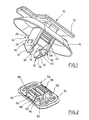
- the fastener body 10 shown in Fig. 1 has an elongate head 12 and a shank generally designated 14 which is connected to the head 12 and has two parallel spaced outer webs 18, 20 below an oval, conical sealing flange 16.
- the outer webs 18, 20 are elongated rectangular in cross-section with the longer sides of the outer webs 18, 20 extending parallel to each other.
- the outer webs 18, 20 have tapering introduction portions 22, 24 at the free end.
- the outer webs 18, 20 On the outer surfaces facing away from each other, the outer webs 18, 20 have elevations one of which is shown at 26.
- the elevations define a shoulder 28 facing head 12, reference to which will be made farther below.
- the outer webs have projections 30, 32 on the inner surfaces facing each other.
- the projections 30, 32 have lower ramp surfaces 34, 36 which converge downwardly towards the free end of the outer webs 18, 20 and upper ramp surfaces 38, 40 which converge towards the head 12.
- the contour of the projections 30, 32 is rhombic, for example.
- transverse web 42 which is triangular in section at the free end at 44 and has locking recesses 46 at opposite outer surfaces is extended between the outer webs 18, 20.
- the transverse web 42 stabilizes the outer webs 18, 20, but has more functions reference to which will be made farther below.
- the outer webs 18, 20 have ramp-like elevations, one of which is depicted at 48 in Fig. 1, on the sides facing each other.
- the elevations 48 extending transversely to the longitudinal axis of the outer webs 18, 20 slope down gradually towards the two ends as is clearly apparent from the perspective view of Fig. 1.
- a washer-like locking part 50 which approximately has a rectangular contour with rounded corners.
- the washer-like locking part 50 has a rectangular aperture 52.
- Holding portions 54, 56 extend from two opposed sides of the aperture 52.
- Each holding portion 54, 56 has a first web portion 58 which is joined to the locking part via a film hinge 60.
- the rectangular holding portions 54, 56 which are L-shaped in cross-section have a second web portion 62. While the first web portion 58 extends towards the aperture centre approximately in parallel, but outside the plane of the aperture 52 the second web portion 62 extends downwards to the lower side of the locking part 50 from the upper side of the locking part 50 that is recognizable in Fig. 2 through the aperture 52.
- the side of the first web portion 58 that faces upwards in Fig. 2 has two parallel locking teeth 64, 66.
- Slots 68, 70 which are delimited by the surfaces facing each other of the holding portions 54, 56 are formed between the other opposed sides of the aperture 52.
- the dimensions of the slots 68, 70 are such as to allow the outer webs 18, 20 of the fastener body 10 of Fig. 1 to be introduced and accommodated approximately fittingly therein.
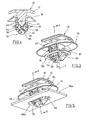
- a metal sheet is outlined at 58a, which has an oval fastening hole 60a.
- the metal sheet 58a is a support part and forms part of an automobile body, for example.
- Figs. 5 and 6 show how the fastener element 10 is introduced into the fastening hole 60a to an extent that the border of the locking part 50 rests on the metal sheet side facing it. Now, when a downward pressure is applied to the head 12 of the fastener body 10 in the position of Figs.
- the outer webs 18, 20 will be farther introduced into the fastening hole 60a and the triangular portion 44 of the transverse web 42 gets into engagement with the side facing it and the sides facing each other of the holding portions 54, 56 while continuing to pivot them farther by approximately further 45°, which now causes the second web portion 62 to grip under the lower side of the metal sheet 58a.
- the first web portions 58 define a triangular introduction opening for the transverse web 42.
- the first locking tooth 66 of the holding portions 54, 56 now interengages with the first locking groove 46 or locking gap of the transverse web 42 as can be seen well in Fig. 8. In this way, the fastener element 10 obtains an interlocking in the metal sheet 58a.
- the sealing flange 16 still has a spacing from the side facing it of the metal sheet 58a in the position of Figs. 7 and 8.
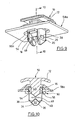
- the fastener body 10 can be forced in even farther as can be recognized in Figs. 9 and 10.
- the transverse web 42 continues to move in between the first web portions 58 of the holding portions 54, 56, which causes the second locking tooth 64 of the holding portions 54, 56 to engage the second locking groove 46 of the transverse web 42.
- two locking teeth 64, 66 and two grooves 46 are in engagement with each other on opposed sides each and cause a large holding force of the fastener element shown with the sealing flange now sealingly resting on the metal sheet 58a.
- Disassembly may be effected by pulling upwards on the fastener body 10, which causes the holding portions 54, 56 to be pivoted back to a position as is shown in Figs. 4 to 5. In this position, the second web portions 62 release the fastening hole 60a, enabling the fastener body 10, along with the locking part 50, to be readily removed from the fastening hole 60a. Re-assembly is performed in the way described above.
Landscapes
- Engineering & Computer Science (AREA)
- Mechanical Engineering (AREA)
- General Engineering & Computer Science (AREA)
- Insertion Pins And Rivets (AREA)
- Connection Of Plates (AREA)
Claims (8)
- Élément de fixation pour relier une pièce de structure, en particulier une garniture, à une pièce support ayant un trou d'attache, en particulier une tôle de carrosserie (58a) d'une automobile, comprenant un corps d'attache (10) formé d'une seule pièce en matière plastique - le corps d'attache (10) ayant une tête (12) pour la fixation de la pièce de structure, une tige (14) reliée à la tête (12) et une bride de fermeture (16) entre la tête (12) et la tige (14) - et une pièce de blocage (50) adaptée pour être reliée à la tige (14) par une liaison à ergot déblocable et ayant des parties en ergot qui travaillent avec un bord du trou d'attache quand on introduit la tige (14) dans le trou d'attache afin de fixer solidement l'élément de fixation sur la pièce support,
caractérisé en ce que :- la tige (14) a deux toiles extérieures (18, 20) espacées et sensiblement parallèles qui sont reliées entre elles par une toile transversale (42), ladite toile transversale (42) étant à distance de l'extrémité libre des toiles extérieures (18, 20) et ayant une partie conique (22, 24) diminuant progressivement vers l'extrémité inférieure de celle-ci, les toiles extérieures (18, 20) ayant sur leurs surfaces en vis-à-vis des saillies (30, 32) tout près de l'extrémité libre des toiles extérieures et comprenant des surfaces en rampe supérieures et inférieures, avec les surfaces en rampe inférieures (34, 36) qui convergent vers l'extrémité libre des toiles extérieures (18, 20) et les surfaces en rampe supérieures (38, 40) qui convergent vers la tête (12) ;- la pièce de blocage du genre rondelle (50) est faite en matière plastique et présente une ouverture sensiblement rectangulaire (52), des parties de retenue (54, 56) ayant en coupe transversale une forme sensiblement en L et reliées chacune à des bords opposés de l'ouverture (52), lesdites parties de retenue (54, 56) ayant une première partie de toile (58) qui est rattachée à la pièce de blocage du genre rondelle (50) et une seconde partie de toile (62) qui s'étend à partir de la face supérieure de la pièce de blocage dans l'ouverture (52) vers la face inférieure de la pièce de blocage (50);- une fente (68, 70) est pratiquée entre les autres bords opposés de l'ouverture (52) et les deux parties de retenue (54, 56), chacune apte à recevoir une toile extérieure (18) qui est à peu près assortie à la fente et est introduite à partir de la face supérieure de la pièce de blocage ;- les surfaces en rampe inférieures (34, 36) des saillies (30, 32) éloignent l'une de l'autre les parties de retenue (54, 56) et la face inférieure des secondes parties de toile (62) peut s'enclencher d'en haut avec les surfaces en rampe supérieures (38, 40) ;- l'extrémité inférieure de la toile transversale (42) et les surfaces en vis-à-vis associées des premières parties de toile (58) des parties de retenue (54, 56) sont formées de telle façon que les parties de retenue (54, 56) pivotent pour s'éloigner encore plus l'une de l'autre et les secondes parties de toile (62) saisissent par en dessous le bord du trou d'attache (60) si on introduit la tige (14) dans le trou d'attache (60) alors que la pièce de blocage du genre rondelle (50) s'enclenche avec la pièce support (58). - Élément de fixation selon la revendication 1, dans lequel l'extrémité inférieure de la toile transversale (42) a une section transversale parallèle aux toiles extérieures (18, 20) à peu près triangulaire.
- Élément de fixation selon la revendication 1 ou 2, dans lequel les surfaces en vis-à-vis des premières parties de toile (58) des parties de retenue (54, 56) comprennent au moins une partie de blocage et les surfaces de la toile transversale (42) faisant face aux parties de retenue ont une seconde partie de blocage travaillant avec la première partie de blocage.
- Élément de fixation selon la revendication 3, dans lequel la première partie de blocage a deux dents de blocage (64, 66) et la seconde partie de blocage a deux rainures de blocage (46) ou vice-versa.
- Élément de fixation selon l'une des revendications 1 à 4, dans lequel les toiles extérieures (18, 20) ont sur leurs surfaces en regard l'une de l'autre des épaulements (28) tournés vers l'extérieur, lesdits épaulements s'enclenchant sur la partie inférieure de la pièce de blocage du genre rondelle (50) si on la pousse sur les toiles extérieures (18, 20) pour des raisons de pré-assemblage.
- Élément de fixation selon l'une des revendications 1 à 5, dans lequel les toiles extérieures (18, 20) ont une pointe d'introduction à leur extrémité libre.
- Élément de fixation selon l'une des revendications 1 à 6, dans lequel les toiles extérieures (18, 20) ont sur les surfaces en vis-à-vis sur la tête (12) tout près de l'extrémité des élévations en forme de rampe (48) s'étendant transversalement par rapport à l'axe des toiles extérieures (18, 20), le point le plus haut étant entre les extrémités de l'élévation (48) tandis que les élévations descendent en pente des deux côtés du point le plus haut.
- Élément de fixation selon l'une des revendications 1 à 7, dans lequel les toiles extérieures (18, 20) ont une section transversale à peu près en rectangle allongé et sont dotées de bords arrondis.
Applications Claiming Priority (2)
| Application Number | Priority Date | Filing Date | Title |
|---|---|---|---|
| DE10349449A DE10349449B3 (de) | 2003-10-23 | 2003-10-23 | Befestigungselement zur Verbindung eines Bauteils mit einem Trägerbauteil |
| DE10349449 | 2003-10-23 |
Publications (2)
| Publication Number | Publication Date |
|---|---|
| EP1526040A1 EP1526040A1 (fr) | 2005-04-27 |
| EP1526040B1 true EP1526040B1 (fr) | 2006-08-02 |
Family
ID=34384432
Family Applications (1)
| Application Number | Title | Priority Date | Filing Date |
|---|---|---|---|
| EP04021180A Expired - Lifetime EP1526040B1 (fr) | 2003-10-23 | 2004-09-07 | Un element de fixation pour le raccordement d'un élément structurel sur une partie de support |
Country Status (4)
| Country | Link |
|---|---|
| US (1) | US7178206B2 (fr) |
| EP (1) | EP1526040B1 (fr) |
| AU (1) | AU2004222827B2 (fr) |
| DE (2) | DE10349449B3 (fr) |
Cited By (2)
| Publication number | Priority date | Publication date | Assignee | Title |
|---|---|---|---|---|
| CN102003439A (zh) * | 2010-10-29 | 2011-04-06 | 宁波信泰机械有限公司 | 一种新型卡扣 |
| CN106080428A (zh) * | 2015-04-18 | 2016-11-09 | 通用汽车环球科技运作有限责任公司 | 用于在车辆的车门的窗框上定位和固定装饰板的固定装置 |
Families Citing this family (33)
| Publication number | Priority date | Publication date | Assignee | Title |
|---|---|---|---|---|
| JP2006090502A (ja) * | 2004-09-27 | 2006-04-06 | Nifco Inc | ダンパー用連結装置 |
| US7306190B2 (en) * | 2004-12-10 | 2007-12-11 | Illinois Tool Works Inc | Fastener |
| ITTO20050458A1 (it) * | 2005-06-30 | 2007-01-01 | Itw Automotive Italia S R L | Perno di ritenuta, in particolare per il fissaggio di un elemtno di finizione automobilistico |
| US7491025B2 (en) * | 2005-09-14 | 2009-02-17 | Midmark Corporation | Fastener |
| US20070228248A1 (en) * | 2006-03-30 | 2007-10-04 | Inventec Corporation | Supporting member |
| FR2904384B1 (fr) * | 2006-07-28 | 2012-03-23 | Rehau Sa | Clip de fixation a deux positions de maintien notamment pour baguettes de carrosserie automobile. |
| DE102007053291A1 (de) * | 2007-11-08 | 2009-05-20 | A. Raymond Et Cie | Vorrichtung zum Befestigen eines Anbauteiles an einem Trägerteil sowie Befestigungsanordnung mit einer derartigen Vorrichtung |
| US8177178B2 (en) * | 2007-11-30 | 2012-05-15 | Carnevali Jeffrey D | Dual attachment base for cradle |
| US20090140112A1 (en) * | 2007-11-30 | 2009-06-04 | Carnevali Jeffrey D | Dual T-slot adaptor |
| JP5061989B2 (ja) * | 2008-03-26 | 2012-10-31 | アイシン精機株式会社 | フレームガーニッシュの取付構造 |
| DE102008017451B4 (de) * | 2008-04-05 | 2010-02-11 | Itw Automotive Products Gmbh & Co. Kg | Befestigungsvorrichtung |
| JP5209534B2 (ja) * | 2009-02-23 | 2013-06-12 | アイシン精機株式会社 | フレームガーニッシュ取付構造 |
| JP5107283B2 (ja) * | 2009-03-02 | 2012-12-26 | 大和化成工業株式会社 | クリップ |
| US8221042B2 (en) * | 2009-03-05 | 2012-07-17 | Ford Global Technologies, Llc | Anti-rotation fastener for an automotive component and panel |
| DE102011009683A1 (de) * | 2011-01-28 | 2012-08-02 | Trw Automotive Electronics & Components Gmbh | Verfahren zum Montieren eines Bauteils und Befestigungsclip |
| DE102011051817A1 (de) * | 2011-07-13 | 2013-01-17 | Newfrey Llc | Befestigungsvorrichtung |
| DE202011051042U1 (de) * | 2011-08-19 | 2012-11-27 | Rehau Ag + Co. | Verbindungsanordnung und Möbelsystem |
| DE102011056968A1 (de) * | 2011-12-23 | 2013-06-27 | Newfrey Llc | Clip |
| US8956069B2 (en) | 2012-05-25 | 2015-02-17 | Robert Bosch Gmbh | Tool-free connector and mounting arrangement |
| US9982699B2 (en) * | 2012-11-15 | 2018-05-29 | Illinois Tool Works Inc. | Energy absorption rotatable fastener |
| US9079536B2 (en) * | 2013-02-04 | 2015-07-14 | Illinois Tool Works Inc. | Sliding grip clip for mounting a ski rack |
| DE102013203289A1 (de) * | 2013-02-27 | 2014-08-28 | Franz Baur | Verbindungsmittel |
| CN104386001B (zh) * | 2014-11-18 | 2017-05-10 | 宁波信泰机械有限公司 | 一种汽车引擎盖装饰条安装卡扣改进结构 |
| US9939003B2 (en) * | 2015-06-25 | 2018-04-10 | Nifco America Corp. | Clip |
| CN108136939B (zh) * | 2015-08-03 | 2021-02-05 | 延锋安道拓座椅机械部件有限公司 | 用于可纵向调节的座椅的轨道的止动件 |
| US10308151B2 (en) * | 2017-04-11 | 2019-06-04 | Ford Global Technologies, Llc | Armrest assembly and unitary armrest subassembly having a support substrate and resilient web secured together by mechanical fastening feature |
| US11002383B2 (en) * | 2018-08-06 | 2021-05-11 | Hubbell Incorporated | Combination securing clips |
| CA3044040A1 (fr) * | 2019-05-22 | 2020-11-22 | Focus Auto Design Inc. | Socles de montage |
| CN112081807A (zh) * | 2019-06-14 | 2020-12-15 | 伊利诺斯工具制品有限公司 | 紧固件 |
| US10808745B1 (en) * | 2019-10-11 | 2020-10-20 | A. Raymond Et Cie | Releasable slot fastener |
| US12146522B2 (en) * | 2020-12-08 | 2024-11-19 | The Boeing Company | Fastener insert for a composite sandwich panel, a panel assembly, and a method of fastening a component to a composite sandwich panel |
| CN112721583B (zh) * | 2020-12-31 | 2022-09-27 | 福耀玻璃工业集团股份有限公司 | 车辆窗户组件 |
| DE102023121329A1 (de) * | 2023-08-10 | 2025-02-13 | Bayerische Motoren Werke Aktiengesellschaft | Haltevorrichtung zum Halten eines Anbauteils an einem Bauelement für einen Kraftwagen sowie Anordnung |
Family Cites Families (10)
| Publication number | Priority date | Publication date | Assignee | Title |
|---|---|---|---|---|
| US3074134A (en) * | 1961-04-14 | 1963-01-22 | Thompson Ind Inc | Fastening means |
| DE4014589C1 (fr) * | 1990-05-07 | 1991-08-08 | Trw United-Carr Gmbh & Co Kg, 6753 Enkenbach-Alsenborn, De | |
| JP3635121B2 (ja) * | 1995-03-30 | 2005-04-06 | 株式会社パイオラックス | 留め具 |
| FR2742494B1 (fr) * | 1995-12-19 | 1998-01-23 | Rapid Sa | Dispositif de fixation ou d'obturation automatique a fonctionnement par passage de point mort |
| GB2316707A (en) * | 1996-08-29 | 1998-03-04 | Rover Group | Trim clip |
| US6253423B1 (en) * | 1997-01-31 | 2001-07-03 | Mecano Rapid Gmbh | Fixing element |
| DE29708112U1 (de) * | 1997-05-05 | 1997-07-24 | Trw United-Carr Gmbh & Co Kg, 67677 Enkenbach-Alsenborn | Kunststoffelement |
| DE29810437U1 (de) * | 1998-06-10 | 1998-10-01 | TRW Automotive Electronics & Components GmbH & Co. KG, 78315 Radolfzell | Verbindungselement zwischen einem Träger, insbesondere einem Karosserieteil eines Kraftfahrzeuges und einem Plattenelement |
| JP2001317515A (ja) * | 2000-05-11 | 2001-11-16 | Nippon Pop Rivets & Fasteners Ltd | 保持具 |
| US20040177480A1 (en) * | 2001-09-28 | 2004-09-16 | Hideki Kanie | Clip |
-
2003
- 2003-10-23 DE DE10349449A patent/DE10349449B3/de not_active Expired - Fee Related
-
2004
- 2004-09-07 EP EP04021180A patent/EP1526040B1/fr not_active Expired - Lifetime
- 2004-09-07 DE DE602004001734T patent/DE602004001734T2/de not_active Expired - Lifetime
- 2004-10-22 AU AU2004222827A patent/AU2004222827B2/en not_active Ceased
- 2004-10-22 US US10/969,939 patent/US7178206B2/en not_active Expired - Fee Related
Cited By (2)
| Publication number | Priority date | Publication date | Assignee | Title |
|---|---|---|---|---|
| CN102003439A (zh) * | 2010-10-29 | 2011-04-06 | 宁波信泰机械有限公司 | 一种新型卡扣 |
| CN106080428A (zh) * | 2015-04-18 | 2016-11-09 | 通用汽车环球科技运作有限责任公司 | 用于在车辆的车门的窗框上定位和固定装饰板的固定装置 |
Also Published As
| Publication number | Publication date |
|---|---|
| US7178206B2 (en) | 2007-02-20 |
| EP1526040A1 (fr) | 2005-04-27 |
| DE602004001734D1 (de) | 2006-09-14 |
| DE10349449B3 (de) | 2005-06-30 |
| DE602004001734T2 (de) | 2007-08-09 |
| US20050086773A1 (en) | 2005-04-28 |
| AU2004222827B2 (en) | 2006-10-26 |
| AU2004222827A1 (en) | 2005-05-12 |
Similar Documents
| Publication | Publication Date | Title |
|---|---|---|
| EP1526040B1 (fr) | Un element de fixation pour le raccordement d'un élément structurel sur une partie de support | |
| JP7615200B2 (ja) | 2構成要素u字形ベースのファスナ | |
| AU722888B2 (en) | Safety hook and latch plate therefor | |
| US7337505B1 (en) | Panel fastener | |
| US9067625B2 (en) | Elastic retaining arrangement for jointed components and method of reducing a gap between jointed components | |
| US7444721B2 (en) | Four legged fastener clip | |
| KR101481360B1 (ko) | 2피스 클립 | |
| JP5143572B2 (ja) | 連結装置 | |
| US20090191025A1 (en) | Fastener | |
| CN107949964A (zh) | 管夹 | |
| CN112664523B (zh) | 快速释放固定装置的保持夹、快速释放固定装置以及带有该快速释放固定装置的组件连接 | |
| US12055195B2 (en) | Conveyor belt fastener | |
| CN106050855B (zh) | 固定件 | |
| JP4757870B2 (ja) | ホース留め具 | |
| WO2015187008A1 (fr) | Connecteur pour connecter des éléments à section profilée | |
| CN101432532A (zh) | 固定装置 | |
| JP6827757B2 (ja) | ウエザーストリップ取付用クリップ | |
| US20030086771A1 (en) | Fastener of high prevailing torque, pulling force, and stripping torque | |
| KR102816361B1 (ko) | 패스너 | |
| US20030202858A1 (en) | Spring fastener of highly improved pulling force | |
| US6409443B1 (en) | Spring fastener with Y-shaped cut as funnel | |
| FR2890129A1 (fr) | Attache elastique pour la fixation de deux pieces l'une sur l'autre. | |
| EP0967141A1 (fr) | Dispositif de fixation d'un garde-boue de bicyclette | |
| JP4509009B2 (ja) | オイルフィルタの取付構造及びこれに使用するクリップ | |
| JP7541362B2 (ja) | 屋根用雪止め具 |
Legal Events
| Date | Code | Title | Description |
|---|---|---|---|
| PUAI | Public reference made under article 153(3) epc to a published international application that has entered the european phase |
Free format text: ORIGINAL CODE: 0009012 |
|
| 17P | Request for examination filed |
Effective date: 20040911 |
|
| AK | Designated contracting states |
Kind code of ref document: A1 Designated state(s): AT BE BG CH CY CZ DE DK EE ES FI FR GB GR HU IE IT LI LU MC NL PL PT RO SE SI SK TR |
|
| AX | Request for extension of the european patent |
Extension state: AL HR LT LV MK |
|
| AKX | Designation fees paid |
Designated state(s): DE FR GB IT SE |
|
| GRAP | Despatch of communication of intention to grant a patent |
Free format text: ORIGINAL CODE: EPIDOSNIGR1 |
|
| GRAS | Grant fee paid |
Free format text: ORIGINAL CODE: EPIDOSNIGR3 |
|
| GRAA | (expected) grant |
Free format text: ORIGINAL CODE: 0009210 |
|
| AK | Designated contracting states |
Kind code of ref document: B1 Designated state(s): DE FR GB IT SE |
|
| REG | Reference to a national code |
Ref country code: GB Ref legal event code: FG4D |
|
| REF | Corresponds to: |
Ref document number: 602004001734 Country of ref document: DE Date of ref document: 20060914 Kind code of ref document: P |
|
| REG | Reference to a national code |
Ref country code: SE Ref legal event code: TRGR |
|
| ET | Fr: translation filed | ||
| PLBE | No opposition filed within time limit |
Free format text: ORIGINAL CODE: 0009261 |
|
| STAA | Information on the status of an ep patent application or granted ep patent |
Free format text: STATUS: NO OPPOSITION FILED WITHIN TIME LIMIT |
|
| 26N | No opposition filed |
Effective date: 20070503 |
|
| PGFP | Annual fee paid to national office [announced via postgrant information from national office to epo] |
Ref country code: SE Payment date: 20070926 Year of fee payment: 4 |
|
| PG25 | Lapsed in a contracting state [announced via postgrant information from national office to epo] |
Ref country code: IT Free format text: LAPSE BECAUSE OF NON-PAYMENT OF DUE FEES Effective date: 20080907 |
|
| PGFP | Annual fee paid to national office [announced via postgrant information from national office to epo] |
Ref country code: IT Payment date: 20070930 Year of fee payment: 4 |
|
| PG25 | Lapsed in a contracting state [announced via postgrant information from national office to epo] |
Ref country code: SE Free format text: LAPSE BECAUSE OF NON-PAYMENT OF DUE FEES Effective date: 20080908 |
|
| PGFP | Annual fee paid to national office [announced via postgrant information from national office to epo] |
Ref country code: GB Payment date: 20100927 Year of fee payment: 7 |
|
| PGFP | Annual fee paid to national office [announced via postgrant information from national office to epo] |
Ref country code: DE Payment date: 20100929 Year of fee payment: 7 |
|
| GBPC | Gb: european patent ceased through non-payment of renewal fee |
Effective date: 20110907 |
|
| REG | Reference to a national code |
Ref country code: DE Ref legal event code: R119 Ref document number: 602004001734 Country of ref document: DE Effective date: 20120403 |
|
| PG25 | Lapsed in a contracting state [announced via postgrant information from national office to epo] |
Ref country code: DE Free format text: LAPSE BECAUSE OF NON-PAYMENT OF DUE FEES Effective date: 20120403 |
|
| PG25 | Lapsed in a contracting state [announced via postgrant information from national office to epo] |
Ref country code: GB Free format text: LAPSE BECAUSE OF NON-PAYMENT OF DUE FEES Effective date: 20110907 |
|
| PGFP | Annual fee paid to national office [announced via postgrant information from national office to epo] |
Ref country code: FR Payment date: 20121001 Year of fee payment: 9 |
|
| REG | Reference to a national code |
Ref country code: DE Ref legal event code: R081 Ref document number: 602004001734 Country of ref document: DE Owner name: ITW FASTENER PRODUCTS GMBH, DE Free format text: FORMER OWNER: ITW AUTOMOTIVE PRODUCTS GMBH & CO. KG, 58636 ISERLOHN, DE Effective date: 20121211 |
|
| REG | Reference to a national code |
Ref country code: FR Ref legal event code: ST Effective date: 20140530 |
|
| PG25 | Lapsed in a contracting state [announced via postgrant information from national office to epo] |
Ref country code: FR Free format text: LAPSE BECAUSE OF NON-PAYMENT OF DUE FEES Effective date: 20130930 |