EP1526060B1 - Servolenksystem - Google Patents
Servolenksystem Download PDFInfo
- Publication number
- EP1526060B1 EP1526060B1 EP04025238.9A EP04025238A EP1526060B1 EP 1526060 B1 EP1526060 B1 EP 1526060B1 EP 04025238 A EP04025238 A EP 04025238A EP 1526060 B1 EP1526060 B1 EP 1526060B1
- Authority
- EP
- European Patent Office
- Prior art keywords
- current
- phase
- value
- detected
- motor
- Prior art date
- Legal status (The legal status is an assumption and is not a legal conclusion. Google has not performed a legal analysis and makes no representation as to the accuracy of the status listed.)
- Expired - Lifetime
Links
- 238000001514 detection method Methods 0.000 claims description 112
- 230000000717 retained effect Effects 0.000 claims description 9
- 230000007246 mechanism Effects 0.000 claims description 5
- 238000005070 sampling Methods 0.000 description 51
- 238000010586 diagram Methods 0.000 description 9
- 208000024335 physical disease Diseases 0.000 description 7
- 230000010354 integration Effects 0.000 description 6
- 230000001131 transforming effect Effects 0.000 description 6
- 230000006870 function Effects 0.000 description 4
- 230000008901 benefit Effects 0.000 description 2
- 230000008859 change Effects 0.000 description 2
- 238000006243 chemical reaction Methods 0.000 description 2
- 230000001939 inductive effect Effects 0.000 description 2
- 230000033001 locomotion Effects 0.000 description 2
- 230000003213 activating effect Effects 0.000 description 1
- 230000000295 complement effect Effects 0.000 description 1
- 230000008878 coupling Effects 0.000 description 1
- 238000010168 coupling process Methods 0.000 description 1
- 238000005859 coupling reaction Methods 0.000 description 1
- 230000000694 effects Effects 0.000 description 1
- 230000002708 enhancing effect Effects 0.000 description 1
- 230000005669 field effect Effects 0.000 description 1
- 230000004907 flux Effects 0.000 description 1
- 238000005259 measurement Methods 0.000 description 1
- 238000000034 method Methods 0.000 description 1
- 230000008569 process Effects 0.000 description 1
- 230000009466 transformation Effects 0.000 description 1
Images



Classifications
-
- H—ELECTRICITY
- H02—GENERATION; CONVERSION OR DISTRIBUTION OF ELECTRIC POWER
- H02P—CONTROL OR REGULATION OF ELECTRIC MOTORS, ELECTRIC GENERATORS OR DYNAMO-ELECTRIC CONVERTERS; CONTROLLING TRANSFORMERS, REACTORS OR CHOKE COILS
- H02P21/00—Arrangements or methods for the control of electric machines by vector control, e.g. by control of field orientation
- H02P21/04—Arrangements or methods for the control of electric machines by vector control, e.g. by control of field orientation specially adapted for very low speeds
-
- B—PERFORMING OPERATIONS; TRANSPORTING
- B62—LAND VEHICLES FOR TRAVELLING OTHERWISE THAN ON RAILS
- B62D—MOTOR VEHICLES; TRAILERS
- B62D5/00—Power-assisted or power-driven steering
- B62D5/04—Power-assisted or power-driven steering electrical, e.g. using an electric servo-motor connected to, or forming part of, the steering gear
- B62D5/0457—Power-assisted or power-driven steering electrical, e.g. using an electric servo-motor connected to, or forming part of, the steering gear characterised by control features of the drive means as such
- B62D5/046—Controlling the motor
-
- B—PERFORMING OPERATIONS; TRANSPORTING
- B62—LAND VEHICLES FOR TRAVELLING OTHERWISE THAN ON RAILS
- B62D—MOTOR VEHICLES; TRAILERS
- B62D5/00—Power-assisted or power-driven steering
- B62D5/04—Power-assisted or power-driven steering electrical, e.g. using an electric servo-motor connected to, or forming part of, the steering gear
- B62D5/0457—Power-assisted or power-driven steering electrical, e.g. using an electric servo-motor connected to, or forming part of, the steering gear characterised by control features of the drive means as such
- B62D5/046—Controlling the motor
- B62D5/0463—Controlling the motor calculating assisting torque from the motor based on driver input
-
- B—PERFORMING OPERATIONS; TRANSPORTING
- B60—VEHICLES IN GENERAL
- B60Y—INDEXING SCHEME RELATING TO ASPECTS CROSS-CUTTING VEHICLE TECHNOLOGY
- B60Y2400/00—Special features of vehicle units
- B60Y2400/30—Sensors
- B60Y2400/301—Sensors for position or displacement
-
- B—PERFORMING OPERATIONS; TRANSPORTING
- B60—VEHICLES IN GENERAL
- B60Y—INDEXING SCHEME RELATING TO ASPECTS CROSS-CUTTING VEHICLE TECHNOLOGY
- B60Y2400/00—Special features of vehicle units
- B60Y2400/30—Sensors
- B60Y2400/307—Torque sensors
Definitions
- the present invention relates to a power-assisted steering system for applying an auxiliary steering force to a steering mechanism of a vehicle by an electric motor, and more particularly, to the detection of current flowing to the electric motor.
- an electric power-assisted steering system has been in use in which a steering mechanism is provided with an auxiliary steering force by driving an electric motor in accordance with a steering torque exerted on a steering wheel by a driver of the vehicle.
- a torque sensor is provided in the electric power-assisted steering system for detecting a steering torque exerted on the steering wheel, which is a manipulating device for steering the vehicle.
- a target value for a current (hereinafter, referred to as a "current target value") that is to be supplied to the electric motor is set based on the steering torque detected by the torque sensor.
- the electric motor driving device includes a PWM signal generating circuit for generating a pulse width modulation signal (hereinafter, referred to as a "PWM signal") having a duty ratio which corresponds to the command value and a motor driving circuit which is configured by utilizing a power transistor which is on and off in accordance with the duty ratio of the PWM signal and applies to the electric motor a voltage which corresponds to the duty ratio.
- PWM signal pulse width modulation signal
- the current is actually detected by the current detector irrespective of the fact that current that is made to flow to the motor is nil.
- the current is referred to as an offset current
- a detected current value by the current detector during the operation of the motor is such that the offset current is superimposed on the current flowing to the motor.
- This offset current constitutes a cause of the generation of an error (referred to as an "offset error") in the detected current value detected by the current detector.
- a patent literature No. 1 discloses a current detecting circuit for an electric motor in which current to the electric motor which connects so as to bridge the bridge circuits of switching elements is detected by a current detector, comprising a means for making a current detection signal of the current detector resulting when the electric motor is not driven correspond to a state in which current to the electric motor is nil.
- the offset error can be corrected, and in the event that the correction of the offset error is performed in the electric power-assisted steering system, a torque ripple attributed to the offset error can be suppressed.
- US 6,078,155 A describes an electric power steering circuit assembly for the auxiliary energizing of an automotive steering assembly by the torque of a motor.
- the motor is controlled with respect to the current variants ⁇ I between the motor current command Im and the motor current IM by employing a PID-controller.
- EP 0 827 266 A2 describes a motor current detecting circuit for controlling an electric motor such as employed in a motor-driven power steering system.
- a controller is employed that is programmed to learn a detection voltage outputted from the motor current detecting circuit when the motor current IM becomes 0 A.
- the offset correction value for use in correcting the offset error can be updated any time during the operation of the electric power-assisted steering system after the power supply thereto has been made.
- an object of the invention is to provide a power-assisted steering system in which an offset correction value for use in correcting an offset error in the detection of a motor current can be updated based on a measured value any time even during the operation of the power-assisted steering system, thereby making it possible to prevent a driver from being made to feel a feeling of physical disorder when manipulating a steering wheel of a vehicle.
- the invention is characterized by having the following arrangement.
- the detected value of current flowing to one of the first switching element disposed on the power supply line side and the second switching element disposed on the grounded line side when the one of the first and second switching elements is in the ON state is corrected based on the detected value of current flowing to the one of the first and second switching elements when the one of the first and second switching element is in the OFF state, and the driving of the electric motor is controlled based on the detected value after the correction.
- the update of the offset correction value for correcting the offset error in the detection of the motor current can be implemented any time based on the measured value without needing to set the power-assisted steering system in the special state, thereby making it possible to provide the power-assisted steering system which prevents the driver from being made to feel a feeling of physical disorder when manipulating the steering wheel.
- the invention becomes particularly effective.
- the PWM type driving circuit in the PWM type driving circuit, current flowing to the one of the first switching element disposed on the power supply line side and the second switching element disposed on the grounded line side in each period when the one of the first and second switching elements is put in the OFF state is detected, and the offset correction value is updated with the detected value. Consequently, the correction of the offset error in the detection of the motor current can be implemented with the offset correction value which can be obtained from the latest measurement without needing to set the power-assisted steering system in the special state.
- the motor current can be detected based on the voltage between the ends of the detection resistor inserted in the PWM type driving circuit, and the offset correction value for correcting the offset error of the detected value of the motor current. Consequently, the highly accurate offset correction can be enabled by the simply configured current detector.
- Fig. 1 is a schematic diagram showing the configuration of an electric power-assisted steering system according to an embodiment of the invention, together with the configuration of a vehicle which is associated with the electric power-assisted steering system.
- This electric power-assisted steering system includes a steering shaft 102 which is connected at one end thereof to a steering wheel 100 as a manipulating device for steering, a rack and pinion mechanism 104 coupled to the other end of the steering shaft 102, a torque sensor 3 for detecting a steering torque Ts exerted on the steering shaft 102 through the manipulation of the steering wheel 100, a vehicle speed sensor 4 for outputting a vehicle speed signal Vs indicating a running speed of the vehicle, a 3-phase brushless motor 6 for generating an auxiliary steering force to reduce a load borne by the driver when manipulating the steering wheel, a ball screw driving portion 11 for transmitting the auxiliary steering force to a rack shaft, a position detecting sensor 12 for detecting the rotational position of a rotor of the brushless motor 6 and an electronic
- the motor 6 When the driver manipulates the steering wheel 100, the motor 6 is driven by the ECU 5 based on a steering torque Ts detected by the torque sensor 3, a vehicle speed indicated by a vehicle speed signal Vs from the vehicle speed sensor 4 and the rotational position of the rotor detected by the position detecting sensor 12, whereby the motor 6 generates an auxiliary steering force, and the auxiliary steering force so generated is transmitted to the rack shaft via the ball screw driving portion 11 so that the load borne by the driver is reduced.
- the rack shaft performs reciprocating motions by the steering torque Ts exerted through the manipulation of the steering wheel and the auxiliary steering force generated by the motor 6.
- Both ends of the rack shaft are connected to wheels 8, respectively, via coupling members each made up of a tie rod and a knuckle arm, whereby the direction of the wheels 108 varies according to the reciprocating motions of the rack shaft.
- Abrushless motor is normally made up of a rotor comprising a permanent magnet functioning as a field and a stator comprising a 3-phase coil comprising, in turn, a U-phase, a V-phase and a W-phase.
- a voltage command value is calculated through a proportional integration operation such that current whose target value is set in accordance with the steering torque is made to flow to the motor, and a sine-wave voltage, which varies in a sine-wave fashion according to the rotational position of the rotor, is applied to the motor based on the voltage command value so calculated.
- the electric power-assisted steering system includes a current control device for controlling the motor current as has just been described, and in this current controlling device, normally, the voltage and current as the 3-phase alternating current associated with the driving of the motor are represented by a revolving orthogonal coordinates system (also referred to as "d-q coordinates") comprising a d-axis (also referred to as a “direct axis”) which follows the direction of a magnetic flux by the field as the rotor and a q-axis (also referred to as a "transverse axis”) which is normal to the d-axis and whose phase advances by ⁇ /2 from the d-axis.
- a revolving orthogonal coordinates system also referred to as "d-q coordinates”
- a direct axis also referred to as a "direct axis”
- a q-axis also referred to as a "transverse axis”
- a current made to flow to the motor can be treated as a direct current comprising a d-axis component and a q-axis component.
- a proportional integration operation of a deviation between a current target value and a detected value of current actually flowing to the motor is performed on each of the d-axis component and the q-axis component, whereby a d-axis voltage command value and a q-axis voltage command value are calculated as a voltage command value for driving the brushless motor through those proportional integration operations.
- these d-axis and q-axis voltage command values are transformed through a coordinate transformation into U-phase, v-phase and W-phase voltage command values which are voltage command values varying in a sine-wave fashion in accordance with the rotational position of the rotor, and the brushless motor is driven based on the U-phase, V-phase and W-phase voltage command values.
- a d-q coordinates system as described above is introduced, and the brushless motor 6 is driven based on values on the d-q coordinates which represent the current target value and the detected value of the motor current, respectively.
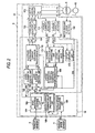
- Fig. 2 is a block diagram showing the configuration of the ECU 5 which is a control unit for the electric power-assisted steering system according to the embodiment of the invention.
- the ECU 5 is made up of a microcomputer 10 and a motor driving unit.
- the microcomputer 10 functions by executing a program stored in a memory installed therein as a motor control unit including a vehicle speed calculating unit 184, a target current calculating unit 114, subtracters 122, 124, a d-axis current PI control unit 126, a q-axis current PI control unit 128, a d-q/3-phase alternating current coordinates transforming unit 132, a sign reversal adder 134, a 3-phase alternating current/d-q coordinates transforming unit 138, a detected current correcting unit 170, and an offset updating unit 172.
- the target current calculating unit 114 includes a basic assistance control unit 180 and a motor current command value calculating unit 188.
- the motor driving unit is a hardware (a circuit) for driving the 3-phase brushless motor 6 based on a voltage command value outputted from the microcomputer 10 which functions as the motor control unit, and is made up of a PWM signal generating circuit 150, a motor driving circuit 152, a U-phase current detector 15, a V-phase current detector 154, and a rotor angular position detector 162.
- a steering torque Ts detected by the torque sensor 3 is inputted into the ECU 5, and a vehicle speed signal Vs detected by the vehicle speed sensor 4 is also inputted into the ECU 5.
- a vehicle speed V is calculated based on the vehicle speed signal Vs.
- the rotor angular position detector 162 outputs a signal indicating the position or electric angle ⁇ re of the revolving field which is the rotor of the motor 6 based on a sensor signal outputted from the position detecting sensor 12 mounted on the motor 6.
- the basic assistance control unit 180 determines a current target value It that is made to flow to the motor 6 based on the steering torque Ts and the vehicle speed v by referring to a table referred to as an assist map in which a steering torque is made to correspond to a current target value.
- the motor current command value calculating unit 188 outputs a q-axis current command value iq* based on the current target value It so determined.
- the q-axis current command value iq* outputted from the motor current command value calculating unit 188 is a current value which corresponds to a torque that is to be generated by the motor 6 and is inputted into the subtracter 124.
- the U-phase current detector 156 and the V-phase current detector 154 detect current flowing to a U-phase coil and a V-phase coil of the motor, respectively, and output a U-phase current detection signal Siu and a V-phase current detection signal Siv, respectively.
- detection resistors are inserted between power switching elements corresponding, respectively, to the U-phase and the V-phase and the grounded line within the motor driving circuit 152, and the U-phase current detector 156 and the V-phase current detector 154 output a U-phase current detection signal Siu and a V-phase current detection signal Siv, respectively, based on voltages between ends of the detection resistors so inserted.
- the U-phase current detection signal Siu and the V-phase current detection signal Siv are voltage signals which indicate the value of U-phase current which actually flows to the motor 6 and the value of V-phase current which actually flows to the motor 6, respectively, the current values indicated by these voltage signals are such that the value of offset current is superimposed on the value of current which actually flows to the motor.
- the U-phase current detection signal Siu and the V-phase current detection signal Siv are inputted into the detected current value correcting unit 170 and the offset updating unit 172.
- the U-phase current detection signal Siu and the V-phase current detection signal Siv which are analog voltage signals are inputted into the microcomputer 10 and are then converted into digital values as sampling values which indicate a U-phase current detected value and a V-phase current detected value, respectively, by an A/D converter. Then, the U-phase current detected value (hereinafter, this is indicated by a symbol “iu”) and the V-phase current detected value (hereinafter, this is indicated by a symbol “iv”), which are digital values, are inputted into the detected current value correcting unit 170 and the offset updating unit 172 which are realized by the microcomputer 10 in terms of software.
- These detected current value correcting unit 170 and the offset updating unit 172 function as correcting devices for calculating a U-phase motor current value (a U-phase current detected value after correction) imu and a V-phase motor current value (a V-phase current detected value after correction) imv by applying an offset correction to the U-phase current detected value iu and the V-phase current detected value iv.
- the detected current value correcting unit 170 retains a U-phase current detected value resulting when the U-phase current flowing to the motor 6 is zero as a U-phase offset correction value iuO and a V-phase current detected value resulting when the V-phase current flowing to the motor 6 is zero as a V-phase offset correction value ivO, respectively, and outputs the U-phase motor current value imu and the V-phase motor current value imv by correcting the U-phase current detected value iu and the V-phase current detected value iv based on the offset correction values iuO and ivO.
- the offset updating unit 172 receives sequentially fresh offset correction values from the U-phase current detected value iu and the V-phase current detected value iv and sequentially updates the offset correction values iuO and ivO which are retained in the detected current value correcting unit 170 with the fresh offset correction values so received.
- the operation of the detected current value correcting unit 170 and the offset updating unit 172 will be described in detail later on.
- the 3-phase alternating current/d-q coordinates transforming unit 138 transforms the U-phase motor current value imu and the V-phase motor current value imv into a d-axis motor current value id and a q-axis motor current value iq which are values on d-q coordinates based on the electric angle ⁇ re of the rotor.
- the d-axis motor current value id and the q-axis motor current value iq are inputted into the subtracter 122 and the subtracter 124, respectively.
- the subtracter 122 outputs a deviation id*-id between the di-axis current command value id* and the d-axis motor current value id, and the d-axis current PI control unit 126 generates a d-axis voltage command value vd* through a proportional integration operation based on the deviation id*-id.
- the subtracter 124 outputs a deviation iq*-iq between the q-axis current command value iq* and the q-axis motor current value iq, and the q-axis current PI control unit 128 generates a q-axis voltage command value vq* through a proportional integration operation based on the deviation iq*-iq.
- the d-axis voltage command value vd* and the q-axis voltage command value vq* which are so generated are then inputted into the d-q/3-phase alternating current coordinates transforming unit 132.
- the d-q/3-phase alternating current coordinates transforming unit 132 transforms the d-axis voltage command value vd* and the q-axis voltage command value vq* into a U-phase voltage command value vu* and a V-phase voltage command value vv* which are values on the 3-phase alternating current coordinates based on the electric angle ⁇ re of the rotor. Then, the sign reversal adder 134 calculates a W-phase voltage command value vw* from the U-phase voltage command value vu* and the V-phase voltage command value vv*.
- the U-phase voltage command value vu*, V-phase voltage command value vv* and W-phase voltage command value vw* which are so obtained are outputted from the microcomputer 10 to be inputted into the PWM signal generating circuit 150.
- the PWM signal generating circuit 150 generates PWM signals Su, Sv, Sw whose duty ratios vary according to the U-phase voltage command value vu*, the V-phase voltage command value vv* and the W-phase voltage command value vw*, respectively.
- the motor driving circuit 152 generates phase voltages vu, vv, vw which correspond, respectively, to the duty ratios of the PWM signals Su, Sv, Sw by switching on and off the power switching elements by the PWM signals Su, Sv, Sw.
- the motor driving circuit 152 has two FETs (field-effect transistors) which are power switching elements adapted to be switched on and off in such a manner as to oppose each other, and the PWM signal Su which corresponds to the U-phase is constituted by two PWM signals S1u and S2u which are applied to gate terminals of two FETs which correspond to the U-phase, the PWM signal Sv which corresponds to the V-phase is constituted by two PWM signals S1v and S2v which are applied to gate terminals of two FETs which correspond to the V-phase, and the PWM signal Sw which corresponds to the W-phase is constituted by two PWM signals S1w and S2w which are applied to gate terminals of two FETs which correspond to the W-phase.
- the PWM signal Su which corresponds to the U-phase is constituted by two PWM signals S1u and S2u which are applied to gate terminals of two FETs which correspond to the U-phase
- phase voltages vu, vv, vw which are generated as has just been described are then outputted from the ECU 5 so as to be applied to the motor 6.
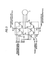
- Fig. 3 is a circuit diagram showing a first layout example of detection resistors which are inserted in the motor driving circuit 152 to detect current flowing to the respective phases of the brushless motor 6.
- Fig. 3 shows the configuration of the motor driving circuit 152, and in the circuit shown in Fig. 3 , a power supply line PWR is connected to a positive terminal of the battery 8 via an ignition switch 9, and a grounded line GND is connected to a negative terminal of the battery 8.
- a power supply line PWR is connected to a positive terminal of the battery 8 via an ignition switch 9, and a grounded line GND is connected to a negative terminal of the battery 8.
- the motor driving circuit 152 is a PWM type driving circuit and includes FETs 51U, 51V, 51W which are disposed on a power supply line PWR side and which constitute power switching elements which correspond to the U-phase, V-phase and W-phase, respectively and FETs 52U, 52V, 52W which are disposed on a grounded line GND side and which constitute power switching elements which correspond to the U-phase, V-phase and W-phase, respectively, and the power supply side FET (hereinafter, referred to as a "Hi-side FET”) 51X and the grounded line side FET (hereinafter, referred to as a "Lo-side FET”) 52X which correspond to the same phase are connected in series in such a manner as to make a pair.
- Hi-side FET Hi-side FET
- Lo-side FET grounded line side FET
- a circuit portion on the power supply line including the FETs 51U, 51V, 51W is referred to as an "upper arm", and a circuit portion on the grounded line side including the FETs 52U, 52V, 52W is referred to as a "lower arm”.
- PWM signals S1u, S1v, S1w are provided to gate terminals of the Hi-side FETs 51U, 51V, 51W, respectively, whereby the Hi-side FETs 51U, 51V, 51W are switched on and off.
- PWM signals S2u, S2v, S2w are provided to gate terminals of the Lo-side FETs 52U, 52V, 52W, respectively, whereby the Lo-side FETS 52U, 52V, 52W are switched on and off in an opposite fashion to the H-side FETs 51U, 51V, 51W, respectively.
- a detection resistor Ru for detecting current flowing to the Lo-side FET 52U or current flowing to a lower arm corresponding to the U-phase (hereinafter, referred to as a "U-phase current detection resistor") is inserted between the Lo-side FET 52U corresponding to the U-phase and the ground-side branch point NL.
- a detection resistor Rv for detecting current flowing to the Lo-side FET 52V or current flowing to a lower arm corresponding to the V-phase (hereinafter, referred to as a "V-phase current detection resistor") is inserted between the Lo-side FET 52V corresponding to the V-phase and the ground-side branch point NL.
- no detection resistor is inserted between the Lo-side FET 52W corresponding to the W-phase and the ground-side branch point NL.
- a connecting point between the Lo-side FET 52U and the U-phase current detection resistor Ru is connected to an input terminal of the U-phase current detector 156, and the U-phase current detector 156 outputs a signal indicating the electric potential Vsu of the connecting point which is so measured from the grounded line GND which constitutes a reference or a voltage between ends of the U-phase current detection resistor Ru as the previously described U-phase current detection signal Siu (refer to Fig. 2 ).
- a connecting point between the Lo-side FET 52V and the V-phase current detection resistor Rv is connected to an input terminal of the V-phase current detector 154 and the V-phase current detector 154 outputs a signal indicating the electric potential Vsv of the connecting point which is so measured from the grounded line GND which constitutes a reference or a voltage between ends of the V-phase current detection resistor Rv as the previously described V-phase current detection signal Siv.
- the U-phase current detector 156 and the V-phase current detector 154 are configured to output, respectively, a U-phase current detection signal Siu and a V-phase current detection signal Siv in such a manner that the U-phase current detection signal Siu and the v-phase current detection signal Siv take opposite polarities to the electric potentials Vsu, Vsv which are measured from the grounded line GND which constitutes the reference.
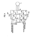
- Fig. 4 is a circuit diagram showing a second layout example of detection resistors which are inserted into the motor driving circuit 152.
- a similar configuration to the configuration shown in Fig. 3 is shown in Fig. 4 as the configuration of the motor driving circuit 152, and a U-phase current detection resistor Ru and a V-phase current detection resistor Rv are also disposed at similar positions to the layout positions shown in Fig. 3 .
- a detection resistor Rw for detecting current flowing to the Lo-side FET 52W or current flowing to a lower arm corresponding to the W-phase (hereinafter, referred to as a "W-phase current detection resistor) is inserted between the Lo-side FET 52W which corresponds to the Lo-side FET 52W and the ground-side branch point NL.
- the configuration of the ECU 5 becomes different from the configuration shown in Fig. 3 and includes the W-phase current detector in addition to the U-phase current detector 156 and the v-phase current detector 154. Then, a connecting point between the Lo-side FET 52W and the W-phase current detection resistor Rw is connected to an input terminal of the W-phase current detector, and the W-phase current detector outputs a signal indicating the electric potential Vsw of the connecting point which is so measured from the grounded line GND which constitutes a reference or a voltage between ends of the W-phase current detection resistor Rw as the W-phase current detection signal Siw.
- the W-phase current detector outputs the W-phase current detection signal Siw in such a manner that the W-phase current detection signal takes an opposite polarity to the electric potential Vsw of the connecting point which is measured from the grounded line GND which constitutes the reference.
- the detected current value correcting unit 170 calculates a U-phase motor current value imu, a v-phase motor current value imv, and a W-phase motor current value imw based on the U-phase current detection signal Siu, the v-phase current detection signal Siv and the W-phase current detection signal Siw, respectively, and the 3-phase alternating current/d-q coordinates transforming unit 138 is configured to calculate a d-axis motor current value id and a q-axis motor current value iq from the U-phase motor current value imu, V-phase motor current value imv and the W-phase motor current value imw.
- Fig. 5 is a circuit diagram showing a third layout example of detection resistors which are inserted into the motor driving circuit 152. Also in Fig. 5 , while the configuration of the motor driving circuit 152 is similar to the configuration shown in Fig. 3 , in this third layout example, detection resistors are all inserted into upper arms, which is different from the first and second layout examples in which the detection resistors Ru, Rv, Rw are inserted into the lower arms.
- a detection resistor for detecting current flowing to the Hi-side FET 51U corresponding to the U-phase or current flowing to an upper arm corresponding to the U-phase is inserted between the Hi-side FET 51U and the power supply-side branch point NH as a U-phase current detection resistor Ru.
- a detection resistor for detecting current flowing to the Hi-side FET 51V corresponding to the V-phase or current flowing to an upper arm corresponding to the V-phase is inserted between the Hi-side FET 51V and the power supply-side branch point NH as a V-phase current detection resistor Rv.
- a resistor for detecting current flowing to the Hi-side FET 51W corresponding to the W-phase or current flowing to an upper arm corresponding to the W-phase is inserted between the Hi-side FET 51W and the power supply-side branch point NH as a W-phase current detection resistor Rw.
- a connecting point between the Hi-side FET 51U and the U-phase current detection resistor Ru is connected to an input terminal of the U-phase current detector 156, and the U-phase current detector 156 outputs a signal indicating the electric potential Vsu of the connecting point which is measured from the power supply line PWR which constitutes a reference or a voltage between ends of the U-phase current detection resistor Ru as a U-phase current detection signal Siu.
- a connecting point between the Hi-side FET 51V and the V-phase current detection resistor Rv is connected to an input terminal of the V-phase current detector 154, and the V-phase current detector 154 outputs a signal indicating the electric potential Vsv which is measured from the power supply line PWR which constitutes a reference or a voltage between ends of the V-phase current detection resistor Rv as a V-phase current detection signal Siv.
- a connecting point between the Hi-side FET 51W and the W-phase current detection resistor Rw is connected to an input terminal of the W-phase current detector, and the W-phase current detector outputs a signal indicating the electric potential Vsw which is measured from the power supply line which constitutes a reference or a voltage between ends of the W-phase current detector Rw as a W-phase current detection signal Siw.
- the U-phase current detector 156, the V-phase current detector 154, and the W-phase current detector output, respectively, the U-phase current detection signal Siu, the V-phase current detection signal Siv, and the W-phase current detection signal Siw in such a manner that the U-phase current detection signal Siu, the V-phase current detection signal Siv, and the W-phase current detection signal Siw take an opposite polarity to the electric potentials Vsu, Vsv, Vsw of the connecting points which are measured from the power supply line PWR which constitute the references.
- Offset correction values iuO, ivO (, iwO) for correcting current detected values from the current detection signals Siu, Siv (, Siw) which are generated based on the detection resistors Ru, Rv (, Rw) as has been described above are obtained by the offset updating unit 172, and motor current values imu, imv (, imw) are calculated when the current detected values are corrected based on the offset correction values iuo, ivO (, iwO) by the detected current value correcting unit 170.
- the current detected signal Siu, Siv are A/D converted within the microcomputer 10 and are inputted into the offset updating unit 172 and the detected current correcting unit 10 as time series data iu, iv which comprise digital values (sampling values) indicating current detected values.
- the current detection signal Siu is sampled in not only a time period when the Lo-side FET corresponding to the U-phase (hereinafter, referred to as a "U-phase Lo-side FET") 52U is ON but also a time period when the same FET 52U is OFF, and the time series data iu made up of values of the current detection signals Siu sampled at those sampling time points (sampling values) are inputted into the offset updating unit 172 and the detected current value correcting unit 170.
- U-phase Lo-side FET the time series data iu made up of values of the current detection signals Siu sampled at those sampling time points (sampling values)
- the current detection signal Siv is sampled in not only a time period when the Lo-side FET (hereinafter, referred to as a "V-phase Lo-side FET") 52V is ON but also a time period when the same FET 52V is OFF, and the time series data iv made up of values of current detection signals Siv sampled at those sampling time points (sampling values) are inputted into the offset updating unit 172 and the detected current value correcting unit 170.
- V-phase Lo-side FET hereinafter, referred to as a "V-phase Lo-side FET”
- the offset updating unit 172 updates the U-phase offset correction value iuO which is retained in the detected current value correcting unit 170 with, of the time series data iu, iv which are made up of the current detected values as the sampling values, the sampling value sampled in the time period when the U-phase Lo-side FET 52U is OFF (hereinafter, referred to as an "OFF period sampling value") so as to constitute a new offset correction value and also updates the V-phase offset correction value ivO which is retained in the detected current value correcting unit 170 with the sampling value sampled in the time period when the V-phase Lo-side FET 52V is OFF (an OFF period sampling value) so as to constitute a new offset correction value.
- the detected current value correcting unit 170 calculates a U-phase motor current value imu by subtracting the offset correction value iuO from, of the time series data iu, iv, the sampling value sampled in the time period when the U-phase Lo-side FET 52U is ON (hereinafter, referred to as an "ON period sampling value”) and also calculates a V-phase motor current value imv by subtracting the offset correction value ivo from the sampling value sampled in the time period when the V-phase Lo-side FET 52V is ON (an ON period sampling value).
- the current detecting device for detecting a motor current in this embodiment is realized by the detection resistors Ru, Rv which are provided within the motor driving circuit 152, the U-phase current detector 156 and V-phase current detector 154, and the A/D converter provided within the microcomputer 10 for converting the current detection signals Siu, Siv into digital values.
- Fig. 6 is a signal waveform chart for explaining the detecting operation of the motor 6 according to the embodiment (in a case where the U-phase current is zero).
- the duty ratios (ratio of time period when FETs are switched on) Dr of the Hi-side FET (hereinafter, referred to as a "U-phase Hi-side FET") 51U and the Lo-side FET 52U which correspond to the U-phase are both 50%
- a PWM signal provided to a gate terminal of the U-phase Lo-side FET (hereinafter, referred to as a "U-phase Lo-side PWM signal”) 52u takes a waveform shown in Fig. 6A .
- a PWM signal provided to a gate terminal of the U-phase Hi-side FET 51U (hereinafter, referred to as a "U-phase Hi-side PWM signal”) S1u has a complementary relation to the U-phase Lo-side PWM signal S2u in order to make the U-phase Hi-side FET 51U switch on and off in an opposite fashion to the U-phase Lo-side FET 52U.
- the U-phase Hi-side PWM signal S1u becomes an L level when the U-phase Lo-side PWM signal is at an H level and becomes the H level when the U-phase PWM signal S2u is at the H level (the same applies to the following description).
- the U-phase current detection signal Siu takes a waveform shown in Fig. 6B.
- the U-phase current detection signal Siu (hereinafter, in the event that the U-phase current detection signal Siu is clearly indicated as being a function of time t, the same signal is so represented by "Siu(t)”) is sequentially converted into a U-phase current detected value iu which is a digital value by the A/D converter within the microcomputer 10 and is then inputted into the detected current value correcting unit 170 and the offset updating unit 172. In this A/D conversion, as shown in Fig.
- sampling time points are set such that the sampling value of the U-phase current detected signal Siu sampled in the time period when the U-phase Lo-side FET 52U is ON and the sampling value of the U-shape current detected signal Siu sampled in the time period when the U-phase Lo-side FET 52U is OFF appear alternately (in Fig. 6B , the sampling value sampled in the ON period is represented by a black circle, whereas the sampling value sampled in the OFF period is represented by a while circle. The same applies to charts which will be referred to later on).
- a sampling pulse for setting the sampling time points can easily be generated from, for example, a signal that is used in generating a PWM signal such as the U-phase Lo-side PWM signal S2u.
- Fig. 7 is a signal waveform chart for explaining the operation of detecting motor current when a U-phase current flows into the motor 6 from the driving circuit 152 in the embodiment of the invention (with the U-phase current being positive).
- the Lo-side PWM signal S2u takes a waveform shown in Fig. 7A .
- the U-phase Lo-side PWM signal S2U is at an H level with the U-phase Lo-side FET 52U being in the ON state, and current flows from the grounded line GND to the motor 6, which is an inductive load, via the U-phase Lo-side FET 52U. Due to this, values of the U-phase current detection signal Siu at sampling time points t2, t4, t6, ... or the ON period sampling values iu 2 , iu 4 , iu 6 ... indicate the u-phase current value of the motor 6 iu 2 , iu 4 , iu 6 ....
- the offset updating unit 172 sequentially updates the U-phase offset correction value iuO with values of the U-phase current detection signal Siu at sampling time points t1, t3, t5, ... or the OFF period sampling values iu 1 , iu 3 , iu 5 ... as new offset correction values
- Fig. 8 is a signal waveform chart for explaining the detecting operation of motor current when a U-phase current flows from the motor 6 to the driving circuit 152 in the embodiment of the invention (with the U-phase current being negative).
- the Lo-side PWM signal S2u takes a waveform shown in Fig. 8A. In this case, in a time period, as shown in Fig.
- the offset updating unit 172 sequentially updates the U-phase offset correction value iuO with values of the U-phase current detection signal Siu at sampling time points t1, t3, t5 ... or OFF period sampling values iu 1 , iu 3 , iu 5 ...
- the detected current value correcting unit 170 sequentially calculates a U-phase motor current value imu (negative) at the sampling time points t2, t4, t6 ... by subtracting the offset correction value iuO from the ON period sampling values iu 2 , iu 4 , iu 6 ...
- the sampling time points are set such that the single ON period sampling value and the single OFF period sampling value correspond, respectively, to the single ON period and single OFF period of the switching element or U-phase Lo-side FET 52U which are included in the lower arm including the detection resistors Ru, the invention is not limited thereto, and for example, the sampling time points may be set such that a plurality of ON period sampling values and a plurality of OFF period sampling values correspond, respectively, to to the single ON period and single OFF period.
- the PWM type driving circuit is used, and not only current in the time period when the FET, which is the switching element within the lower arm, is ON but also current in the time period when the FET is OFF are sequentially detected by the detection resistors Ru, Rv which are inserted into the lower arms or upper arms of the driving circuit (refer to Figs. 6 to 8 ).
- the offset correction value iuO is sequentially updated by the current detected values (iu 1 , iu 3 , iu 5 ...) in the time period when the FET is OFF, and the motor current values imu and imv are sequentially calculated when the current detected values (iu 2 , iu 4 , iu 6 ...) in the time period when the FET is ON are corrected by the offset correction value iuo, whereby the driving of the motor 6 is controlled using these motor current values imu and imv (refer to Fig. 2 ).
- the update of the retained offset correction values iuO, ivo can be implemented at any time based on the latest measured value, and moreover, there is no need to set the electric power-assisted steering system in the special state in order to obtain an offset correction value as a measured value, whereby there is obtained an advantage that the generation of torque ripple in the brushless motor 6 can be suppressed, thereby making it possible to provide the electric power-assisted steering system which does not make the driver feel a feeling of physical disorder when manipulating the steering wheel.
- the number of phases of the motor 6 may be equal to or larger than four, and the detection resistor may be inserted in the upper arm or lower arm which includes one of the power supply-side switching element and the ground-side switching element in such a manner that current flowing to the one of the power supply-side and ground-side switching elements in each arm or predetermined arms (the number of arms is smaller by one than the number of phases) in the driving circuit.
- the invention can be applied, provided that the PWM type driving circuit is used. Then, the current detected values are sequentially obtained when the one of the power supply-side switching element and the ground-side switching element in each arm or predetermined arms in the driving circuit is both in the ON state and OFF state by means of the device for detecting the current flowing to the one of the switching elements, whereby the update of the offset correction value for correcting the offset error in the detection of motor current with the measured value can be enabled at any time, thereby making it possible to provide the electric power-assisted steering system which does not make the driver feel a feeling of physical disorder when manipulating the steering wheel.
- the detection resistor is inserted in the upper arm or lower arm in the motor driving circuit 152
- the current detecting device is not limited to one utilizing the detection resistors, and a configuration may be adopted in which other detecting elements are used instead of the detection resistors for detecting current flowing to the upper arm or lower arm.
- the invention can be applied to a hydraulic power-assisted steering system in which the steering assistance is provided by hydraulic pressure from a pump driving by an electric motor in order to detect current flowing to the electric motor.
Landscapes
- Engineering & Computer Science (AREA)
- Chemical & Material Sciences (AREA)
- Combustion & Propulsion (AREA)
- Transportation (AREA)
- Mechanical Engineering (AREA)
- Power Engineering (AREA)
- Control Of Motors That Do Not Use Commutators (AREA)
- Power Steering Mechanism (AREA)
- Control Of Ac Motors In General (AREA)
- Steering Control In Accordance With Driving Conditions (AREA)
Claims (3)
- Servolenkung zum Aufbringen einer Hilfslenkkraft auf einen Lenkmechanismus eines Fahrzeugs durch Antreiben eines Elektromotors (6) auf der Basis eines Sollwerts, der durch eine Betätigung einer Betätigungseinheit zum Lenken des Fahrzeugs bestimmt ist, wobei die Servolenkung aufweist:eine PWM-Antriebsschaltung (5), die ein Schaltelementepaar (152) mit einem ersten Schaltelement (51U, 51V, 51W), das an einer Stromzuführungsseite (PWR) angeordnet ist, und mit einem zweiten Schaltelement (52U, 52V, 52W) umfasst, das an einer Erdungsleitungsseite (GND) angeordnet ist, und die miteinander in Reihe geschaltet sind, wobei sie eingerichtet ist, um dem Elektromotor (6) Strom von einem Verbindungspunkt (Nu, Nv, Nw) zwischen dem ersten Schaltelement (51 U, 51V, 51W) und dem zweiten Schaltelement (52U, 52V, 52W) zuzuführen;einen Stromdetektor (154, 156), der einen Strom erfassen kann, der zu einem, entweder dem ersten Schaltelement (51U, 51V, 51W) oder dem zweiten Schaltelement (52U, 52V, 52W), fließt;dadurch gekennzeichnet,- dass eine Korrektureinheit (170, 172) einen erfassten Wert des Stroms (iu, iv) erfassen kann, der durch den Stromdetektor (154, 156) erfasst ist, wenn das eine der ersten und zweiten Schaltelemente (51 U, 51 V, 51W; 52U, 52V, 52W) sich in einem Ein-Zustand auf der Basis eines erfassten Stromwerts (iu, iv) befindet, der durch den Stromdetektor (154, 156) erfasst ist, und wenn das andere der ersten und zweiten Schaltelemente (51U, 51V, 51W; 52U, 52V, 52W) sich in einem Aus-Zustand befindet, und die Einheit den korrigierten erfassten Wert (imu, imv) ausgeben kann; und- dass ein Steuergerät das Antreiben des Elektromotors (6) durch Ein- und Ausschalten des ersten Schaltelements (51U, 51V, 51W) und des zweiten Schaltelements (52U, 52V, 52W) auf der Basis des Soll-Werts (It) und des korrigierten erfassten Werts (imu, imv) steuern kann.
- Servolenkung gemäß Anspruch 1, wobei der Stromdetektor (154, 156) einen Strom (iu, iv) erfassen kann, der zu einem der ersten und zweiten Schaltelemente (51 U, 51V, 51W; 52U, 52V, 52W) in jeder Periode fließt, wenn das eine der ersten und zweiten Schaltelemente (51U, 51V, 51W; 52U, 52V, 52W) in den EIN-Zustand gebracht wird, und in jeder Periode fließt, wenn das andere der ersten und zweiten Schaltelemente (51U, 51V, 51W; 52U, 52V, 52W) in den AUS-Zustand gebracht wird, und wobei die Korrektur-Einheit (170, 172) umfasst:- eine Korrektureinheit (170) des erfassten Stromwerts, die als Verschiebungskorrekturwert den erfassten Stromwert (iu, iv) beibehalten kann, der durch den Stromdetektor (154, 156) erfasst ist, wenn sich das eine der ersten und zweiten Schaltelemente (51 U, 51V, 51 W; 52U, 52V, 52W) im AUS-Zustand befindet, den erfassten Stromwert (iu, iv) korrigieren kann, der durch den Stromdetektor (154, 156) erfasst ist, wenn sich das eine der ersten und zweiten Schaltelemente im EIN-Zustand auf der Basis des Verschiebungs-Korrektur-Werts befindet, und den korrigierten erfassten Wert (imu, imv) nach der Korrektur ausgeben kann; und- eine Verschiebungs-Aktualisierungs-Einheit (172), die als neuen Verschiebungs-Korrektur-Wert den beibehaltenen Verschiebungs-Korrektur-Wert mit einem erfassten Stromwert (iu, iv) aktualisieren kann, der durch den Stromdetektor (154, 156) erfasst ist, wenn sich das eine der ersten und zweiten Schaltelemente (51U, 51V, 51W; 52U, 52V, 52W) im AUS-Zustand befindet.
- Servolenkung gemäß Anspruch 1, wobei der Stromdetektor (154, 156) einen Erfassungswiderstand (Ru, Rv, Rw) umfasst, der zwischen dem einen der ersten und zweiten Schaltelemente (51U, 51V, 51W; 52U, 52V, 52W) und der Stromzuführungsseite (PWR) oder der Erdungsleitungsseite (GND) eingesetzt ist, und der den Strom erfassen kann, der zu einem der ersten und zweiten Schaltelemente (51 U, 51 V, 51 W; 52U, 52V, 52W) auf der Basis einer Spannung (Vsu, Vsv, Vsw) zwischen gegenüberliegenden Enden des Erfassungswiderstands (Ru, Rv, Rw) fließt.
Applications Claiming Priority (2)
| Application Number | Priority Date | Filing Date | Title |
|---|---|---|---|
| JP2003362217 | 2003-10-22 | ||
| JP2003362217A JP4474896B2 (ja) | 2003-10-22 | 2003-10-22 | パワーステアリング装置 |
Publications (3)
| Publication Number | Publication Date |
|---|---|
| EP1526060A2 EP1526060A2 (de) | 2005-04-27 |
| EP1526060A3 EP1526060A3 (de) | 2011-10-12 |
| EP1526060B1 true EP1526060B1 (de) | 2013-07-31 |
Family
ID=34386509
Family Applications (1)
| Application Number | Title | Priority Date | Filing Date |
|---|---|---|---|
| EP04025238.9A Expired - Lifetime EP1526060B1 (de) | 2003-10-22 | 2004-10-22 | Servolenksystem |
Country Status (4)
| Country | Link |
|---|---|
| US (1) | US7040450B2 (de) |
| EP (1) | EP1526060B1 (de) |
| JP (1) | JP4474896B2 (de) |
| KR (1) | KR20050039630A (de) |
Families Citing this family (47)
| Publication number | Priority date | Publication date | Assignee | Title |
|---|---|---|---|---|
| JP4371844B2 (ja) * | 2004-02-16 | 2009-11-25 | 株式会社デンソー | ブラシレスモータ駆動装置 |
| JP4030528B2 (ja) * | 2004-06-16 | 2008-01-09 | 三菱電機株式会社 | 電動パワーステアリング制御装置における駆動電流オフセットの調整方法 |
| JP4289458B2 (ja) * | 2004-09-07 | 2009-07-01 | 三菱電機株式会社 | 電動パワーステアリング制御装置 |
| US7483796B2 (en) * | 2004-12-08 | 2009-01-27 | Trw Automotive U.S. Llc | Method and apparatus for determining faults in an electric assist steering system |
| JP2007006566A (ja) * | 2005-06-22 | 2007-01-11 | Hitachi Ltd | モータ制御装置 |
| JP4738095B2 (ja) * | 2005-08-17 | 2011-08-03 | 三洋電機株式会社 | 電流検出回路の故障検出方法 |
| JP2007135374A (ja) * | 2005-11-14 | 2007-05-31 | Aisin Seiki Co Ltd | モータ駆動電流検出装置 |
| CN101365616B (zh) * | 2005-11-23 | 2011-12-21 | Trw汽车美国有限责任公司 | 电动助力转向系统 |
| JP4727405B2 (ja) * | 2005-12-08 | 2011-07-20 | 本田技研工業株式会社 | 電動機の制御装置 |
| JP4816257B2 (ja) * | 2006-05-31 | 2011-11-16 | 日本精工株式会社 | モータ制御装置 |
| JP5070867B2 (ja) * | 2007-02-05 | 2012-11-14 | 株式会社ジェイテクト | モータ制御装置及び電動パワーステアリング装置 |
| JP5168448B2 (ja) | 2007-02-26 | 2013-03-21 | 株式会社ジェイテクト | モータ制御装置及び電動パワーステアリング装置 |
| EP1990256B1 (de) * | 2007-05-08 | 2011-06-15 | Jtekt Corporation | Elektrische Servolenkung |
| US7969124B2 (en) * | 2007-06-01 | 2011-06-28 | Advantest Corporation | Power supply apparatus, test apparatus, and electronic device |
| JP5056175B2 (ja) * | 2007-06-01 | 2012-10-24 | 株式会社ジェイテクト | モータ制御装置及び電動パワーステアリング装置 |
| JP5014034B2 (ja) | 2007-09-12 | 2012-08-29 | オムロンオートモーティブエレクトロニクス株式会社 | 多相交流モータ駆動装置 |
| JP2009232569A (ja) * | 2008-03-21 | 2009-10-08 | Nsk Ltd | モータ駆動制御装置及びこれを使用した電動パワーステアリング装置 |
| JP4803286B2 (ja) * | 2009-07-31 | 2011-10-26 | 株式会社デンソー | 車両の走行用モータ制御装置 |
| JP5018850B2 (ja) * | 2009-09-28 | 2012-09-05 | 三菱電機株式会社 | 電動機制御装置 |
| JP5412360B2 (ja) * | 2010-04-07 | 2014-02-12 | 株式会社ショーワ | 電動パワーステアリング装置 |
| WO2011142032A1 (ja) * | 2010-05-14 | 2011-11-17 | 三菱電機株式会社 | ブラシレスモータの駆動装置 |
| JP5463215B2 (ja) * | 2010-06-21 | 2014-04-09 | 日立オートモティブシステムズ株式会社 | 電動パワーステアリング用モータの制御装置 |
| US8674713B2 (en) * | 2010-10-21 | 2014-03-18 | Tektronix, Inc. | Zero ampere level current data correction for a power device under test |
| JP2013046514A (ja) * | 2011-08-25 | 2013-03-04 | Semiconductor Components Industries Llc | 駆動信号生成回路 |
| JP5850406B2 (ja) * | 2012-04-02 | 2016-02-03 | 株式会社デンソー | モータ駆動装置 |
| US9676409B2 (en) | 2013-03-11 | 2017-06-13 | Steering Solutions Ip Holding Corporation | Road wheel disturbance rejection based on hand wheel acceleration |
| US10155531B2 (en) | 2013-04-30 | 2018-12-18 | Steering Solutions Ip Holding Corporation | Providing assist torque without hand wheel torque sensor |
| JP6076854B2 (ja) | 2013-08-07 | 2017-02-08 | Jxエネルギー株式会社 | 炭化水素油中の水銀の除去方法 |
| JP5983567B2 (ja) | 2013-09-10 | 2016-08-31 | トヨタ自動車株式会社 | 電動機制御装置 |
| US9540044B2 (en) | 2013-11-15 | 2017-01-10 | Steering Solutions Ip Holding Corporation | Hand wheel angle from vehicle dynamic sensors or wheel speeds |
| CN106031019B (zh) * | 2014-02-21 | 2018-07-27 | 三菱电机株式会社 | 交流旋转机的控制装置以及电动助力转向的控制装置 |
| US9540040B2 (en) | 2014-06-26 | 2017-01-10 | Steering Solutions Ip Holding Corporation | Phase plane based transitional damping for electric power steering |
| US10144445B2 (en) | 2014-09-15 | 2018-12-04 | Steering Solutions Ip Holding Corporation | Modified static tire model for providing assist without a torque sensor for zero to low vehicle speeds |
| US9409595B2 (en) * | 2014-09-15 | 2016-08-09 | Steering Solutions Ip Holding Corporation | Providing assist torque without hand wheel torque sensor for zero to low vehicle speeds |
| CN107438943B (zh) * | 2015-03-12 | 2020-09-04 | 三菱电机株式会社 | 交流旋转电机的控制装置和电动助力转向系统的控制装置 |
| JP6443256B2 (ja) * | 2015-07-31 | 2018-12-26 | 株式会社デンソー | センサ装置 |
| US10336363B2 (en) | 2015-09-03 | 2019-07-02 | Steering Solutions Ip Holding Corporation | Disabling controlled velocity return based on torque gradient and desired velocity error |
| US10464594B2 (en) | 2015-09-03 | 2019-11-05 | Steering Solutions Ip Holding Corporation | Model based driver torque estimation |
| US9873450B2 (en) * | 2016-02-16 | 2018-01-23 | Steering Solutions Ip Holding Corporation | Detection of offset errors in phase current measurement for motor control system |
| US9966890B2 (en) * | 2016-02-16 | 2018-05-08 | Steering Solutions Ip Holding Corporation | Detection of offset errors in phase current measurement for motor control system |
| JP2017197137A (ja) * | 2016-04-28 | 2017-11-02 | 株式会社ジェイテクト | 電動パワーステアリング装置 |
| US10155534B2 (en) | 2016-06-14 | 2018-12-18 | Steering Solutions Ip Holding Corporation | Driver intent estimation without using torque sensor signal |
| DE102017203457A1 (de) * | 2017-03-02 | 2018-09-06 | Volkswagen Aktiengesellschaft | Strommessverfahren, Betriebsverfahren, Lenkhilfe, Computerprogrammerzeugnis und Arbeitsvorrichtung |
| JP7234737B2 (ja) * | 2019-03-28 | 2023-03-08 | 株式会社デンソー | 検出ユニット |
| JP7475789B2 (ja) * | 2020-12-25 | 2024-04-30 | アルプスアルパイン株式会社 | モータ制御装置 |
| US11799394B2 (en) * | 2021-02-09 | 2023-10-24 | Steering Solutions Ip Holding Corporation | Inverter phase switch with high side vs low side MOSFET resistance diversity |
| WO2023157432A1 (ja) | 2022-02-18 | 2023-08-24 | 日本精工株式会社 | 電流検出装置、モータ制御装置及び電動パワーステアリング装置 |
Family Cites Families (12)
| Publication number | Priority date | Publication date | Assignee | Title |
|---|---|---|---|---|
| JP2847406B2 (ja) | 1989-12-15 | 1999-01-20 | 光洋精工株式会社 | 電動機の電流検出回路 |
| JPH08119132A (ja) | 1994-10-20 | 1996-05-14 | Koyo Seiko Co Ltd | 電動パワーステアリング装置 |
| JP3460885B2 (ja) * | 1995-03-09 | 2003-10-27 | 三菱電機株式会社 | 電動パワーステアリング制御装置 |
| JP3154665B2 (ja) * | 1996-08-29 | 2001-04-09 | 三菱電機株式会社 | ハイサイド方式のモータ電流検出回路 |
| JP3390333B2 (ja) * | 1997-08-27 | 2003-03-24 | 本田技研工業株式会社 | 電動パワーステアリング装置 |
| JP3644835B2 (ja) * | 1999-01-18 | 2005-05-11 | 三菱電機株式会社 | 電動式パワーステアリング回路装置 |
| US7103661B2 (en) * | 2000-07-12 | 2006-09-05 | John Raymond Klein | Auto configuration of portable computers for use in wireless local area networks |
| JP2003160053A (ja) * | 2001-11-28 | 2003-06-03 | Toyoda Mach Works Ltd | 電気式動力舵取装置 |
| US6808043B2 (en) * | 2002-02-15 | 2004-10-26 | Nsk Ltd. | Electric power steering device |
| US6995679B2 (en) * | 2002-04-30 | 2006-02-07 | International Rectifier Corporation | Electronically controlled power steering system for vehicle and method and system for motor control |
| JP3967642B2 (ja) * | 2002-07-26 | 2007-08-29 | 株式会社ジェイテクト | 車両用操舵制御システム |
| JP2004330883A (ja) * | 2003-05-07 | 2004-11-25 | Denso Corp | 伝達比可変操舵装置 |
-
2003
- 2003-10-22 JP JP2003362217A patent/JP4474896B2/ja not_active Expired - Fee Related
-
2004
- 2004-10-21 US US10/969,006 patent/US7040450B2/en not_active Expired - Lifetime
- 2004-10-22 KR KR1020040084678A patent/KR20050039630A/ko not_active Ceased
- 2004-10-22 EP EP04025238.9A patent/EP1526060B1/de not_active Expired - Lifetime
Also Published As
| Publication number | Publication date |
|---|---|
| US20050125124A1 (en) | 2005-06-09 |
| EP1526060A3 (de) | 2011-10-12 |
| JP2005130578A (ja) | 2005-05-19 |
| KR20050039630A (ko) | 2005-04-29 |
| US7040450B2 (en) | 2006-05-09 |
| JP4474896B2 (ja) | 2010-06-09 |
| EP1526060A2 (de) | 2005-04-27 |
Similar Documents
| Publication | Publication Date | Title |
|---|---|---|
| EP1526060B1 (de) | Servolenksystem | |
| EP2262098B1 (de) | Motorsteuerungsvorrichtung und elektrische servolenkung | |
| US10494017B2 (en) | Electric power steering apparatus | |
| EP2159132B1 (de) | Motorsteuervorrichtung und elektrische Servolenkungsvorrichtung | |
| US9371087B2 (en) | Power conversion device and electric power steering device using the same | |
| US9248852B2 (en) | Electric power steering system | |
| US8890459B2 (en) | Motor control device and electric power steering system | |
| JP3480843B2 (ja) | 電動パワーステアリング制御装置及び制御方法 | |
| US8981687B2 (en) | Motor control apparatus and electric power steering apparatus using the same | |
| US9124211B2 (en) | Rotary electric machine control apparatus | |
| CN100522721C (zh) | 电动式动力转向装置,及检测其角度检测器异常的方法 | |
| US8710775B2 (en) | Electric power steering apparatus | |
| US20150077025A1 (en) | Power conversion apparatus and electric power steering apparatus having the same | |
| US20150075898A1 (en) | Power conversion apparatus and electric power steering apparatus having the same | |
| US10333440B2 (en) | Motor control apparatus and electric power steering system | |
| CN101981806A (zh) | 电动机控制器和电动助力转向设备 | |
| US7226069B2 (en) | Power-assisted steering system and difference compensating method for current detector | |
| US11716048B2 (en) | Rotary electric machine control device | |
| CN107922000A (zh) | 马达控制装置、电动助力转向装置及车辆 | |
| US9707993B2 (en) | Electric power steering apparatus | |
| US20050051379A1 (en) | Electric power steering apparatus | |
| US20200395882A1 (en) | Electric power steering apparatus | |
| WO2022153941A1 (ja) | モータ制御装置 | |
| US10673360B2 (en) | Motor controller | |
| JP2020058111A (ja) | 電流検出回路の調整方法 |
Legal Events
| Date | Code | Title | Description |
|---|---|---|---|
| PUAI | Public reference made under article 153(3) epc to a published international application that has entered the european phase |
Free format text: ORIGINAL CODE: 0009012 |
|
| AK | Designated contracting states |
Kind code of ref document: A2 Designated state(s): AT BE BG CH CY CZ DE DK EE ES FI FR GB GR HU IE IT LI LU MC NL PL PT RO SE SI SK TR |
|
| AX | Request for extension of the european patent |
Extension state: AL HR LT LV MK |
|
| RAP1 | Party data changed (applicant data changed or rights of an application transferred) |
Owner name: JTEKT CORPORATION |
|
| PUAL | Search report despatched |
Free format text: ORIGINAL CODE: 0009013 |
|
| AK | Designated contracting states |
Kind code of ref document: A3 Designated state(s): AT BE BG CH CY CZ DE DK EE ES FI FR GB GR HU IE IT LI LU MC NL PL PT RO SE SI SK TR |
|
| AX | Request for extension of the european patent |
Extension state: AL HR LT LV MK |
|
| RIC1 | Information provided on ipc code assigned before grant |
Ipc: B62D 5/04 20060101AFI20110907BHEP |
|
| 17P | Request for examination filed |
Effective date: 20120412 |
|
| AKX | Designation fees paid |
Designated state(s): DE FR |
|
| GRAP | Despatch of communication of intention to grant a patent |
Free format text: ORIGINAL CODE: EPIDOSNIGR1 |
|
| RIN1 | Information on inventor provided before grant (corrected) |
Inventor name: UEDA, TAKESHI Inventor name: NAGASE, SHIGEKI Inventor name: SAKAMAKI, MASAHIKO |
|
| GRAS | Grant fee paid |
Free format text: ORIGINAL CODE: EPIDOSNIGR3 |
|
| GRAA | (expected) grant |
Free format text: ORIGINAL CODE: 0009210 |
|
| AK | Designated contracting states |
Kind code of ref document: B1 Designated state(s): DE FR |
|
| REG | Reference to a national code |
Ref country code: DE Ref legal event code: R096 Ref document number: 602004042887 Country of ref document: DE Effective date: 20130926 |
|
| PLBE | No opposition filed within time limit |
Free format text: ORIGINAL CODE: 0009261 |
|
| STAA | Information on the status of an ep patent application or granted ep patent |
Free format text: STATUS: NO OPPOSITION FILED WITHIN TIME LIMIT |
|
| 26N | No opposition filed |
Effective date: 20140502 |
|
| REG | Reference to a national code |
Ref country code: DE Ref legal event code: R097 Ref document number: 602004042887 Country of ref document: DE Effective date: 20140502 |
|
| REG | Reference to a national code |
Ref country code: FR Ref legal event code: PLFP Year of fee payment: 13 |
|
| REG | Reference to a national code |
Ref country code: FR Ref legal event code: PLFP Year of fee payment: 14 |
|
| REG | Reference to a national code |
Ref country code: FR Ref legal event code: PLFP Year of fee payment: 15 |
|
| PGFP | Annual fee paid to national office [announced via postgrant information from national office to epo] |
Ref country code: FR Payment date: 20200914 Year of fee payment: 17 |
|
| PGFP | Annual fee paid to national office [announced via postgrant information from national office to epo] |
Ref country code: DE Payment date: 20201006 Year of fee payment: 17 |
|
| REG | Reference to a national code |
Ref country code: DE Ref legal event code: R119 Ref document number: 602004042887 Country of ref document: DE |
|
| PG25 | Lapsed in a contracting state [announced via postgrant information from national office to epo] |
Ref country code: DE Free format text: LAPSE BECAUSE OF NON-PAYMENT OF DUE FEES Effective date: 20220503 |
|
| PG25 | Lapsed in a contracting state [announced via postgrant information from national office to epo] |
Ref country code: FR Free format text: LAPSE BECAUSE OF NON-PAYMENT OF DUE FEES Effective date: 20211031 |