EP1526069B1 - Elektrisch gesteuerte Getriebeschalteinrichtung für Fahrräder - Google Patents
Elektrisch gesteuerte Getriebeschalteinrichtung für Fahrräder Download PDFInfo
- Publication number
- EP1526069B1 EP1526069B1 EP05001405A EP05001405A EP1526069B1 EP 1526069 B1 EP1526069 B1 EP 1526069B1 EP 05001405 A EP05001405 A EP 05001405A EP 05001405 A EP05001405 A EP 05001405A EP 1526069 B1 EP1526069 B1 EP 1526069B1
- Authority
- EP
- European Patent Office
- Prior art keywords
- shift control
- control switch
- brake lever
- downshifting
- upshifting
- Prior art date
- Legal status (The legal status is an assumption and is not a legal conclusion. Google has not performed a legal analysis and makes no representation as to the accuracy of the status listed.)
- Expired - Lifetime
Links
Images


Classifications
-
- B—PERFORMING OPERATIONS; TRANSPORTING
- B62—LAND VEHICLES FOR TRAVELLING OTHERWISE THAN ON RAILS
- B62K—CYCLES; CYCLE FRAMES; CYCLE STEERING DEVICES; RIDER-OPERATED TERMINAL CONTROLS SPECIALLY ADAPTED FOR CYCLES; CYCLE AXLE SUSPENSIONS; CYCLE SIDECARS, FORECARS, OR THE LIKE
- B62K23/00—Rider-operated controls specially adapted for cycles, i.e. means for initiating control operations, e.g. levers, grips
- B62K23/02—Rider-operated controls specially adapted for cycles, i.e. means for initiating control operations, e.g. levers, grips hand actuated
- B62K23/06—Levers
-
- B—PERFORMING OPERATIONS; TRANSPORTING
- B62—LAND VEHICLES FOR TRAVELLING OTHERWISE THAN ON RAILS
- B62M—RIDER PROPULSION OF WHEELED VEHICLES OR SLEDGES; POWERED PROPULSION OF SLEDGES OR SINGLE-TRACK CYCLES; TRANSMISSIONS SPECIALLY ADAPTED FOR SUCH VEHICLES
- B62M25/00—Actuators for gearing speed-change mechanisms specially adapted for cycles
- B62M25/08—Actuators for gearing speed-change mechanisms specially adapted for cycles with electrical or fluid transmitting systems
Definitions
- the present invention is directed to control devices for bicycle transmissions and, more particularly, to an electrical shift control device for a bicycle transmission.
- An electrical shift control device for a bicycle transmission according to the preamble of claim 1 is already known from DE 19608088 .
- the present invention provides an electrical shift control device for a bicycle transmission in accordance with claim 1.
- a preferred embodiment of the present invention provides an electrical shift control device for a bicycle that allows the rider to carry out braking and shifting operations more quickly by mounting the electrical control switches in proximity to the brake lever used to operate the brakes.
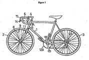
- FIG. 1 is a side view of a bicycle that includes a particular embodiment of an electrical shift control device according to the present invention.
- the bicycle comprises a chassis frame 1, a front wheel 2 and rear wheel 3 that support the chassis frame 1, a handlebar frame 4, and so on.
- the handlebar frame 4 is provided integrally with a front wheel fork 5, and a handlebar 6 is provided as part of the handlebar frame.
- a plurality of grips 7A, 7B and 7C are provided to a plurality of locations on the handlebar 6. There is no need to specify where the grips go on the handlebar.
- a moving sensor 9 is attached to one of the spokes 8 of the front wheel 2, and a stationary sensor 11 is fixed to the chassis frame 1.
- the stationary sensor 11 is able to output a single electrical pulse while the moving sensor 9 makes one revolution so that the periodic function sequence of the wheel may be determined by these sensors in a well known manner. Thus, the method by which this is determined will not be described here.
- the proper shift step is determined from this periodic function sequence by a computer.
- the bicycle electric shifting mechanism pertaining to the present invention is particularly effective when used as the actuation switch for such an automatic shifting mechanism.
- the shifting mechanism comprises a rear axle shifting mechanism 12A and a crank spindle shifting mechanism 12B.
- the shifting mechanism is a known, common mechanism that includes a derailleur.
- a shift command eletric switch 14 is provided at a suitable location on the bicycle.
- a suitable location is the brake lever 15 that moves with respect to the handlebar.
- the brake lever 15 is located ahead of the grip 7C so that the grip 7C and the brake lever 15 can be gripped simultaneously with just one hand.
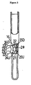
- FIGS 2 and 3 are detailed illustrations of the positional relation between the brake lever 15 and the electric switch 14.
- the direction in which the bicycle is traveling is indicated by the arrow A in Figure 3 .
- the brake lever 15 is attached to the handlebar (not shown in Figures 2 and 3 ) via an attachment component 16.
- the attachment component 16 may be included in the handlebar. If we call the surface of the brake lever 15 that is ahead in the forward direction the front side, then the electric switch 14 is attached to the back side of the brake lever 15.
- the electric switch 14 comprises toggling movable portions 22D and 22U, a return spring 20, moving electrical contacts 24D and 24U, and stationary electrical contacts 25D and 25U.
- the toggling movable portions 22D and 22U are formed from two bulging portions that bulge out in both directions from the center (above and below).
- the suffixes D and U stand for downshift and upshift, respectively.
- the bulging portions 22D and 22U move in mutually opposite directions, and move reciprocally over an approximate arc.
- the upper bulging portion 22D has an upper inclined surface 23D, which is a pressing surface
- the lower bulging portion 22U has a lower inclined surface 23U, which is also a pressing surface. The surface of the finger comes into contact with these inclined surfaces. After the finger has been removed, the toggling movable portions 22D and 22U are able to return to the depicted middle position through the work of the spring 20.
- the plane in which the upper bulging portion 22D and the lower bulging portion 22U are displaced is a vertical plane. This vertical plane is perpendicular to the forward direction A.
- the upper bulging portion 22D and the lower bulging portion 22U move roughly horizontally, in a direction approximately perpendicular to the forward direction.
- the moving electrical contacts 24D and 24U are formed from an upper moving electrical contact 24D and a lower moving electrical contact 24U.
- the upper moving electrical contact 24D is fixed to the upper bulging portion 22D
- the lower moving electrical contact 24U is fixed to the lower bulging portion 22U.
- the stationary electrical contacts 25D and 25U are formed from an upper stationary electrical contact 25D and a lower stationary electrical contact 25U.
- the lower bulging portion 22U, the lower moving electrical contact 24U, and the lower stationary electrical contact 25U may be termed a first electric switch.
- the upper bulging portion 22D, the upper moving electrical contact 24D, and the upper stationary electrical contact 25D may be termed a second electric switch.
- the first electric switch generates an electrical signal for actuating the shifting mechanisms 12A and 12B in the direction in which the gear is raised
- the second electric switch generates an electrical signal for actuating the shifting mechanisms 12A and 12B in the direction in which the gear is lowered. No electrical signal is generated in the middle position,
- a single electrical signal in the upshift direction raises the gear by one step
- a single electrical signal in the down-shift direction lowers the gear by one step.
- the thumb rests against the grip 7C of the handlebar 6, and the other fingers go around the front of the brake lever 15, with the surface of the fingertip of one finger (the surface on the palm side) resting on the toggling movable portions of the switch 14.
- the upper bulging portion 22D is pressed to the left (or right).
- the lower bulging portion 22U is pressed to the left (or right).
- the shift step can be changed by two gears by pressing the toggling movable portions 22D or 22U twice.
- Figures 4 and 5 are views of an alternative embodiment of an electrical shift control device according to the present invention.
- the fact that the electric switch 14 comprises a first electric switch and a second electric switch is the same as in the first embodiment, but this embodiment differs from the first embodiment in that the first electric switch is provided to the brake lever 15, and the second electric switch is not provided to the brake lever 15.
- the first electric switch is not formed as a toggle switch. Instead, a first electric switch 14U moves reciprocally in only one direction and generates an up-shift electrical signal, The fact that the movement plane is a vertical plane, and this vertical plane is perpendicular to the forward direction is the same as in the first embodiment. When the finger is removed, the first electric switch 14U returns to its home position and does not generate an electrical signal, The structure of the internal contacts will not be described.
- Second and third electric switches 14DF and 14DR are provided to two different locations.
- the second electric switch 14DF is mounted on the front of the attachment component (brake lever bracket) 16 adjacent to and directly above the brake lever 15, and the third electric switch 14DR is mounted on the rear of the attachment component 16 adjacent to the handlebar 6.
- the movement direction of the movable component of the second electric switch 14DF lies in a vertical plane that includes the forward direction line and intersects the horizontal direction at an angle.
- the movement direction of the movable component of the third switch 14DR lies in a vertical plane that includes the forward direction line and intersects the horizontal direction at an angle.
- the second electric switch 14DF and the third electric switch 14DR are positioned so that they can be easily pressed with the thumb of the hand firmly gripping the handlebar or the handlebar integral component.
- the gear is lowered with the second and third electric switches just before the rider forcefully tries to transmit pedaling force to the crank in order to make a transition from a high speed state to another high speed state via a low speed state. Since two electric switches 14DF and 14DR are provided, the rider can execute a quick down-shift by selecting the switch that is closer to the portion of the handlebar gripped up to that point.
- the electric switch was used to change gears, but it can be used as a switch for actuating a shifting mechanism when the shift step decision is made automatically.
- the electric switch is provided to the handlebar as well, and not just to the brake lever, so the shifting can be carried out smoothly and quickly.
- at least one of the first and second types of electric switches can be provided to the handlebar (including the bracket) or to the chassis frame that supports the rider's body (the chassis frame that supports the crank spindle).
Landscapes
- Engineering & Computer Science (AREA)
- Mechanical Engineering (AREA)
- Chemical & Material Sciences (AREA)
- Combustion & Propulsion (AREA)
- Transportation (AREA)
- Arrangement Or Mounting Of Control Devices For Change-Speed Gearing (AREA)
- Steering Devices For Bicycles And Motorcycles (AREA)
- Mechanical Control Devices (AREA)
Claims (9)
- Eine elektrische Schaltsteuervorrichtung für ein Fahrradgetriebe, die Folgendes beinhaltet:einen Bremsgriff (15), der angepasst ist, um sich relativ zu einer Lenkstange (6) zu bewegen;einen Bremsgriffträger (16) zum Montieren des Bremsgriffs (15) an der Lenkstange (6);einen Hochschalt-Schaltsteuerschalter, der an dem Bremsgriffträger (16) gestützt ist; undeinen Herunterschalt-Schaltsteuerschalter (14DR);wobei der Hochschalt-Schaltsteuerschalter und der Herunterschalt-Schaltsteuerschalter (14DR) direkt per Hand betrieben werden können,dadurch gekennzeichnet, dass der Herunterschalt-Schaltsteuerschalter (14DR) an dem Bremsgriffträger (16) gestützt ist und der Hochschalt-Schaltsteuerschalter und der Herunterschalt-Schaltsteuerschalter (14DR) auf einer äußeren Oberfläche des Bremsgriffträgers (16) angeordnet sind.
- Vorrichtung gemäß Anspruch 1, wobei einer der oder beide Hochschalt- und Herunterschalt-Schaltsteuerschalter an einer Seitenwand des Bremsgriffträgers (16) gestützt sind.
- Vorrichtung gemäß Anspruch 1 oder Anspruch 2, wobei einer der oder beide Hochschalt- und Herunterschalt-Schaltsteuerschalter an einer inneren Seitenwand des Bremsgriffträgers (16) gestützt sind.
- Vorrichtung gemäß einem der vorhergehenden Ansprüche, wobei einer der oder beide Hochschalt- und Herunterschalt-Schaltsteuerschalter angepasst sind, um unter Verwendung des Daumens eines Fahrers betrieben zu werden.
- Vorrichtung gemäß einem der vorhergehenden Ansprüche, die ferner einen Vorspannmechanismus (20) zum Zurückbringen von einem oder beiden des Hochschalt-Schaltsteuerschalters (14DF) und des Herunterschalt-Schaltsteuerschalters (14DR) in eine Grundstellung beinhaltet.
- Vorrichtung gemäß einem der vorhergehenden Ansprüche, wobei der Hochschalt-Schaltsteuerschalter (14DF) und der Herunterschalt-Schaltsteuerschalter (14DR) zur integralen Bewegung zwischen einer ersten Position, einer zweiten Position und einer zwischen der ersten Position und der zweiten Position dazwischen liegenden Position gekoppelt sind.
- Vorrichtung gemäß Anspruch 6, die ferner einen Vorspannmechanismus zum Vorspannen des elektrischen Hochschalt-Schaltsteuerschalters und des elektrischen Herunterschalt-Schaltsteuerschalters in die dazwischen liegende Position beinhaltet.
- Vorrichtung gemäß einem der vorhergehenden Ansprüche, die ferner einen dritten Schaltsteuerschalter (14U) beinhaltet, der an dem Bremsgriff (15) gestützt ist.
- Eine Vorrichtung zum Schalten eines Fahrradgetriebes, die Folgendes beinhaltet:einen Schaltmechanismus, der sich in eine Hochschaltrichtung und eine Herunterschaltrichtung bewegt; undeine Schaltsteuervorrichtung gemäß einem der vorhergehenden Ansprüche zum Steuern des Schaltmechanismus.
Applications Claiming Priority (3)
| Application Number | Priority Date | Filing Date | Title |
|---|---|---|---|
| JP01730197A JP3510442B2 (ja) | 1997-01-14 | 1997-01-14 | 自転車の電気的変速操作機構 |
| JP1730197 | 1997-01-14 | ||
| EP98300185A EP0853036B1 (de) | 1997-01-14 | 1998-01-13 | Elektrisch gesteuerte Getriebeschalteinrichtung für Fahrrad |
Related Parent Applications (2)
| Application Number | Title | Priority Date | Filing Date |
|---|---|---|---|
| EP98300185.0 Division | 1998-01-13 | ||
| EP98300185A Division EP0853036B1 (de) | 1997-01-14 | 1998-01-13 | Elektrisch gesteuerte Getriebeschalteinrichtung für Fahrrad |
Publications (3)
| Publication Number | Publication Date |
|---|---|
| EP1526069A2 EP1526069A2 (de) | 2005-04-27 |
| EP1526069A3 EP1526069A3 (de) | 2005-07-20 |
| EP1526069B1 true EP1526069B1 (de) | 2011-10-12 |
Family
ID=11940191
Family Applications (3)
| Application Number | Title | Priority Date | Filing Date |
|---|---|---|---|
| EP05001405A Expired - Lifetime EP1526069B1 (de) | 1997-01-14 | 1998-01-13 | Elektrisch gesteuerte Getriebeschalteinrichtung für Fahrräder |
| EP03026284A Expired - Lifetime EP1391377B1 (de) | 1997-01-14 | 1998-01-13 | Elektrisch gesteuerte Getriebeschalteinrichtung für ein Fahrrad |
| EP98300185A Expired - Lifetime EP0853036B1 (de) | 1997-01-14 | 1998-01-13 | Elektrisch gesteuerte Getriebeschalteinrichtung für Fahrrad |
Family Applications After (2)
| Application Number | Title | Priority Date | Filing Date |
|---|---|---|---|
| EP03026284A Expired - Lifetime EP1391377B1 (de) | 1997-01-14 | 1998-01-13 | Elektrisch gesteuerte Getriebeschalteinrichtung für ein Fahrrad |
| EP98300185A Expired - Lifetime EP0853036B1 (de) | 1997-01-14 | 1998-01-13 | Elektrisch gesteuerte Getriebeschalteinrichtung für Fahrrad |
Country Status (6)
| Country | Link |
|---|---|
| US (1) | US6015036A (de) |
| EP (3) | EP1526069B1 (de) |
| JP (1) | JP3510442B2 (de) |
| CN (1) | CN1088021C (de) |
| DE (2) | DE69829234T2 (de) |
| TW (1) | TW507747U (de) |
Families Citing this family (48)
| Publication number | Priority date | Publication date | Assignee | Title |
|---|---|---|---|---|
| IT1320405B1 (it) * | 2000-06-06 | 2003-11-26 | Campagnolo Srl | Dispositivo di comando elettrico per un deragliatore motorizzato perbiciclette. |
| FR2809703B1 (fr) | 2000-06-06 | 2006-02-03 | Campagnolo Srl | Dispositif de commande electrique pour un derailleur de bicyclette motorise |
| US20040069090A1 (en) * | 2001-02-15 | 2004-04-15 | Yoshihide Iteya | Bicycle control device |
| US6546827B2 (en) | 2001-03-28 | 2003-04-15 | Shimano Inc. | Bicycle handlebar |
| ITTO20010555A1 (it) | 2001-06-08 | 2002-12-08 | Campagnolo Srl | Dispositivo di comando elettrico per un deragliatore motorizzato per biciclette. |
| DE10140279A1 (de) * | 2001-08-16 | 2003-03-06 | Ludwig Michelbach | Vorrichtung und Verfahren zur Rückkühlung von Kühlmitteln oder Rückkühlmedien oder zur Kältegewinnung |
| US6734376B2 (en) | 2002-06-19 | 2004-05-11 | Shimano Inc. | Electrical switch device for bicycle |
| EP1473220A1 (de) * | 2003-04-30 | 2004-11-03 | Campagnolo Srl | Steuereinrichtung für Fahrradkettenumwerfer |
| US6991081B2 (en) * | 2003-11-26 | 2006-01-31 | Shimano Inc. | Shift and break control device |
| US7350436B2 (en) * | 2004-03-29 | 2008-04-01 | Shimano, Inc. | Electrical bicycle shift control device |
| US7779724B2 (en) * | 2004-04-19 | 2010-08-24 | Shimano Inc. | Electrical bicycle shift control device |
| US20060070480A1 (en) * | 2004-09-30 | 2006-04-06 | Shimano Inc. | Bicycle brake control device with electrical operating member |
| US7527137B1 (en) * | 2005-05-18 | 2009-05-05 | Calendrille Jr John L | Combination shift and brake lever arrangement for a bicycle |
| JP4168045B2 (ja) * | 2005-06-14 | 2008-10-22 | 株式会社シマノ | 自転車用発電スイッチ |
| US20070137361A1 (en) * | 2005-11-18 | 2007-06-21 | Shimano Inc. | Bicycle operating component with electrical shift control switch |
| US7503420B2 (en) * | 2006-02-01 | 2009-03-17 | Shimano Inc. | Bicycle control device |
| JP4191757B2 (ja) * | 2006-10-12 | 2008-12-03 | 株式会社シマノ | 自転車用変速制御装置 |
| JP4366390B2 (ja) * | 2006-10-13 | 2009-11-18 | 株式会社シマノ | 自転車用ハンドルバー組立体 |
| JP2008168751A (ja) * | 2007-01-11 | 2008-07-24 | Shimano Inc | 自転車用ブレーキ及び変速操作装置 |
| ITMI20070399A1 (it) | 2007-03-01 | 2008-09-02 | Campagnolo Srl | Dispositivo di comando per bicicletta e bicicletta che lo comprende |
| ITMI20070398A1 (it) * | 2007-03-01 | 2008-09-02 | Campagnolo Srl | Dispositivo di comando per bicicletta e bicicletta che lo comprende |
| JP4135161B2 (ja) | 2007-07-14 | 2008-08-20 | 公二 宇野 | 自転車用ブレーキ操作装置 |
| JP2009029345A (ja) * | 2007-07-30 | 2009-02-12 | Shimano Inc | 自転車用ブレーキ及び変速操作装置 |
| US20090188340A1 (en) * | 2008-01-24 | 2009-07-30 | Shimano Inc. | Bicycle control device |
| US7908940B2 (en) * | 2008-03-24 | 2011-03-22 | Shimano Inc. | Bar end electric shifter |
| US8286529B2 (en) * | 2009-01-26 | 2012-10-16 | Shimano Inc. | Bicycle control device |
| US8584550B1 (en) | 2009-05-18 | 2013-11-19 | John L. Calendrille, Jr. | Shift lever arrangement for a bicycle |
| US8297143B2 (en) * | 2009-05-19 | 2012-10-30 | Shimano Inc. | Electrical bicycle shift control device |
| US9394031B2 (en) * | 2009-07-16 | 2016-07-19 | Shimano Inc. | Bar end electric shifter for bicycle |
| US10479438B2 (en) | 2011-03-31 | 2019-11-19 | Shimano Inc. | Bicycle brake and shift operating device |
| US8931365B2 (en) * | 2012-01-31 | 2015-01-13 | Shimano Inc. | Bicycle control device for controlling an electric device |
| US9090303B2 (en) | 2012-05-18 | 2015-07-28 | Shimano Inc. | Bicycle control device |
| US10053181B2 (en) | 2012-05-30 | 2018-08-21 | Shimano Inc. | Bicycle shift operating device |
| US8723659B2 (en) | 2012-07-10 | 2014-05-13 | Shimano Inc. | Bicycle gear shift indicator |
| ITMI20121279A1 (it) * | 2012-07-23 | 2014-01-24 | Campagnolo Srl | Metodo per controllare elettronicamente un cambio di bicicletta e cambio di bicicletta servoassistito elettronicamente |
| US9090304B2 (en) | 2012-08-27 | 2015-07-28 | Shimano Inc. | Bicycle control device |
| US9056651B2 (en) | 2012-08-27 | 2015-06-16 | Shimano Inc. | Bicycle control device |
| US8878658B2 (en) | 2012-09-12 | 2014-11-04 | Shimano Inc. | Gear shift notification apparatus having a preselected notification pattern |
| TW201427863A (zh) * | 2013-01-10 | 2014-07-16 | Ad Ii Engineering Inc | 電子變速控制裝置及使用該裝置之自行車握把 |
| US9836076B2 (en) * | 2013-01-31 | 2017-12-05 | Shimano Inc. | Bicycle operating device |
| US8955863B2 (en) * | 2013-01-31 | 2015-02-17 | Shimano Inc. | Bicycle operating device |
| US8958962B2 (en) | 2013-04-05 | 2015-02-17 | Shimano Inc. | Electric shift operating device |
| ITMI20131933A1 (it) * | 2013-11-20 | 2015-05-21 | Campagnolo Srl | Comando integrato per un manubrio di bicicletta |
| CN104773257A (zh) * | 2014-01-10 | 2015-07-15 | 天心工业股份有限公司 | 变速器控制手把 |
| US9669901B2 (en) | 2015-03-05 | 2017-06-06 | Shimano Inc. | Bicycle electric shifting apparatus |
| TWM514953U (zh) * | 2015-03-18 | 2016-01-01 | 彥豪金屬工業股份有限公司 | 單車把手及煞車變速組 |
| US10279867B2 (en) * | 2015-05-29 | 2019-05-07 | Shimano Inc. | Bicycle operating device |
| US12191783B2 (en) * | 2018-04-16 | 2025-01-07 | Shimano Inc. | Operating device |
Family Cites Families (13)
| Publication number | Priority date | Publication date | Assignee | Title |
|---|---|---|---|---|
| FR2308910A1 (fr) * | 1975-04-21 | 1976-11-19 | Genzling Claude | Dispositif compteur-tachymetre integre pour bicyclette |
| US4143557A (en) * | 1977-04-18 | 1979-03-13 | Sanyo Electric Co., Ltd | Control system for use in a multiple speed transmission system |
| DE3631481A1 (de) * | 1986-09-16 | 1988-05-05 | Villiger Soehne Ag | Elektromechanische fahrrad-gangschaltung |
| US5059158A (en) * | 1990-05-08 | 1991-10-22 | E.B.T., Inc. | Electronic transmission control system for a bicycle |
| DE4022473C2 (de) * | 1990-07-14 | 1994-01-20 | Rolf Dr Meissner | Kettenschaltung für ein Fahrrad |
| FR2687977B1 (fr) * | 1992-02-27 | 1994-04-22 | Bg Innovation | Dispositifs permettant les changements de vitesses sur bicyclettes. |
| JP2593930Y2 (ja) * | 1993-06-16 | 1999-04-19 | 株式会社シマノ | 自転車用表示装置 |
| US5494307A (en) * | 1993-09-09 | 1996-02-27 | Anderson; Paul M. | Gear shifting apparatus |
| IT1266817B1 (it) * | 1994-02-24 | 1997-01-21 | Campagnolo Srl | Dispositivo di cambio di velocita' per biciclette. |
| US5514041A (en) * | 1994-11-21 | 1996-05-07 | Hsu; Yi-Hsung | Electronic bicycle derailleur control apparatus |
| DE19514267A1 (de) * | 1995-04-15 | 1996-10-17 | Horst Von Borries | Schaltung für Fahrräder |
| IT1276417B1 (it) * | 1995-06-07 | 1997-10-31 | Campagnolo Srl | "dispositivo di cambio di velocita' per biciclette a controllo elettro nico" |
| IT1276465B1 (it) * | 1995-07-04 | 1997-10-31 | Campagnolo Srl | Manubrio di bicicletta da competizione, con dispositivo visualizzatore portato dal gruppo di comando del freno |
-
1997
- 1997-01-14 JP JP01730197A patent/JP3510442B2/ja not_active Expired - Fee Related
- 1997-12-31 TW TW087217103U patent/TW507747U/zh not_active IP Right Cessation
-
1998
- 1998-01-08 US US09/004,615 patent/US6015036A/en not_active Expired - Lifetime
- 1998-01-12 CN CN98103650A patent/CN1088021C/zh not_active Expired - Lifetime
- 1998-01-13 DE DE69829234T patent/DE69829234T2/de not_active Expired - Lifetime
- 1998-01-13 DE DE69839379T patent/DE69839379T2/de not_active Expired - Lifetime
- 1998-01-13 EP EP05001405A patent/EP1526069B1/de not_active Expired - Lifetime
- 1998-01-13 EP EP03026284A patent/EP1391377B1/de not_active Expired - Lifetime
- 1998-01-13 EP EP98300185A patent/EP0853036B1/de not_active Expired - Lifetime
Also Published As
| Publication number | Publication date |
|---|---|
| DE69839379D1 (de) | 2008-05-29 |
| EP1391377B1 (de) | 2008-04-16 |
| TW507747U (en) | 2002-10-21 |
| DE69829234D1 (de) | 2005-04-14 |
| US6015036A (en) | 2000-01-18 |
| EP0853036B1 (de) | 2005-03-09 |
| EP1391377A3 (de) | 2005-07-20 |
| CN1188058A (zh) | 1998-07-22 |
| JPH10194188A (ja) | 1998-07-28 |
| DE69839379T2 (de) | 2009-06-25 |
| EP1526069A3 (de) | 2005-07-20 |
| CN1088021C (zh) | 2002-07-24 |
| JP3510442B2 (ja) | 2004-03-29 |
| EP0853036A1 (de) | 1998-07-15 |
| EP1526069A2 (de) | 2005-04-27 |
| EP1391377A2 (de) | 2004-02-25 |
| DE69829234T2 (de) | 2006-02-09 |
Similar Documents
| Publication | Publication Date | Title |
|---|---|---|
| EP1526069B1 (de) | Elektrisch gesteuerte Getriebeschalteinrichtung für Fahrräder | |
| EP2275338B1 (de) | Elektroschalter am Stangenende für Fahrräder | |
| EP1375325B1 (de) | Elektrische Schaltvorrichtung für Fahrrad | |
| US7854180B2 (en) | Bicycle control device | |
| US11807335B2 (en) | Bicycles with electronic shifting systems and methods | |
| US5617761A (en) | Shifting apparatus for a bicycle | |
| EP1264765B1 (de) | Elektrisch gesteuerte Getriebe für die Steuerung eines Kettenräderwechselgetriebes eines Fahrrads | |
| EP1314637B1 (de) | Methode und Vorrichtung zum Schalten eines Fahrradgetriebes | |
| US7874229B2 (en) | Bicycle handlebar assembly and bicycle brake/derailleur operating unit | |
| EP2253531B1 (de) | Elektrische Schaltsteuervorrichtung für ein Fahrrad | |
| US8459143B2 (en) | Bicycle brake and shift operating device | |
| EP1312541B1 (de) | Steuervorrichtung für eine Fahrradschaltvorrichtung | |
| US6631652B1 (en) | Monolever operation apparatus for working vehicle and operation method of the same | |
| JP2009056872A (ja) | ハンドル用変速スイッチ | |
| JP2003205759A (ja) | 自動変速機のシフトスイッチ | |
| JP3905918B2 (ja) | 自転車の電気的変速操作機構 | |
| JP5138161B2 (ja) | シフトスイッチ装置 | |
| CN223291041U (zh) | 弯把型车把电变机座装设结构 | |
| EP2460716B1 (de) | Schalthebel und Betätigungsvorrichtung einer Fahrradgangschaltung des Lenkerendetyps | |
| JP2010195115A (ja) | ハンドルスイッチ装置 |
Legal Events
| Date | Code | Title | Description |
|---|---|---|---|
| PUAI | Public reference made under article 153(3) epc to a published international application that has entered the european phase |
Free format text: ORIGINAL CODE: 0009012 |
|
| 17P | Request for examination filed |
Effective date: 20050210 |
|
| AC | Divisional application: reference to earlier application |
Ref document number: 0853036 Country of ref document: EP Kind code of ref document: P |
|
| AK | Designated contracting states |
Kind code of ref document: A2 Designated state(s): DE FR IT |
|
| PUAL | Search report despatched |
Free format text: ORIGINAL CODE: 0009013 |
|
| AK | Designated contracting states |
Kind code of ref document: A3 Designated state(s): DE FR IT |
|
| RIC1 | Information provided on ipc code assigned before grant |
Ipc: 7B 62L 3/02 B Ipc: 7B 62M 25/08 A |
|
| AKX | Designation fees paid |
Designated state(s): DE FR IT |
|
| RAP1 | Party data changed (applicant data changed or rights of an application transferred) |
Owner name: SHIMANO INC. |
|
| 17Q | First examination report despatched |
Effective date: 20060302 |
|
| GRAP | Despatch of communication of intention to grant a patent |
Free format text: ORIGINAL CODE: EPIDOSNIGR1 |
|
| RAP1 | Party data changed (applicant data changed or rights of an application transferred) |
Owner name: SHIMANO INC. |
|
| GRAS | Grant fee paid |
Free format text: ORIGINAL CODE: EPIDOSNIGR3 |
|
| GRAA | (expected) grant |
Free format text: ORIGINAL CODE: 0009210 |
|
| AC | Divisional application: reference to earlier application |
Ref document number: 0853036 Country of ref document: EP Kind code of ref document: P |
|
| AK | Designated contracting states |
Kind code of ref document: B1 Designated state(s): DE FR IT |
|
| REG | Reference to a national code |
Ref country code: DE Ref legal event code: R096 Ref document number: 69842448 Country of ref document: DE Effective date: 20120105 |
|
| PLBE | No opposition filed within time limit |
Free format text: ORIGINAL CODE: 0009261 |
|
| STAA | Information on the status of an ep patent application or granted ep patent |
Free format text: STATUS: NO OPPOSITION FILED WITHIN TIME LIMIT |
|
| 26N | No opposition filed |
Effective date: 20120713 |
|
| REG | Reference to a national code |
Ref country code: DE Ref legal event code: R097 Ref document number: 69842448 Country of ref document: DE Effective date: 20120713 |
|
| REG | Reference to a national code |
Ref country code: FR Ref legal event code: PLFP Year of fee payment: 18 |
|
| PGFP | Annual fee paid to national office [announced via postgrant information from national office to epo] |
Ref country code: FR Payment date: 20150108 Year of fee payment: 18 |
|
| PGFP | Annual fee paid to national office [announced via postgrant information from national office to epo] |
Ref country code: IT Payment date: 20160127 Year of fee payment: 19 |
|
| REG | Reference to a national code |
Ref country code: FR Ref legal event code: ST Effective date: 20160930 |
|
| PG25 | Lapsed in a contracting state [announced via postgrant information from national office to epo] |
Ref country code: FR Free format text: LAPSE BECAUSE OF NON-PAYMENT OF DUE FEES Effective date: 20160201 |
|
| PGFP | Annual fee paid to national office [announced via postgrant information from national office to epo] |
Ref country code: DE Payment date: 20170110 Year of fee payment: 20 |
|
| REG | Reference to a national code |
Ref country code: DE Ref legal event code: R071 Ref document number: 69842448 Country of ref document: DE |
|
| PG25 | Lapsed in a contracting state [announced via postgrant information from national office to epo] |
Ref country code: IT Free format text: LAPSE BECAUSE OF NON-PAYMENT OF DUE FEES Effective date: 20170113 |