EP1526098A1 - Système coulissant pour des cadres d'un système de stockage, mobiles l'un à l'autre, et système coulissant correspondant - Google Patents
Système coulissant pour des cadres d'un système de stockage, mobiles l'un à l'autre, et système coulissant correspondant Download PDFInfo
- Publication number
- EP1526098A1 EP1526098A1 EP04105247A EP04105247A EP1526098A1 EP 1526098 A1 EP1526098 A1 EP 1526098A1 EP 04105247 A EP04105247 A EP 04105247A EP 04105247 A EP04105247 A EP 04105247A EP 1526098 A1 EP1526098 A1 EP 1526098A1
- Authority
- EP
- European Patent Office
- Prior art keywords
- storage system
- frames
- sliding
- external
- small wheels
- Prior art date
- Legal status (The legal status is an assumption and is not a legal conclusion. Google has not performed a legal analysis and makes no representation as to the accuracy of the status listed.)
- Withdrawn
Links
- 239000000463 material Substances 0.000 description 5
- 239000000428 dust Substances 0.000 description 4
- 239000011521 glass Substances 0.000 description 4
- 238000004140 cleaning Methods 0.000 description 2
- 238000000151 deposition Methods 0.000 description 1
- 239000002184 metal Substances 0.000 description 1
Images


Classifications
-
- B—PERFORMING OPERATIONS; TRANSPORTING
- B65—CONVEYING; PACKING; STORING; HANDLING THIN OR FILAMENTARY MATERIAL
- B65G—TRANSPORT OR STORAGE DEVICES, e.g. CONVEYORS FOR LOADING OR TIPPING, SHOP CONVEYOR SYSTEMS OR PNEUMATIC TUBE CONVEYORS
- B65G1/00—Storing articles, individually or in orderly arrangement, in warehouses or magazines
- B65G1/02—Storage devices
- B65G1/04—Storage devices mechanical
- B65G1/10—Storage devices mechanical with relatively movable racks to facilitate insertion or removal of articles
-
- B—PERFORMING OPERATIONS; TRANSPORTING
- B65—CONVEYING; PACKING; STORING; HANDLING THIN OR FILAMENTARY MATERIAL
- B65G—TRANSPORT OR STORAGE DEVICES, e.g. CONVEYORS FOR LOADING OR TIPPING, SHOP CONVEYOR SYSTEMS OR PNEUMATIC TUBE CONVEYORS
- B65G49/00—Conveying systems characterised by their application for specified purposes not otherwise provided for
- B65G49/05—Conveying systems characterised by their application for specified purposes not otherwise provided for for fragile or damageable materials or articles
- B65G49/06—Conveying systems characterised by their application for specified purposes not otherwise provided for for fragile or damageable materials or articles for fragile sheets, e.g. glass
- B65G49/062—Easels, stands or shelves, e.g. castor-shelves, supporting means on vehicles
Definitions
- the present invention relates to a sliding system for frames of a storage system with frames movable on carriages, and relative storage system.
- An important problem is to ensure that sliding of the carriages takes place even in critical conditions for balance, for example due to swaying caused by the vertical load, which can determine overturning of the frames.
- a prior art solution described in EP-588394 relates to a system to prevent overturning of the frames-carrying carriages of a storage system for sheets of glass with parallel frames running along two double-T beams.
- the system is provided with two additional small wheels, positioned inside the carriage, eccentric with respect to the axles of the main wheels, so that they run inside the double-T beams, along the top inside flange.
- Said solution causes problems of glass dust depositing on the wheels and inside the carriages, impeding movement and making cleaning difficult.
- the carriage cannot be fitted on rails with different types of cross section, such as square, rectangular or flat.
- the purpose of the present invention is to solve the aforesaid problems and to disclose a sliding system for frames of a storage system with frames movable on carriages, and relative storage system, as better described in the claims, which form an integral part of the present description.
- the sliding system is essentially external to the carriages, and has a series of small wheels which engage and run on an external retaining projection.
- the external projection is carried out on one side of the carriage and the small wheels are fixed to an external support parallel to the beams on which the carriages run.
- the external projection is carried out on the external support, and the small wheels are fixed on the external side of the carriage.
- Figure 1 shows an example of storage system with parallel frames TEL running on pairs of carriages CAR along two rails, for example double-T beams TR.
- each carriage comprises a pair of load-bearing wheels RP which run on a beam.
- the upper side of the carriage is generally used as the supporting surface of the material to be stored.
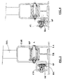
- Figure 2 shows a sectional front view of the carriage CAR, on which a load-bearing wheel RP can be seen, with axle A fixed at the two sides of the carriage.
- the wheel RP runs with guides on a double-T beams TR.
- the carriage CAR can have two or more load-bearing wheels RP.
- the carriage CAR is essentially in the shape of an overturned U, which in a preferred embodiment surrounds the beams TR laterally, acting as protection against dangerous external access and as a dust guard.
- TEL Fixed on the upper side of the carriage is a frame TEL, to support the materials to be stored.
- the projection SP is perpendicular to the side of the carriage, in a horizontal position. It could also be slightly tilted.
- the external support SE is fixed to the floor, to the supporting surface of the beam, for example welded to a metal plate LA on which the beam TR is also supported, and extends laterally to the beam, essentially for the entire length thereof, and houses a series of small wheels RA.
- a horizontal covering CO is carried out on the external support SE, which extends over the small wheels RA.
- the covering can be fixed with screws, or can consist of an extension of the support SE. The purpose thereof is to protect from dangerous accidental external access and to guard the small wheels against the deposit of glass dust or other materials.
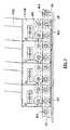
- Figure 3 shows a side view of a series of carriages CAR positioned in line on a beam TR on which they can run.
- the L-shaped external projection SP, two load bearing wheels RP and a frame TEL can be seen.
- the series of small wheels RA fixed to the external support SE are also visible.
- the load bearing wheels RP run on the beam, while the external projection SP always engages on at least two consecutive small wheels RA, which stabilize sliding of the carriage.
- the distance between the small wheels RA is preferably equal to or less than the distance between the two load bearing wheels RP of a carriage.
- the projection SP can also comprise two lateral wings AL, the purpose of which is to guide the small wheels RA, increasing the sliding stability.
- the small wheels RA are fixed on one side of the carriage towards the outside, and engage against the projection SP carried out on top of the external support SE.
- the projection SP in this case is above the small wheels RA, and also acts as horizontal covering.
- the number of small wheels RA for each carriage can be any, although two are preferred.
- the external support SE with relative small wheels RA and projection SP can be produced indifferently on the external or internal side of the carriage with respect to the storage system.
- the carriage can be fitted on beams with a different cross section, for example a square or rectangular cross section TRQ, as shown in Figure 5, or a flat cross section TP, as shown in Figure 6.
- a different cross section for example a square or rectangular cross section TRQ, as shown in Figure 5, or a flat cross section TP, as shown in Figure 6.
- the storage system can have frames that are not only parallel, but also with various tilt, for example a series of pairs of frames alternately tilted in opposite directions, each pair preferably fixed on the same pair of carriages.
Landscapes
- Engineering & Computer Science (AREA)
- Mechanical Engineering (AREA)
- Warehouses Or Storage Devices (AREA)
Applications Claiming Priority (2)
| Application Number | Priority Date | Filing Date | Title |
|---|---|---|---|
| ITMI20032074 ITMI20032074A1 (it) | 2003-10-23 | 2003-10-23 | Sistema di scorrimento per telai di un magazzino di stoccaggio a telai mobili su carrelli, e relativo magazzino. |
| ITMI20032074 | 2003-10-23 |
Publications (1)
| Publication Number | Publication Date |
|---|---|
| EP1526098A1 true EP1526098A1 (fr) | 2005-04-27 |
Family
ID=34385820
Family Applications (1)
| Application Number | Title | Priority Date | Filing Date |
|---|---|---|---|
| EP04105247A Withdrawn EP1526098A1 (fr) | 2003-10-23 | 2004-10-22 | Système coulissant pour des cadres d'un système de stockage, mobiles l'un à l'autre, et système coulissant correspondant |
Country Status (2)
| Country | Link |
|---|---|
| EP (1) | EP1526098A1 (fr) |
| IT (1) | ITMI20032074A1 (fr) |
Cited By (2)
| Publication number | Priority date | Publication date | Assignee | Title |
|---|---|---|---|---|
| EP3279119A1 (fr) * | 2016-08-05 | 2018-02-07 | Emmesse Societa' a Responsabilita' Limitata Semplificata | Unite de stockage pour des materiaux stratiformes |
| WO2019219936A1 (fr) * | 2018-05-17 | 2019-11-21 | Hegla Gmbh & Co. Kg | Dispositif de stockage destiné à stocker des plaques de verre, de préférence des plaques de verre feuilleté ou des plaques de verre de sécurité trempé |
Citations (3)
| Publication number | Priority date | Publication date | Assignee | Title |
|---|---|---|---|---|
| US3744184A (en) * | 1970-07-02 | 1973-07-10 | Toijalan Terasvalmiste Ky Velj | Shiftable packet mould partitions |
| EP0588394A1 (fr) * | 1992-09-18 | 1994-03-23 | Antonio Piazza | Magasin de stockage à châssis mobiles |
| EP0911283A2 (fr) * | 1997-10-27 | 1999-04-28 | Asahi Glass Company Ltd. | Dispositif d'alimentation d'articles en forme de plaque |
-
2003
- 2003-10-23 IT ITMI20032074 patent/ITMI20032074A1/it unknown
-
2004
- 2004-10-22 EP EP04105247A patent/EP1526098A1/fr not_active Withdrawn
Patent Citations (3)
| Publication number | Priority date | Publication date | Assignee | Title |
|---|---|---|---|---|
| US3744184A (en) * | 1970-07-02 | 1973-07-10 | Toijalan Terasvalmiste Ky Velj | Shiftable packet mould partitions |
| EP0588394A1 (fr) * | 1992-09-18 | 1994-03-23 | Antonio Piazza | Magasin de stockage à châssis mobiles |
| EP0911283A2 (fr) * | 1997-10-27 | 1999-04-28 | Asahi Glass Company Ltd. | Dispositif d'alimentation d'articles en forme de plaque |
Cited By (3)
| Publication number | Priority date | Publication date | Assignee | Title |
|---|---|---|---|---|
| EP3279119A1 (fr) * | 2016-08-05 | 2018-02-07 | Emmesse Societa' a Responsabilita' Limitata Semplificata | Unite de stockage pour des materiaux stratiformes |
| WO2019219936A1 (fr) * | 2018-05-17 | 2019-11-21 | Hegla Gmbh & Co. Kg | Dispositif de stockage destiné à stocker des plaques de verre, de préférence des plaques de verre feuilleté ou des plaques de verre de sécurité trempé |
| US12012296B2 (en) | 2018-05-17 | 2024-06-18 | Hegla Gmbh & Co. Kg | Storage device for storing glass panes, preferably laminated glass panes or tempered glass panes |
Also Published As
| Publication number | Publication date |
|---|---|
| ITMI20032074A1 (it) | 2005-04-24 |
Similar Documents
| Publication | Publication Date | Title |
|---|---|---|
| US5419444A (en) | Low profile push-back rack assembly | |
| EP0726724B1 (fr) | Systeme de rangement de chariots par retro-poussage | |
| US3850111A (en) | Vehicle mounted plate having guide rollers | |
| CA2484882A1 (fr) | Systeme d'entreposage de chariots par refoulement | |
| US20080203706A1 (en) | Drawer type storage cart | |
| EP1526098A1 (fr) | Système coulissant pour des cadres d'un système de stockage, mobiles l'un à l'autre, et système coulissant correspondant | |
| US11753285B2 (en) | Device for parking vehicles | |
| US4043463A (en) | Material storage frame support and vehicle guide structure | |
| US9440830B2 (en) | Personnel lift vehicle | |
| CA2025914A1 (fr) | Socle de faible hauteur pour installation de manutention et de stockage | |
| CN113336140B (zh) | 一种工业车辆移动称重系统 | |
| KR100870032B1 (ko) | 크레인 | |
| CN213230121U (zh) | 一种新型h型钢导向机构 | |
| CN209906293U (zh) | 一种叉车式igv车辆 | |
| CN219258471U (zh) | 一种用于智能仓库的穿梭式货架系统 | |
| CN217808574U (zh) | 物料升降交换结构 | |
| JP2683571B2 (ja) | 立体倉庫用搬送台車におけるガイド装置と給電装置の取付装置 | |
| JP6854200B2 (ja) | フォーク式機械駐車装置 | |
| CN222248657U (zh) | 货架及仓储系统 | |
| EP0925976A2 (fr) | Guide pour couverture mobile et couverture pourvue d'un tel guide | |
| US20080217109A1 (en) | Bearing assembly for lift chain rollers in a multiple lift mast for high-lift fork trucks | |
| CN210127621U (zh) | 一种装配式建筑外挂平台 | |
| CN220951065U (zh) | 一种具有平衡支撑架的可移动式堆垛机 | |
| JP2000043730A (ja) | プッシュバック収納台車装置 | |
| JP2001171807A (ja) | サイドフォークリフトを用いた棚設備 |
Legal Events
| Date | Code | Title | Description |
|---|---|---|---|
| PUAI | Public reference made under article 153(3) epc to a published international application that has entered the european phase |
Free format text: ORIGINAL CODE: 0009012 |
|
| AK | Designated contracting states |
Kind code of ref document: A1 Designated state(s): AT BE BG CH CY CZ DE DK EE ES FI FR GB GR HU IE IT LI LU MC NL PL PT RO SE SI SK TR |
|
| AX | Request for extension of the european patent |
Extension state: AL HR LT LV MK |
|
| AKX | Designation fees paid | ||
| REG | Reference to a national code |
Ref country code: DE Ref legal event code: 8566 |
|
| STAA | Information on the status of an ep patent application or granted ep patent |
Free format text: STATUS: THE APPLICATION IS DEEMED TO BE WITHDRAWN |
|
| 18D | Application deemed to be withdrawn |
Effective date: 20051028 |