EP1526228A1 - Gestell der Fernmeldetechnik - Google Patents
Gestell der Fernmeldetechnik Download PDFInfo
- Publication number
- EP1526228A1 EP1526228A1 EP03024316A EP03024316A EP1526228A1 EP 1526228 A1 EP1526228 A1 EP 1526228A1 EP 03024316 A EP03024316 A EP 03024316A EP 03024316 A EP03024316 A EP 03024316A EP 1526228 A1 EP1526228 A1 EP 1526228A1
- Authority
- EP
- European Patent Office
- Prior art keywords
- cabinet
- modules
- equipment
- module
- telecommunication
- Prior art date
- Legal status (The legal status is an assumption and is not a legal conclusion. Google has not performed a legal analysis and makes no representation as to the accuracy of the status listed.)
- Withdrawn
Links
- 238000001816 cooling Methods 0.000 description 5
- 238000013475 authorization Methods 0.000 description 1
- 239000002184 metal Substances 0.000 description 1
- 238000000034 method Methods 0.000 description 1
- 238000007789 sealing Methods 0.000 description 1
Images

Classifications
-
- E—FIXED CONSTRUCTIONS
- E04—BUILDING
- E04H—BUILDINGS OR LIKE STRUCTURES FOR PARTICULAR PURPOSES; SWIMMING OR SPLASH BATHS OR POOLS; MASTS; FENCING; TENTS OR CANOPIES, IN GENERAL
- E04H1/00—Buildings or groups of buildings for dwelling or office purposes; General layout, e.g. modular co-ordination or staggered storeys
- E04H1/12—Small buildings or other erections for limited occupation, erected in the open air or arranged in buildings, e.g. kiosks, waiting shelters for bus stops or for filling stations, roofs for railway platforms, watchmen's huts or dressing cubicles
- E04H1/1205—Small buildings erected in the open air
- E04H1/1238—Shelters for engines, e.g. electrical meter housings
Definitions
- the present invention relates to a cabinet in accordance with the preamble of claim 1.
- Telecommunication equipment is normally held in cabinets, which give shelter from wind, rain, snow, etc, and keep people without authorisation away. Not only telecommunication equipment is held in such cabinets, but also other equipment which is related to the telecommunication equipment, such as cooling equipment, distribution equipment, battery back-up equipment and power supply equipment, which from obvious reasons are required for the function of the telecommunication equipment.
- the equipment is normally arranged in racks of fixed dimensions within the cabinets and thus need to share the existing space defined by these racks.
- a solution to this problem is to arrange yet a cabinet next to the first cabinet, and in which the upgrading/replacing/additional equipment is placed.
- horizontal cabinet clustering is expensive and takes up a great deal of space, which can be disadvantageous, e.g. when the cabinet is located in densely built-up areas, and furthermore requires that the ground, where the cabinet is to be mounted, is extensively prepared.
- An object of the present invention is to provide a cabinet which is independent of equipment upgrade and/or equipment replacement.
- Yet an object of the present invention is to provide a cabinet which easily can be assembled at any location.
- the cabinet modules are mutually connectable on top of each other, the cabinet modules can be stacked in a vertical direction.
- cabinets with small cross-sections can be designed, and that horizontally extended, space requiring cabinet clusters are avoided.
- the modularity also promote allocation of telecommunication related equipment, such as telecommunication equipment, cooling equipment, distribution equipment, battery back-up equipment and power supply equipment to specific cabinet modules. Due to this equipment allocation possibility, equipment supplier independence, equipment replacement independence as well as upgrade independence are achieved. For example, a specific cabinet module can be prepared, in advance, with appropriate equipment before replacing the "old" cabinet module on site. In addition, the modularity also makes it possible to change the configuration of the cabinet on site at a very late stage of the cabinet assembly process.
- said cabinet modules comprise a common mechanical interface for mutual connection of said cabinet modules.
- the cabinet modules can be mounted independently of their vertical size.
- said mechanical interface comprises means for removably connecting two adjacent cabinet modules.
- said mechanical interface comprises means for removably connecting two adjacent cabinet modules.
- said cabinet modules have substantially flat side surfaces with bevelled comers.
- the surfaces of the cabinet can easily be used for, e.g. advertising messages or other type of public information. Since the cabinet is stackable in a vertical direction and is provided with the flat side surfaces, deliberate damages to the cabinet is made more difficult.
- said cabinet modules can be of different size. Hereby is further flexibility achieved.
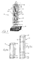
- Fig. 1a-c show a cabinet 10 in accordance with a preferred embodiment of the present invention and is mounted on the ground, on e.g. a concrete slab.
- the cabinet 10 is adapted to hold telecommunication equipment as well as other equipment which is necessary for the function of the telecommunication equipment, such as cooling, distribution, battery back-up and power supply equipment.
- the cabinet 10 comprises, in this embodiment, six cabinet modules made of sheet metal (which are more thoroughly explained in connection with fig. 3), which are stacked on top of each other, so as to form the cabinet.
- fig. 1a covers 12 belonging to a specific cabinet module have been partly removed, wherein the equipment contained in each cabinet module is exposed.
- An advertising sign 14 is mounted on top of the cabinet.
- the cabinet is suitable for both indoor and outdoor use.
- an antenna 15 is arranged on top of the cabinet, but it is also possible to arrange other devices on top of the cabinet, such as clocks, illuminated advertising devices, television displays, etc, especially if the cabinet is to be placed in an urban environment.
- the cabinet 10 is instead situated on a railway station platform, where it also functions as a post for a roof structure.
- FIG. 3 shows an exploded view of the six cabinet modules 16-26 of fig. 1-2. These modules are stacked on top of each other and thus form a vertically erected cabinet.
- Each cabinet module 16-26 has a substantially square cross-section and comprises an upper surface 28, a lower surface 30 and four side surfaces 32 (of which only two are shown of clarity reasons). Comers 33 which connect two adjacent side surfaces are somewhat bevelled or rounded, which facilitate pasting of advertising posters up on the side surfaces 32 when the cabinet is used in, e.g. an urban environment.
- the cabinet modules 16-26 are provided with a mechanical interface 34 in the form of mutually aligned bore holes 34 disposed in the upper and the lower surfaces of each cabinet module, respectively, in combination with screw joints 34 to firmly connect the cabinet modules 16-26, and to provide a removable connection between the cabinet modules.
- This mechanical interface is of clarity reasons only depicted on the lower surface 30 of the cabinet module 22 and on the upper surface 28 of the cabinet module 20, but the other cabinet modules are of course also provided with a corresponding mechanical interface.
- Fig. 4a-b show two further embodiments of vertically stacked cabinet modules. The configuration depends on application, and other configurations than those depicted are conceivable, e.g. more or less cabinet modules.
- a L-module i.e. a cabinet module of height L
- a L/2-module i.e. a cabinet module of height L
- a L/4-module i.e. a cabinet module of height L
- a L/4-module i.e. a cabinet module of height L
- a L/4-module i.e. a cabinet module of height L
- a L/4-module i.e. a cabinet module of height L
- L/4-module i.e. a cabinet module of height L
- L/4-module i.e. a cabinet module of height L
- L/4-module i.e. a cabinet module of height L
- a L/4-module i.e. a cabinet module of height L
- a L/4-module i.e. a cabinet module of height L
- a L/4-module i.e. a cabinet module of height L
- a L/4-module i
- cabinet modules 16-26 are provided with appropriate through-holes to facilitate cabling between adjacent cabinet modules and provide space for ventilating ducts, etc.
- the present invention is not restricted to the four different cabinet modules shown above, but the number of different cabinet modules can be extended to, e.g. a 3/2L-module, a 2L-module, and a L/6-module, and so on.
Landscapes
- Engineering & Computer Science (AREA)
- Architecture (AREA)
- Civil Engineering (AREA)
- Structural Engineering (AREA)
- Casings For Electric Apparatus (AREA)
Priority Applications (1)
| Application Number | Priority Date | Filing Date | Title |
|---|---|---|---|
| EP03024316A EP1526228A1 (de) | 2003-10-24 | 2003-10-24 | Gestell der Fernmeldetechnik |
Applications Claiming Priority (1)
| Application Number | Priority Date | Filing Date | Title |
|---|---|---|---|
| EP03024316A EP1526228A1 (de) | 2003-10-24 | 2003-10-24 | Gestell der Fernmeldetechnik |
Publications (1)
| Publication Number | Publication Date |
|---|---|
| EP1526228A1 true EP1526228A1 (de) | 2005-04-27 |
Family
ID=34384613
Family Applications (1)
| Application Number | Title | Priority Date | Filing Date |
|---|---|---|---|
| EP03024316A Withdrawn EP1526228A1 (de) | 2003-10-24 | 2003-10-24 | Gestell der Fernmeldetechnik |
Country Status (1)
| Country | Link |
|---|---|
| EP (1) | EP1526228A1 (de) |
Citations (3)
| Publication number | Priority date | Publication date | Assignee | Title |
|---|---|---|---|---|
| US5810459A (en) * | 1996-02-26 | 1998-09-22 | Unisys Corporation | Stackable modular cabinet |
| US6297958B1 (en) * | 2000-05-26 | 2001-10-02 | General Bandwidth Inc. | System and method for housing telecommunications equipment |
| US20020136042A1 (en) * | 2000-03-29 | 2002-09-26 | David Layden | System for detecting defective battery packs |
-
2003
- 2003-10-24 EP EP03024316A patent/EP1526228A1/de not_active Withdrawn
Patent Citations (3)
| Publication number | Priority date | Publication date | Assignee | Title |
|---|---|---|---|---|
| US5810459A (en) * | 1996-02-26 | 1998-09-22 | Unisys Corporation | Stackable modular cabinet |
| US20020136042A1 (en) * | 2000-03-29 | 2002-09-26 | David Layden | System for detecting defective battery packs |
| US6297958B1 (en) * | 2000-05-26 | 2001-10-02 | General Bandwidth Inc. | System and method for housing telecommunications equipment |
Similar Documents
| Publication | Publication Date | Title |
|---|---|---|
| US8839569B2 (en) | Truly modular building datacenter facility | |
| US9603281B2 (en) | Truly modular building datacenter facility | |
| US20140055914A1 (en) | Integration of a service cabinet into a street furniture | |
| US20210367331A1 (en) | Multi-Purpose Smart Tower | |
| CA2467300A1 (en) | Modular in-wall medical services outlet system | |
| US9133633B2 (en) | Modular insulated scaffold wall system | |
| CN100491674C (zh) | 城市变电中心 | |
| EP1526228A1 (de) | Gestell der Fernmeldetechnik | |
| US20090213531A1 (en) | Transformer substation | |
| CN213420886U (zh) | 一种新型卡槽拓展智慧灯杆 | |
| CN210152342U (zh) | 一种扩展型的数据中心 | |
| DE19637436C2 (de) | Gehäuse zur Aufnahme von nachrichtentechnischen Baugruppen | |
| US12562469B2 (en) | Vertically stacked, integratable, multipurpose platform configurable as wireless base stations | |
| CN201403091Y (zh) | 一体化集成通信基站 | |
| CN218176145U (zh) | 一种蜂巢型装配式模块化房屋 | |
| AU603633B2 (en) | A method and system for preparing an exhibition space | |
| CN210896266U (zh) | 一种多功能路牌 | |
| CN110107122B (zh) | 一种扩展型的数据中心 | |
| EP4402749A2 (de) | Vertikal gestapelte, integrierbare mehrzweckplattform, die als drahtlose basisstationen konfigurierbar ist | |
| CN223786699U (zh) | 一种展示花箱罩及花箱 | |
| CN223018344U (zh) | 建设工程管理用环保降噪装置 | |
| CN211792573U (zh) | 一种拼接式通信用综合集装架 | |
| CN217215786U (zh) | 一种高强度拼装式电缆桥架 | |
| CN215376802U (zh) | 一种模块化无线拼装显示屏 | |
| CN215679988U (zh) | 一种旅游景区用的环保标识标牌 |
Legal Events
| Date | Code | Title | Description |
|---|---|---|---|
| PUAI | Public reference made under article 153(3) epc to a published international application that has entered the european phase |
Free format text: ORIGINAL CODE: 0009012 |
|
| AK | Designated contracting states |
Kind code of ref document: A1 Designated state(s): AT BE BG CH CY CZ DE DK EE ES FI FR GB GR HU IE IT LI LU MC NL PT RO SE SI SK TR |
|
| AX | Request for extension of the european patent |
Extension state: AL LT LV MK |
|
| AKX | Designation fees paid | ||
| REG | Reference to a national code |
Ref country code: DE Ref legal event code: 8566 |
|
| STAA | Information on the status of an ep patent application or granted ep patent |
Free format text: STATUS: THE APPLICATION IS DEEMED TO BE WITHDRAWN |
|
| 18D | Application deemed to be withdrawn |
Effective date: 20051028 |