EP1526321A1 - Werkzeug zum Erzeugen einer Öffnung in einer Fluidleitung - Google Patents
Werkzeug zum Erzeugen einer Öffnung in einer Fluidleitung Download PDFInfo
- Publication number
- EP1526321A1 EP1526321A1 EP04104943A EP04104943A EP1526321A1 EP 1526321 A1 EP1526321 A1 EP 1526321A1 EP 04104943 A EP04104943 A EP 04104943A EP 04104943 A EP04104943 A EP 04104943A EP 1526321 A1 EP1526321 A1 EP 1526321A1
- Authority
- EP
- European Patent Office
- Prior art keywords
- punch
- fluid line
- tool according
- lever
- wall
- Prior art date
- Legal status (The legal status is an assumption and is not a legal conclusion. Google has not performed a legal analysis and makes no representation as to the accuracy of the status listed.)
- Granted
Links
- 239000012530 fluid Substances 0.000 title claims abstract description 29
- XLYOFNOQVPJJNP-UHFFFAOYSA-N water Substances O XLYOFNOQVPJJNP-UHFFFAOYSA-N 0.000 claims abstract description 6
- 239000002184 metal Substances 0.000 claims abstract description 5
- 230000000149 penetrating effect Effects 0.000 claims abstract description 3
- 229910000760 Hardened steel Inorganic materials 0.000 claims description 2
- 239000000919 ceramic Substances 0.000 claims description 2
- 238000005096 rolling process Methods 0.000 claims description 2
- 230000005540 biological transmission Effects 0.000 claims 1
- 238000005553 drilling Methods 0.000 description 4
- 230000008719 thickening Effects 0.000 description 2
- 239000003795 chemical substances by application Substances 0.000 description 1
- 238000003780 insertion Methods 0.000 description 1
- 230000037431 insertion Effects 0.000 description 1
- 230000002262 irrigation Effects 0.000 description 1
- 238000003973 irrigation Methods 0.000 description 1
- 238000004091 panning Methods 0.000 description 1
- 230000035515 penetration Effects 0.000 description 1
- 238000005476 soldering Methods 0.000 description 1
- 238000003466 welding Methods 0.000 description 1
Images


Classifications
-
- F—MECHANICAL ENGINEERING; LIGHTING; HEATING; WEAPONS; BLASTING
- F16—ENGINEERING ELEMENTS AND UNITS; GENERAL MEASURES FOR PRODUCING AND MAINTAINING EFFECTIVE FUNCTIONING OF MACHINES OR INSTALLATIONS; THERMAL INSULATION IN GENERAL
- F16L—PIPES; JOINTS OR FITTINGS FOR PIPES; SUPPORTS FOR PIPES, CABLES OR PROTECTIVE TUBING; MEANS FOR THERMAL INSULATION IN GENERAL
- F16L41/00—Branching pipes; Joining pipes to walls
- F16L41/04—Tapping pipe walls, i.e. making connections through the walls of pipes while they are carrying fluids; Fittings therefor
- F16L41/06—Tapping pipe walls, i.e. making connections through the walls of pipes while they are carrying fluids; Fittings therefor making use of attaching means embracing the pipe
- F16L41/065—Tapping pipe walls, i.e. making connections through the walls of pipes while they are carrying fluids; Fittings therefor making use of attaching means embracing the pipe without removal of material
-
- B—PERFORMING OPERATIONS; TRANSPORTING
- B21—MECHANICAL METAL-WORKING WITHOUT ESSENTIALLY REMOVING MATERIAL; PUNCHING METAL
- B21D—WORKING OR PROCESSING OF SHEET METAL OR METAL TUBES, RODS OR PROFILES WITHOUT ESSENTIALLY REMOVING MATERIAL; PUNCHING METAL
- B21D28/00—Shaping by press-cutting; Perforating
- B21D28/24—Perforating, i.e. punching holes
- B21D28/28—Perforating, i.e. punching holes in tubes or other hollow bodies
Definitions
- the invention relates to a tool for producing an opening in the wall a fluid line, in particular a metal tube for pressurized water, with a Support for the fluid line, with a punch for penetrating the Wall, with a hand-operated lever for driving the punch.
- Such a tool can be fluid lines with an opening provided to thereby a branch for attaching a Branch line or a nozzle to create.
- Such tools will be mainly used for creating openings in plastic pipes used for the administration of water under low pressure, for example Serve irrigation systems.
- a hand-operated lever such Make an opening in the wall. If not equal with sufficient strength is worked to penetrate the wall, it is necessary with that is re-scheduled. In this case, it may happen that the fluid line in the recording slips and thus adjacent to the later opening Damage to the walls occur. This can lead to unwanted leaks to lead.
- the problem underlying the invention is to provide a tool for generating indicate an opening in the wall of a fluid line with which the Opening safely and reliably generate at a given location.
- the recording is in a on a base formed clampable jaw.
- the fluid line can be safe be clamped between the jaw and the base. It can also an operable by means of a handle articulated lever for clamping the Jaw be provided to the base.
- a Adjustment means for adjusting the fixing force can be such a simple and reliable operation for clamping the fluid line in the receptacle after Achieve the kind of grip pliers.
- the Punch is coupled by means of a gear with the lever.
- the Gear can be, for example, a cam mechanism.
- a continuing education draws characterized by the fact that the cam gear mounted eccentrically Cam disc having a cam track, which with a cam for driving the punch cooperates.
- the cam has a rotatable for rolling on the cam track mounted ball or roller.
- This ball or Roller can be made of ceramic or hardened steel.
- the punch can also slidably in a recording be arranged housing.
- a large stroke of the punch can be added at the same time precise guidance for creating a high quality opening in the Achieve wall of the fluid line.
- Another embodiment of the invention is characterized in that the Punch a front first area with a first angle and a first area adjacent second area with a smaller second angle having.
- This first area causes denting and grooving the wall in a relatively small area. This will be relative transfer large forces. After the first area has penetrated into the wall is, the opening in the wall increases more and more. With this no undesirable large forces occur, the opening angle in the second area with a larger diameter relatively small. This causes a relatively large insertion of the punch in the opening only one relatively small change in the diameter of the opening. This is with relatively little effort possible.
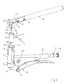
- Fig. 1 shows a tool for creating an opening in the wall of a Fluid line with the features of the invention.
- the tool has a housing 10 on, which is rigidly connected to a lever 11.
- the lever 11 can with the Housing 10, for example screwed, riveted or integral with this be educated.
- an eccentric 13 In an upper portion of the housing 10 is pivotally around an axis 12 an eccentric 13, which has a cam track 14th having.
- the eccentric disc 13 is remote from the housing 10 at its Side connected by means of two bolts 15 with a lever 16.
- a jaw 17 is arranged at the end facing away from the axis 12 of the housing 10 at the end facing away from the axis 12 of the housing 10 at the end facing away from the axis 12 of the housing 10 at the end facing away from the axis 12 of the housing 10 at the end facing away from the axis 12 of the housing 10 at the end facing away from the axis 12 of the housing 10 is this facing a jaw 17 is arranged.
- the housing 10 and the Jaw 17 have on their facing surfaces each one partially cylindrical recess, which together form a receptacle 18 for Take up receiving a fluid line.
- the jaw 17 is rigid with a hinge lever 19 is connected.
- the rigid connection can be, for example by screwing, soldering or welding or by means of a be ensured one-piece design.
- the articulated lever 19 is by means of a first axis 20 pivotally mounted on the lever 11 and by means of a second axis 21st also pivotally mounted on a handle 22.
- the handle 22 is again by means of a lever not shown in the figure with a Knurled screw 24 connected in a nut 23 from the housing 10th remote end of the lever 11 is screwed.
- Fig. 2 shows an exploded view of the tool of Fig. 1. Like elements bear the same reference numbers.
- the Eccentric disc 13 a concentric with the cam track 14 recess 25.
- a cylindrical bore 26 of the housing 10 is beyond a Guide 27 arranged for a punch 28.
- the housing 10 has over it In addition, two slots 29 for the eccentric disc 13.
- the punch 28 is arranged in a bore of the guide 27.
- the Guide 27 has an approximately cylindrical shape and has at her the Eccentric disc 13 side facing one of these associated slit 30.
- the eccentric disc 13 In the assembled state, the eccentric disc 13 in the region of the slit 30th arranged, wherein a roller 31 is arranged in the recess 25 and by means of a Bolzens 32 is fixed in a bore 33 of the guide 27.
- a screw 34 is used for attaching the punch 28 to the guide 27.
- the screw 34 has her the roller 31 side facing a hexagon socket 35.
- Fig. 3 shows the eccentric disc 13 in an enlarged view.
- the Eccentric disc has two bolts 15 associated holes 36 and a the axis 12 associated bore 37.
- the recess 25 and the cam track 14 concentric with each other and arranged eccentrically to the bore 37.
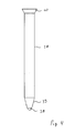
- Fig. 4 shows the punch 28 in an enlarged view.
- the Punch 28 has at its tip a first portion 38 and a this adjacent second area 39 on.
- the first region 38 is relatively blunt, while the second region 39 is sharper, that is, has a smaller angle than the first area 38.
- the Areas 38, 39 facing away from the punch 28 has a thickening 40, by means of which one hand falling out of the punch 28 from the guide 27th is prevented and on the other hand serves as a repository for the cam 34.
- Diameter of the fluid line can be the angle of attack of the articulated lever 19 in a closed state of the tool, in which the handle 22 on the Lever 11 rests by screwing the thumbscrew 24 into the nut 23rd adjust.
- the Punch 28 by pivoting down the lever 16 from a to the Lever 11 almost rectangular position in a nearly parallel to the lever 11 Position driven into the wall of the fluid line.
- the eccentric causes Arrangement of the cam track 14 to the axis 12, that at the beginning of generating the Opening in the wall of the fluid line in the state in which the lever 16 is arranged almost perpendicular to the lever 11, between the support point the cam track 14 and the axle 12 only a relatively small lever arm is trained.
Landscapes
- Engineering & Computer Science (AREA)
- General Engineering & Computer Science (AREA)
- Mechanical Engineering (AREA)
- Perforating, Stamping-Out Or Severing By Means Other Than Cutting (AREA)
- Drilling Tools (AREA)
- Punching Or Piercing (AREA)
Abstract
Description
- Fig. 1
- eine perspektivische Darstellung eines Werkzeugs mit den Erfindungsmerkmalen,
- Fig. 2
- eine Explosionsdarstellung des Werkzeugs von Fig. 1,
- Fig. 3
- eine Draufsicht auf eine Exzenterscheibe des Werkzeugs mit den Erfindungsmerkmalen, und
- Fig. 4
- einen Lochstempel des Werkzeugs mit den Erfindungsmerkmalen.
- 10
- Gehäuse
- 11
- Hebel
- 12
- Achse
- 13
- Exzenterscheibe
- 14
- Nockenbahn
- 15
- Bolzen
- 16
- Hebel
- 17
- Klemmbacke
- 18
- Aufnahme
- 19
- Gelenkhebel
- 20
- Achse
- 21
- Achse
- 22
- Griffstück
- 23
- Mutter
- 24
- Rändelschraube
- 25
- Aussparung
- 26
- Bohrung
- 27
- Führung
- 28
- Lochstempel
- 29
- Schlitz
- 30
- Schlitzung
- 31
- Rolle
- 32
- Bolzen
- 33
- Bohrung
- 34
- Schraube
- 35
- Kugel
- 36
- Bohrung
- 37
- Bohrung
- 38
- erster Bereich
- 39
- zweiter Bereich
- 40
- Verdickung
Claims (10)
- Werkzeug zum Erzeugen einer Öffnung in der Wandung einer Fluidleitung, insbesondere eines Metallrohres für Druckwasser, mit einer Aufnahme (18) für die Fluidleitung, mit einem Lochstempel (28) zum Durchdringen der Wandung, und mit einem handbetätigbaren Hebel (16) zum Antreiben des Lochstempels (28), gekennzeichnet durch Fixiermittel (17, 19, 22) zum Fixieren der Fluidleitung in der Aufnahme (18).
- Werkzeug nach Anspruch 1, dadurch gekennzeichnet, daß die Aufnahme (18) in einer an eine Basis klemmbaren Klemmbacke (17) ausgebildet ist.
- Werkzeug nach Anspruch 2, gekennzeichnet durch einen mittels eines Griffstückes (22) betätigbaren Gelenkhebel (19) zum Klemmen der Klemmbacke (17) an die Basis.
- Werkzeug nach einem der vorhergehenden Ansprüche, gekennzeichnet durch Verstellmittel (23, 24) zum Verstellen der Fixierkraft.
- Werkzeug nach einem der vorhergehenden Ansprüche, dadurch gekennzeichnet, daß der Lochstempel (28) mittels eines Getriebes (14, 34) mit dem Hebel (16) gekoppelt ist, insbesondere mittels eines Kurvengetriebes (14, 34).
- Werkzeug nach Anspruch 5, dadurch gekennzeichnet, daß das Kurvengetriebe eine exzentrisch gelagerte Kurvenscheibe (13) mit einer Nockenbahn (14) aufweist, die mit einer Nocke (31) zum Antreiben des Lochstempels (28) zusammenwirkt.
- Werkzeug nach Anspruch 6, dadurch gekennzeichnet, daß die Nocke (34) eine drehbar zum Abrollen auf der Nockenbahn (14) gelagerte Kugel oder Rolle (31), insbesondere aus Keramik oder gehärtetem Stahl, aufweist.
- Werkzeug nach einem der vorhergehenden Ansprüche, dadurch gekennzeichnet, daß der Lochstempel (28) verschiebbar in einem die Aufnahme (18) aufweisenden Gehäuse (10) angeordnet ist.
- Werkzeug nach einem der vorhergehenden Ansprüche, gekennzeichnet durch eine Führung (26, 27) für den Lochstempel (28).
- Werkzeug nach einem der vorhergehenden Ansprüche, dadurch gekennzeichnet, daß der Lochstempel (28) einen vorderen ersten Bereich (38) mit einem ersten Winkel und einen dem ersten Bereich benachbarten zweiten Bereich (39) mit einem kleineren zweiten Winkel aufweist.
Applications Claiming Priority (4)
| Application Number | Priority Date | Filing Date | Title |
|---|---|---|---|
| DE10349214 | 2003-10-20 | ||
| DE10349214 | 2003-10-20 | ||
| DE102004003015A DE102004003015A1 (de) | 2003-10-20 | 2004-01-20 | Werkzeug zum Erzeugen einer Öffnung in einer Fluidleitung |
| DE102004003015 | 2004-01-20 |
Publications (2)
| Publication Number | Publication Date |
|---|---|
| EP1526321A1 true EP1526321A1 (de) | 2005-04-27 |
| EP1526321B1 EP1526321B1 (de) | 2007-02-28 |
Family
ID=34395064
Family Applications (1)
| Application Number | Title | Priority Date | Filing Date |
|---|---|---|---|
| EP04104943A Expired - Lifetime EP1526321B1 (de) | 2003-10-20 | 2004-10-08 | Werkzeug zum Erzeugen einer Öffnung in einer Fluidleitung |
Country Status (3)
| Country | Link |
|---|---|
| EP (1) | EP1526321B1 (de) |
| AT (1) | ATE355487T1 (de) |
| DE (1) | DE502004003015D1 (de) |
Cited By (3)
| Publication number | Priority date | Publication date | Assignee | Title |
|---|---|---|---|---|
| ES2277744A1 (es) * | 2004-06-15 | 2007-07-16 | Mordechai Eldar | Herramientas de punzonado para manguera de riego de seccion plana. |
| CN103537527A (zh) * | 2012-07-13 | 2014-01-29 | 北汽福田汽车股份有限公司 | 一种钣金冲孔装置 |
| US9744581B2 (en) | 2013-10-24 | 2017-08-29 | Wubbers Llc | Hole punching pliers and method of using same |
Citations (3)
| Publication number | Priority date | Publication date | Assignee | Title |
|---|---|---|---|---|
| US3395724A (en) * | 1965-10-22 | 1968-08-06 | Union Carbide Corp | Piercing valve |
| US3939683A (en) * | 1974-11-28 | 1976-02-24 | Geffen Johannes Adrianus Van | Piercing tools |
| US6367362B1 (en) * | 1998-02-16 | 2002-04-09 | Ryobi North America, Inc. | Apparatus for punching steel studs |
-
2004
- 2004-10-08 EP EP04104943A patent/EP1526321B1/de not_active Expired - Lifetime
- 2004-10-08 DE DE502004003015T patent/DE502004003015D1/de not_active Expired - Lifetime
- 2004-10-08 AT AT04104943T patent/ATE355487T1/de active
Patent Citations (3)
| Publication number | Priority date | Publication date | Assignee | Title |
|---|---|---|---|---|
| US3395724A (en) * | 1965-10-22 | 1968-08-06 | Union Carbide Corp | Piercing valve |
| US3939683A (en) * | 1974-11-28 | 1976-02-24 | Geffen Johannes Adrianus Van | Piercing tools |
| US6367362B1 (en) * | 1998-02-16 | 2002-04-09 | Ryobi North America, Inc. | Apparatus for punching steel studs |
Cited By (5)
| Publication number | Priority date | Publication date | Assignee | Title |
|---|---|---|---|---|
| ES2277744A1 (es) * | 2004-06-15 | 2007-07-16 | Mordechai Eldar | Herramientas de punzonado para manguera de riego de seccion plana. |
| ES2277744B1 (es) * | 2004-06-15 | 2008-05-16 | Mordechai Eldar | Herramienta de punzonado para manguera de riego de seccion plana. |
| CN103537527A (zh) * | 2012-07-13 | 2014-01-29 | 北汽福田汽车股份有限公司 | 一种钣金冲孔装置 |
| CN103537527B (zh) * | 2012-07-13 | 2016-08-24 | 北汽福田汽车股份有限公司 | 一种手动钣金冲孔装置 |
| US9744581B2 (en) | 2013-10-24 | 2017-08-29 | Wubbers Llc | Hole punching pliers and method of using same |
Also Published As
| Publication number | Publication date |
|---|---|
| DE502004003015D1 (de) | 2007-04-12 |
| ATE355487T1 (de) | 2006-03-15 |
| EP1526321B1 (de) | 2007-02-28 |
Similar Documents
| Publication | Publication Date | Title |
|---|---|---|
| DE102008005472B3 (de) | Presszange | |
| DE19963097C1 (de) | Zange zum Verpressen eines Werkstücks | |
| EP1649981B1 (de) | Presszange | |
| EP3718185B1 (de) | Abisolierzange | |
| EP3718184B1 (de) | Klemmbacken für eine abisolierzange, sowie abisolierzange | |
| DE102005003617B3 (de) | Presszange zm Einpressen mehrerer Kerben auf dem Umfang eines Kontaktelementes | |
| EP3269509B1 (de) | Trapezlochzange | |
| WO2006027269A1 (de) | Wechselvorrichtung für spannköpfe mit mehreren spannbacken | |
| EP1319456B1 (de) | Kabelschneider | |
| DE3136406C2 (de) | ||
| EP0619153B1 (de) | Aufweitewerkzeug für hohle Werkstücke | |
| EP1526321B1 (de) | Werkzeug zum Erzeugen einer Öffnung in einer Fluidleitung | |
| DE4424493C2 (de) | Zangenartiges Werkzeug zum formschlüssigen Verbinden von Blechteilen | |
| DE19610899C1 (de) | Arbeitszange | |
| EP1157758B1 (de) | Vorrichtung zum Entfernen von Beulen aus Blech | |
| DE3120247A1 (de) | "bohrvorrichtung fuer eine motorbetriebene handbohrmaschine" | |
| EP3292931A1 (de) | Werkzeug, insbesondere für die spanabhebende werkstückbearbeitung | |
| DE102004003015A1 (de) | Werkzeug zum Erzeugen einer Öffnung in einer Fluidleitung | |
| EP2236233B1 (de) | Stichsäge | |
| DE102005028594B3 (de) | Zange, insbesondere Niet-, Ösen- oder Lochzange | |
| DE10110712C2 (de) | Austreibvorrichtung zum Herauslösen des Kegelschafts eines Werkzeugs aus einer Werkzeugaufnahme | |
| DE202007018107U1 (de) | Vorrichtung zum Öffnen von Nuten | |
| DE29920822U1 (de) | Bördelgerät zum Bördeln von Rohrenden | |
| DE10044874A1 (de) | Schlüsselzange | |
| DE19646159C2 (de) | Vorrichtung zum Stanzen von Öffnungen |
Legal Events
| Date | Code | Title | Description |
|---|---|---|---|
| PUAI | Public reference made under article 153(3) epc to a published international application that has entered the european phase |
Free format text: ORIGINAL CODE: 0009012 |
|
| AK | Designated contracting states |
Kind code of ref document: A1 Designated state(s): AT BE BG CH CY CZ DE DK EE ES FI FR GB GR HU IE IT LI LU MC NL PL PT RO SE SI SK TR |
|
| AX | Request for extension of the european patent |
Extension state: AL HR LT LV MK |
|
| 17P | Request for examination filed |
Effective date: 20051027 |
|
| AKX | Designation fees paid |
Designated state(s): AT BE BG CH CY CZ DE DK EE ES FI FR GB GR HU IE IT LI LU MC NL PL PT RO SE SI SK TR |
|
| GRAP | Despatch of communication of intention to grant a patent |
Free format text: ORIGINAL CODE: EPIDOSNIGR1 |
|
| GRAS | Grant fee paid |
Free format text: ORIGINAL CODE: EPIDOSNIGR3 |
|
| GRAA | (expected) grant |
Free format text: ORIGINAL CODE: 0009210 |
|
| AK | Designated contracting states |
Kind code of ref document: B1 Designated state(s): AT BE BG CH CY CZ DE DK EE ES FI FR GB GR HU IE IT LI LU MC NL PL PT RO SE SI SK TR |
|
| PG25 | Lapsed in a contracting state [announced via postgrant information from national office to epo] |
Ref country code: DK Free format text: LAPSE BECAUSE OF FAILURE TO SUBMIT A TRANSLATION OF THE DESCRIPTION OR TO PAY THE FEE WITHIN THE PRESCRIBED TIME-LIMIT Effective date: 20070228 Ref country code: FI Free format text: LAPSE BECAUSE OF FAILURE TO SUBMIT A TRANSLATION OF THE DESCRIPTION OR TO PAY THE FEE WITHIN THE PRESCRIBED TIME-LIMIT Effective date: 20070228 Ref country code: PL Free format text: LAPSE BECAUSE OF FAILURE TO SUBMIT A TRANSLATION OF THE DESCRIPTION OR TO PAY THE FEE WITHIN THE PRESCRIBED TIME-LIMIT Effective date: 20070228 Ref country code: IE Free format text: LAPSE BECAUSE OF FAILURE TO SUBMIT A TRANSLATION OF THE DESCRIPTION OR TO PAY THE FEE WITHIN THE PRESCRIBED TIME-LIMIT Effective date: 20070228 Ref country code: NL Free format text: LAPSE BECAUSE OF FAILURE TO SUBMIT A TRANSLATION OF THE DESCRIPTION OR TO PAY THE FEE WITHIN THE PRESCRIBED TIME-LIMIT Effective date: 20070228 Ref country code: SI Free format text: LAPSE BECAUSE OF FAILURE TO SUBMIT A TRANSLATION OF THE DESCRIPTION OR TO PAY THE FEE WITHIN THE PRESCRIBED TIME-LIMIT Effective date: 20070228 |
|
| REG | Reference to a national code |
Ref country code: GB Ref legal event code: FG4D Free format text: NOT ENGLISH |
|
| REG | Reference to a national code |
Ref country code: CH Ref legal event code: EP |
|
| REF | Corresponds to: |
Ref document number: 502004003015 Country of ref document: DE Date of ref document: 20070412 Kind code of ref document: P |
|
| REG | Reference to a national code |
Ref country code: IE Ref legal event code: FG4D Free format text: LANGUAGE OF EP DOCUMENT: GERMAN |
|
| PG25 | Lapsed in a contracting state [announced via postgrant information from national office to epo] |
Ref country code: BG Free format text: LAPSE BECAUSE OF FAILURE TO SUBMIT A TRANSLATION OF THE DESCRIPTION OR TO PAY THE FEE WITHIN THE PRESCRIBED TIME-LIMIT Effective date: 20070529 |
|
| PG25 | Lapsed in a contracting state [announced via postgrant information from national office to epo] |
Ref country code: SE Free format text: LAPSE BECAUSE OF FAILURE TO SUBMIT A TRANSLATION OF THE DESCRIPTION OR TO PAY THE FEE WITHIN THE PRESCRIBED TIME-LIMIT Effective date: 20070531 |
|
| PG25 | Lapsed in a contracting state [announced via postgrant information from national office to epo] |
Ref country code: ES Free format text: LAPSE BECAUSE OF FAILURE TO SUBMIT A TRANSLATION OF THE DESCRIPTION OR TO PAY THE FEE WITHIN THE PRESCRIBED TIME-LIMIT Effective date: 20070608 |
|
| GBT | Gb: translation of ep patent filed (gb section 77(6)(a)/1977) |
Effective date: 20070530 |
|
| PG25 | Lapsed in a contracting state [announced via postgrant information from national office to epo] |
Ref country code: PT Free format text: LAPSE BECAUSE OF FAILURE TO SUBMIT A TRANSLATION OF THE DESCRIPTION OR TO PAY THE FEE WITHIN THE PRESCRIBED TIME-LIMIT Effective date: 20070730 |
|
| NLV1 | Nl: lapsed or annulled due to failure to fulfill the requirements of art. 29p and 29m of the patents act | ||
| REG | Reference to a national code |
Ref country code: IE Ref legal event code: FD4D |
|
| PG25 | Lapsed in a contracting state [announced via postgrant information from national office to epo] |
Ref country code: SK Free format text: LAPSE BECAUSE OF FAILURE TO SUBMIT A TRANSLATION OF THE DESCRIPTION OR TO PAY THE FEE WITHIN THE PRESCRIBED TIME-LIMIT Effective date: 20070228 |
|
| RAP2 | Party data changed (patent owner data changed or rights of a patent transferred) |
Owner name: AKE ZENTRI-JET KENTER GMBH & CO. KG. |
|
| PG25 | Lapsed in a contracting state [announced via postgrant information from national office to epo] |
Ref country code: RO Free format text: LAPSE BECAUSE OF FAILURE TO SUBMIT A TRANSLATION OF THE DESCRIPTION OR TO PAY THE FEE WITHIN THE PRESCRIBED TIME-LIMIT Effective date: 20070228 Ref country code: CZ Free format text: LAPSE BECAUSE OF FAILURE TO SUBMIT A TRANSLATION OF THE DESCRIPTION OR TO PAY THE FEE WITHIN THE PRESCRIBED TIME-LIMIT Effective date: 20070228 |
|
| PLBE | No opposition filed within time limit |
Free format text: ORIGINAL CODE: 0009261 |
|
| STAA | Information on the status of an ep patent application or granted ep patent |
Free format text: STATUS: NO OPPOSITION FILED WITHIN TIME LIMIT |
|
| 26N | No opposition filed |
Effective date: 20071129 |
|
| PG25 | Lapsed in a contracting state [announced via postgrant information from national office to epo] |
Ref country code: GR Free format text: LAPSE BECAUSE OF FAILURE TO SUBMIT A TRANSLATION OF THE DESCRIPTION OR TO PAY THE FEE WITHIN THE PRESCRIBED TIME-LIMIT Effective date: 20070529 Ref country code: IT Free format text: LAPSE BECAUSE OF FAILURE TO SUBMIT A TRANSLATION OF THE DESCRIPTION OR TO PAY THE FEE WITHIN THE PRESCRIBED TIME-LIMIT Effective date: 20070228 |
|
| PG25 | Lapsed in a contracting state [announced via postgrant information from national office to epo] |
Ref country code: EE Free format text: LAPSE BECAUSE OF FAILURE TO SUBMIT A TRANSLATION OF THE DESCRIPTION OR TO PAY THE FEE WITHIN THE PRESCRIBED TIME-LIMIT Effective date: 20070228 |
|
| PG25 | Lapsed in a contracting state [announced via postgrant information from national office to epo] |
Ref country code: CY Free format text: LAPSE BECAUSE OF FAILURE TO SUBMIT A TRANSLATION OF THE DESCRIPTION OR TO PAY THE FEE WITHIN THE PRESCRIBED TIME-LIMIT Effective date: 20070228 |
|
| PG25 | Lapsed in a contracting state [announced via postgrant information from national office to epo] |
Ref country code: TR Free format text: LAPSE BECAUSE OF FAILURE TO SUBMIT A TRANSLATION OF THE DESCRIPTION OR TO PAY THE FEE WITHIN THE PRESCRIBED TIME-LIMIT Effective date: 20070228 Ref country code: HU Free format text: LAPSE BECAUSE OF FAILURE TO SUBMIT A TRANSLATION OF THE DESCRIPTION OR TO PAY THE FEE WITHIN THE PRESCRIBED TIME-LIMIT Effective date: 20070901 |
|
| REG | Reference to a national code |
Ref country code: DE Ref legal event code: R082 Ref document number: 502004003015 Country of ref document: DE Representative=s name: ZACCO DR. PETERS UND PARTNER, DE Ref country code: DE Ref legal event code: R082 Ref document number: 502004003015 Country of ref document: DE Representative=s name: JABBUSCH SIEKMANN & WASILJEFF, DE Ref country code: DE Ref legal event code: R082 Ref document number: 502004003015 Country of ref document: DE Representative=s name: PATENTANWAELTE JABBUSCH SIEKMANN & WASILJEFF, DE |
|
| REG | Reference to a national code |
Ref country code: DE Ref legal event code: R082 Ref document number: 502004003015 Country of ref document: DE Representative=s name: JABBUSCH SIEKMANN & WASILJEFF, DE Ref country code: DE Ref legal event code: R082 Ref document number: 502004003015 Country of ref document: DE Representative=s name: PATENTANWAELTE JABBUSCH SIEKMANN & WASILJEFF, DE |
|
| REG | Reference to a national code |
Ref country code: FR Ref legal event code: PLFP Year of fee payment: 12 |
|
| REG | Reference to a national code |
Ref country code: FR Ref legal event code: PLFP Year of fee payment: 13 |
|
| REG | Reference to a national code |
Ref country code: FR Ref legal event code: PLFP Year of fee payment: 14 |
|
| REG | Reference to a national code |
Ref country code: FR Ref legal event code: PLFP Year of fee payment: 15 |
|
| PGFP | Annual fee paid to national office [announced via postgrant information from national office to epo] |
Ref country code: LU Payment date: 20191022 Year of fee payment: 16 |
|
| PGFP | Annual fee paid to national office [announced via postgrant information from national office to epo] |
Ref country code: DE Payment date: 20191024 Year of fee payment: 16 Ref country code: MC Payment date: 20191024 Year of fee payment: 16 |
|
| PGFP | Annual fee paid to national office [announced via postgrant information from national office to epo] |
Ref country code: FR Payment date: 20191022 Year of fee payment: 16 Ref country code: BE Payment date: 20191022 Year of fee payment: 16 |
|
| PGFP | Annual fee paid to national office [announced via postgrant information from national office to epo] |
Ref country code: CH Payment date: 20191023 Year of fee payment: 16 Ref country code: AT Payment date: 20191023 Year of fee payment: 16 |
|
| PGFP | Annual fee paid to national office [announced via postgrant information from national office to epo] |
Ref country code: GB Payment date: 20191023 Year of fee payment: 16 |
|
| REG | Reference to a national code |
Ref country code: DE Ref legal event code: R119 Ref document number: 502004003015 Country of ref document: DE |
|
| REG | Reference to a national code |
Ref country code: CH Ref legal event code: PL |
|
| REG | Reference to a national code |
Ref country code: AT Ref legal event code: MM01 Ref document number: 355487 Country of ref document: AT Kind code of ref document: T Effective date: 20201008 |
|
| GBPC | Gb: european patent ceased through non-payment of renewal fee |
Effective date: 20201008 |
|
| PG25 | Lapsed in a contracting state [announced via postgrant information from national office to epo] |
Ref country code: LU Free format text: LAPSE BECAUSE OF NON-PAYMENT OF DUE FEES Effective date: 20201008 Ref country code: MC Free format text: LAPSE BECAUSE OF NON-PAYMENT OF DUE FEES Effective date: 20201103 |
|
| REG | Reference to a national code |
Ref country code: BE Ref legal event code: MM Effective date: 20201031 |
|
| PG25 | Lapsed in a contracting state [announced via postgrant information from national office to epo] |
Ref country code: DE Free format text: LAPSE BECAUSE OF NON-PAYMENT OF DUE FEES Effective date: 20210501 Ref country code: FR Free format text: LAPSE BECAUSE OF NON-PAYMENT OF DUE FEES Effective date: 20201031 |
|
| PG25 | Lapsed in a contracting state [announced via postgrant information from national office to epo] |
Ref country code: BE Free format text: LAPSE BECAUSE OF NON-PAYMENT OF DUE FEES Effective date: 20201031 Ref country code: CH Free format text: LAPSE BECAUSE OF NON-PAYMENT OF DUE FEES Effective date: 20201031 Ref country code: AT Free format text: LAPSE BECAUSE OF NON-PAYMENT OF DUE FEES Effective date: 20201008 Ref country code: GB Free format text: LAPSE BECAUSE OF NON-PAYMENT OF DUE FEES Effective date: 20201008 Ref country code: LI Free format text: LAPSE BECAUSE OF NON-PAYMENT OF DUE FEES Effective date: 20201031 |