EP1526332A2 - Injecteur de combustible - Google Patents
Injecteur de combustible Download PDFInfo
- Publication number
- EP1526332A2 EP1526332A2 EP20040023823 EP04023823A EP1526332A2 EP 1526332 A2 EP1526332 A2 EP 1526332A2 EP 20040023823 EP20040023823 EP 20040023823 EP 04023823 A EP04023823 A EP 04023823A EP 1526332 A2 EP1526332 A2 EP 1526332A2
- Authority
- EP
- European Patent Office
- Prior art keywords
- fuel
- injection nozzle
- fuel injection
- air
- nozzle according
- Prior art date
- Legal status (The legal status is an assumption and is not a legal conclusion. Google has not performed a legal analysis and makes no representation as to the accuracy of the status listed.)
- Withdrawn
Links
- 239000000446 fuel Substances 0.000 title claims abstract description 132
- 238000002347 injection Methods 0.000 title claims abstract description 41
- 239000007924 injection Substances 0.000 title claims abstract description 41
- 230000001154 acute effect Effects 0.000 claims abstract description 4
- 239000000203 mixture Substances 0.000 description 16
- MWUXSHHQAYIFBG-UHFFFAOYSA-N Nitric oxide Chemical compound O=[N] MWUXSHHQAYIFBG-UHFFFAOYSA-N 0.000 description 12
- 238000002485 combustion reaction Methods 0.000 description 10
- 239000007789 gas Substances 0.000 description 8
- 230000035515 penetration Effects 0.000 description 6
- 238000002156 mixing Methods 0.000 description 5
- 230000001133 acceleration Effects 0.000 description 4
- 239000006199 nebulizer Substances 0.000 description 4
- 230000015572 biosynthetic process Effects 0.000 description 3
- 238000007493 shaping process Methods 0.000 description 3
- 238000010276 construction Methods 0.000 description 2
- 239000007788 liquid Substances 0.000 description 2
- 238000002360 preparation method Methods 0.000 description 2
- 241000446313 Lamella Species 0.000 description 1
- 238000005352 clarification Methods 0.000 description 1
- 238000011109 contamination Methods 0.000 description 1
- 238000000354 decomposition reaction Methods 0.000 description 1
- 230000007423 decrease Effects 0.000 description 1
- 230000001419 dependent effect Effects 0.000 description 1
- 239000003344 environmental pollutant Substances 0.000 description 1
- 230000002349 favourable effect Effects 0.000 description 1
- 239000008240 homogeneous mixture Substances 0.000 description 1
- 230000001771 impaired effect Effects 0.000 description 1
- 230000007246 mechanism Effects 0.000 description 1
- 231100000719 pollutant Toxicity 0.000 description 1
- 239000000243 solution Substances 0.000 description 1
- 239000007921 spray Substances 0.000 description 1
- 230000006641 stabilisation Effects 0.000 description 1
- 238000011105 stabilization Methods 0.000 description 1
Images


Classifications
-
- F—MECHANICAL ENGINEERING; LIGHTING; HEATING; WEAPONS; BLASTING
- F23—COMBUSTION APPARATUS; COMBUSTION PROCESSES
- F23D—BURNERS
- F23D11/00—Burners using a direct spraying action of liquid droplets or vaporised liquid into the combustion space
- F23D11/10—Burners using a direct spraying action of liquid droplets or vaporised liquid into the combustion space the spraying being induced by a gaseous medium, e.g. water vapour
- F23D11/106—Burners using a direct spraying action of liquid droplets or vaporised liquid into the combustion space the spraying being induced by a gaseous medium, e.g. water vapour medium and fuel meeting at the burner outlet
- F23D11/107—Burners using a direct spraying action of liquid droplets or vaporised liquid into the combustion space the spraying being induced by a gaseous medium, e.g. water vapour medium and fuel meeting at the burner outlet at least one of both being subjected to a swirling motion
-
- F—MECHANICAL ENGINEERING; LIGHTING; HEATING; WEAPONS; BLASTING
- F23—COMBUSTION APPARATUS; COMBUSTION PROCESSES
- F23R—GENERATING COMBUSTION PRODUCTS OF HIGH PRESSURE OR HIGH VELOCITY, e.g. GAS-TURBINE COMBUSTION CHAMBERS
- F23R3/00—Continuous combustion chambers using liquid or gaseous fuel
- F23R3/28—Continuous combustion chambers using liquid or gaseous fuel characterised by the fuel supply
-
- F—MECHANICAL ENGINEERING; LIGHTING; HEATING; WEAPONS; BLASTING
- F23—COMBUSTION APPARATUS; COMBUSTION PROCESSES
- F23D—BURNERS
- F23D2900/00—Special features of, or arrangements for burners using fluid fuels or solid fuels suspended in a carrier gas
- F23D2900/11101—Pulverising gas flow impinging on fuel from pre-filming surface, e.g. lip atomizers
Definitions
- the invention relates to a fuel injector according to the features of the preamble of the main claim.
- the invention relates to a fuel injector for a gas turbine combustor with a film former, on which a plurality of fuel openings formed are.
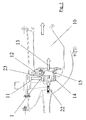
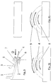
- Fig. 1 shows a schematic side sectional view of a Combustion chamber 10 with associated fuel injection.
- a schematic view of the supply of air to a inner swirler 14 and an outer swirler 15 are shown.
- the fuel-air mixture 13 flows in a known manner in the combustion chamber 10 a.
- the stabilization of the combustion takes place almost exclusively with air swirl, which is a recirculation of partially combusted gases allows.
- the fuel is often centrally through a nozzle introduced, which mounted on the center axis of the atomizer is.
- the fuel is often with considerable Overpressure injected into the air flow enough to Penetration to achieve and as much air with fuel to be able to premix.
- These pressure atomizers have to one the function to directly atomize fuel.
- the fuel gets through the air on a nebulizer lip accelerated and at the downstream end of this lip Torn into small drops and mixed with the air.
- a another way of putting the fuel on this nebulizer lip to raise, consists with a so-called film depositor, wherein Fuel is distributed as uniformly as possible in a film.
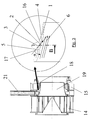
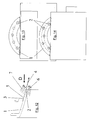
- FIG. 2 Another way of keeping the fuel as intense as possible to mix with a large part of the air, consists in one decentralized injection (Fig. 2) from the outer boundary a flow channel formed by a film feeder 1, which the majority of the air leads. This can be from a nebulizer lip or else from the outer nozzle contour.
- This injection is characterized in that, different as with a film-maker, the fuel is one defined Penetration into the main air flow should learn.
- the fuel nozzles are often through one in the radial direction very uneven velocity and mass flow distribution characterized. Due to the swirl of the air, which needed to stabilize the subsequent combustion is, the local air mass flow in the area of the radial outer boundary wall largest. Is the fuel out a few openings introduced into the flow, on the one hand the homogeneity of the fuel in the air in the circumferential direction impaired, on the other hand, the fuel can be very penetrate deeply into the flow and thus unintentionally in Regions mix and vaporize where not sufficient Air is available. This can also be done with a decentralized Injection occur.
- the invention is based on the object, a fuel injector to create the type mentioned, which at simple construction and reliable operation a uniform Mixing of fuel and air ensured.
- This essentially Parallel arrangement can also be up to a range of the absolute Diverge in parallelism through an acute angle is marked. Purely for structural reasons, it is not always possible, the fuel injection completely parallel perform. According to the invention, it is important that the fuel injection has a high axial component and the fuel thus not injected radially.
- the fuel openings may be on a radially inner wall
- the filmmaker can be created, but you can also at a Leave the rear edge of the same.
- the film-maker or the area of injection of the fuel is preferably arranged between two swirlers.
- the fuel openings in addition are inclined in the twisting direction of the air, i. an additional Have circumferential component. This can be in the same direction or be formed in the counter-twist. Furthermore, it is according to the invention possible, the fuel ports single row, multi-row, to arrange flush with each other or staggered to each other.
- the film-maker can also be designed like a lamella be to even better mixing of the air-fuel mixture to reach.
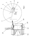
- Fig. 3 shows a simplified representation of a section by the film applicator 1 according to the invention, wherein fuel openings 2, in particular fuel bores 3, shown are whose center axes 5 by an angle ⁇ to the main flow direction 6 (wall-near flow direction in the inner swirl duct) are inclined.
- the reference numeral 16 shows a hired wall element of Filmlegers 1
- the reference numeral 17 shows an aerodynamic adapted film layer surface.
- the reference numeral 21 is a fuel line shown.
- the invention avoids the unwanted intrusion of the liquid Fuel in areas with low flow rates and the associated uneven fuel-air mixture.
- a proposed embodiment is shown in FIG. 3 shown.
- the fuel is here at a film layer not radially inward, i. with a high radial component the exit velocity of the fuel into an inner Injected swirl channel. Rather, in the proposed concept a high axial component of the exit velocity the fuel is present and the fuel is approaching parallel to the main flow direction of the inner swirl duct brought in.
- Fig. 3 are schematically the fuel ports as well as the Ausdüsung of the fuel shown.
- the fuel is initially through the openings shown over a hired against the air flow direction Angle ⁇ injected, which is formed as an acute angle.
- Angle ⁇ injected which is formed as an acute angle.
- the fuel openings in the circumferential direction arranged in the same or counter-rotation to the air flow be.
- the shape of the openings can also be different be executed, i. round, elliptical, etc.
- Construction will be the development of a fuel film in a radially very limited flow layer guaranteed. At the trailing edge of the filmmaker rips the Fuel film decreases and is accelerated by the presence of and twisted air from the outer and inner Flow channel homogeneously mixed.
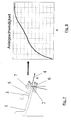
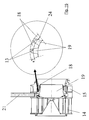
- FIG. 4 Another embodiment of the invention provides the injection of the fuel at the trailing edge of a flow divider between two swirlers before (Fig. 4).
- the speed maxima the accelerated and twisted in the swirl generator Air is near the wall of the formed flow divider, i.e. in the outer flow of the boundary layer both sides of the flow divider.
- Figs. 7 and 8 show the axial acceleration of the flow in the wake of the trailing edge of the flow divider, where x is the axial distance from the trailing edge of the flow divider is.
- FIG. 15 is to schematically illustrated a variant of the filmmaker.
- a Aero engine is aimed at different mass air flows To bring together loss as possible to a total flow.
- the mixture should be in the proposed burner concept however, to an improved mixture formation by a three-dimensional mixing of a twisted air stream with a partially premixed with air fuel flow to lead.
- the twisted air from the outer channel periodically penetrates into the inner channel through the shaping one. With an injection of the fuel in the inner or outer Spinal canal develops as the residence time increases downstream of the coater a fuel-air mixture. This Mixture may also be due to the shaping in the inner Penetrate swirl channel.
- the film layer can thus produce a flow layer be in a very intense mixture of the fuel-air mixture from the inner canal and pure air mixing can be done from the outer swirl duct or vice versa.
- the uniform temperature field with low absolute temperatures and low nitrogen oxide levels.
- Another feature the embodiment shown in Fig. 15 can also be a Flange-adapted spiral geometry of the lamellar film layer be in which the lamellar geometry correspondingly effective adapted to the air swirl near the wall of the filmmaker.
- the advantage of the invention is thus a practice-relevant solution the problem of premixing fuel homogeneously with air and this with as few, relatively large fuel ports a defined and not too large penetration depth of the Fuel into the air flow to achieve.
- Overall goal is the reduction of nitrogen oxide ejection of the gas turbine combustor with a robust and technically feasible fuel injection configuration.
Landscapes
- Engineering & Computer Science (AREA)
- Chemical & Material Sciences (AREA)
- Combustion & Propulsion (AREA)
- Mechanical Engineering (AREA)
- General Engineering & Computer Science (AREA)
- Nozzles For Spraying Of Liquid Fuel (AREA)
- Spray-Type Burners (AREA)
Applications Claiming Priority (2)
| Application Number | Priority Date | Filing Date | Title |
|---|---|---|---|
| DE2003148604 DE10348604A1 (de) | 2003-10-20 | 2003-10-20 | Kraftstoffeinspritzdüse mit filmartiger Kraftstoffplatzierung |
| DE10348604 | 2003-10-20 |
Publications (2)
| Publication Number | Publication Date |
|---|---|
| EP1526332A2 true EP1526332A2 (fr) | 2005-04-27 |
| EP1526332A3 EP1526332A3 (fr) | 2012-02-15 |
Family
ID=34384376
Family Applications (1)
| Application Number | Title | Priority Date | Filing Date |
|---|---|---|---|
| EP20040023823 Withdrawn EP1526332A3 (fr) | 2003-10-20 | 2004-10-06 | Injecteur de combustible |
Country Status (3)
| Country | Link |
|---|---|
| US (1) | US9033263B2 (fr) |
| EP (1) | EP1526332A3 (fr) |
| DE (1) | DE10348604A1 (fr) |
Cited By (4)
| Publication number | Priority date | Publication date | Assignee | Title |
|---|---|---|---|---|
| RU2523519C2 (ru) * | 2009-03-17 | 2014-07-20 | Сименс Акциенгезелльшафт | Способ эксплуатации горелки, горелка, в частности для газовой турбины и газовая турбина |
| EP3076082A1 (fr) * | 2015-03-31 | 2016-10-05 | Delavan Inc | Buses de combustible |
| US10309651B2 (en) | 2011-11-03 | 2019-06-04 | Delavan Inc | Injectors for multipoint injection |
| US10385809B2 (en) | 2015-03-31 | 2019-08-20 | Delavan Inc. | Fuel nozzles |
Families Citing this family (10)
| Publication number | Priority date | Publication date | Assignee | Title |
|---|---|---|---|---|
| US20060283181A1 (en) * | 2005-06-15 | 2006-12-21 | Arvin Technologies, Inc. | Swirl-stabilized burner for thermal management of exhaust system and associated method |
| US8453454B2 (en) * | 2010-04-14 | 2013-06-04 | General Electric Company | Coannular oil injection nozzle |
| EP3087323B1 (fr) * | 2014-04-03 | 2019-08-21 | Siemens Aktiengesellschaft | Injecteur de combustible, brûleur avec un tel injecteur de combustible, et turbine à gaz munie dudit brûleur |
| EP3143334B1 (fr) | 2014-05-12 | 2020-08-12 | General Electric Company | Cartouche de combustible liquide pour la formation de film |
| US10132500B2 (en) | 2015-10-16 | 2018-11-20 | Delavan Inc. | Airblast injectors |
| US20180058696A1 (en) * | 2016-08-23 | 2018-03-01 | General Electric Company | Fuel-air mixer assembly for use in a combustor of a turbine engine |
| US10876477B2 (en) | 2016-09-16 | 2020-12-29 | Delavan Inc | Nozzles with internal manifolding |
| US10344981B2 (en) | 2016-12-16 | 2019-07-09 | Delavan Inc. | Staged dual fuel radial nozzle with radial liquid fuel distributor |
| US20180335214A1 (en) * | 2017-05-18 | 2018-11-22 | United Technologies Corporation | Fuel air mixer assembly for a gas turbine engine combustor |
| US11149948B2 (en) | 2017-08-21 | 2021-10-19 | General Electric Company | Fuel nozzle with angled main injection ports and radial main injection ports |
Citations (6)
| Publication number | Priority date | Publication date | Assignee | Title |
|---|---|---|---|---|
| US3866413A (en) * | 1973-01-22 | 1975-02-18 | Parker Hannifin Corp | Air blast fuel atomizer |
| DE3819898A1 (de) | 1988-06-11 | 1989-12-14 | Daimler Benz Ag | Brennkammer fuer eine thermische stroemungsmaschine |
| FR2673705A1 (fr) * | 1991-03-06 | 1992-09-11 | Snecma | Chambre de combustion de turbomachine munie d'un dispositif anti-cokefaction du fond de ladite chambre. |
| DE19532264A1 (de) | 1995-09-01 | 1997-03-06 | Mtu Muenchen Gmbh | Einrichtung zur Aufbereitung eines Gemisches aus Brennstoff und Luft an Brennkammern für Gasturbinentriebwerke |
| EP1087178A1 (fr) * | 1999-09-23 | 2001-03-28 | Nuovo Pignone Holding S.P.A. | Chambre de prémélange pour turbines à gaz |
| EP1331441A1 (fr) | 2002-01-21 | 2003-07-30 | National Aerospace Laboratory of Japan | Buse d'atomisation de liquide |
Family Cites Families (46)
| Publication number | Priority date | Publication date | Assignee | Title |
|---|---|---|---|---|
| US3955361A (en) * | 1971-12-15 | 1976-05-11 | Phillips Petroleum Company | Gas turbine combustor with controlled fuel mixing |
| SE371685B (fr) | 1972-04-21 | 1974-11-25 | Stal Laval Turbin Ab | |
| GB1421399A (en) | 1972-11-13 | 1976-01-14 | Snecma | Fuel injectors |
| US3930369A (en) * | 1974-02-04 | 1976-01-06 | General Motors Corporation | Lean prechamber outflow combustor with two sets of primary air entrances |
| US3980233A (en) * | 1974-10-07 | 1976-09-14 | Parker-Hannifin Corporation | Air-atomizing fuel nozzle |
| US4170108A (en) * | 1975-04-25 | 1979-10-09 | Rolls-Royce Limited | Fuel injectors for gas turbine engines |
| US4141213A (en) * | 1977-06-23 | 1979-02-27 | General Motors Corporation | Pilot flame tube |
| US4218020A (en) * | 1979-02-23 | 1980-08-19 | General Motors Corporation | Elliptical airblast nozzle |
| US4425755A (en) | 1980-09-16 | 1984-01-17 | Rolls-Royce Limited | Gas turbine dual fuel burners |
| CH670296A5 (en) | 1986-02-24 | 1989-05-31 | Bbc Brown Boveri & Cie | Gas turbine fuel nozzle - has externally-supported premixing chamber for liq. fuel and air |
| CA1306873C (fr) * | 1987-04-27 | 1992-09-01 | Jack R. Taylor | Injecteur de combustible a faible teneur en coke, pour turbine a gaz |
| DE4228816C2 (de) * | 1992-08-29 | 1998-08-06 | Mtu Muenchen Gmbh | Brenner für Gasturbinentriebwerke |
| US5251447A (en) * | 1992-10-01 | 1993-10-12 | General Electric Company | Air fuel mixer for gas turbine combustor |
| US5505045A (en) | 1992-11-09 | 1996-04-09 | Fuel Systems Textron, Inc. | Fuel injector assembly with first and second fuel injectors and inner, outer, and intermediate air discharge chambers |
| FR2698157B1 (fr) * | 1992-11-18 | 1994-12-16 | Snecma | Système d'injection aérodynamique de chambre de combustion. |
| US5303554A (en) | 1992-11-27 | 1994-04-19 | Solar Turbines Incorporated | Low NOx injector with central air swirling and angled fuel inlets |
| DE4316474A1 (de) | 1993-05-17 | 1994-11-24 | Abb Management Ag | Vormischbrenner zum Betrieb einer Brennkraftmaschine, einer Brennkammer einer Gasturbogruppe oder Feuerungsanlage |
| US5479781A (en) | 1993-09-02 | 1996-01-02 | General Electric Company | Low emission combustor having tangential lean direct injection |
| US5351477A (en) * | 1993-12-21 | 1994-10-04 | General Electric Company | Dual fuel mixer for gas turbine combustor |
| DE4424597B4 (de) | 1994-07-13 | 2006-03-23 | Alstom | Verbrennungsvorrichtung |
| US5701732A (en) | 1995-01-24 | 1997-12-30 | Delavan Inc. | Method and apparatus for purging of gas turbine injectors |
| US5680766A (en) * | 1996-01-02 | 1997-10-28 | General Electric Company | Dual fuel mixer for gas turbine combustor |
| US5778676A (en) * | 1996-01-02 | 1998-07-14 | General Electric Company | Dual fuel mixer for gas turbine combustor |
| GB2319078B (en) * | 1996-11-08 | 1999-11-03 | Europ Gas Turbines Ltd | Combustor arrangement |
| JP3619626B2 (ja) * | 1996-11-29 | 2005-02-09 | 株式会社東芝 | ガスタービン燃焼器の運転方法 |
| US5816049A (en) * | 1997-01-02 | 1998-10-06 | General Electric Company | Dual fuel mixer for gas turbine combustor |
| DE19729246C2 (de) | 1997-07-09 | 2001-06-28 | Deutsch Zentr Luft & Raumfahrt | Zerstäuberdüse für die Kraftstoffzerstäubung in Brennern |
| US5966937A (en) * | 1997-10-09 | 1999-10-19 | United Technologies Corporation | Radial inlet swirler with twisted vanes for fuel injector |
| GB9726697D0 (en) | 1997-12-18 | 1998-02-18 | Secr Defence | Fuel injector |
| DE19803879C1 (de) * | 1998-01-31 | 1999-08-26 | Mtu Muenchen Gmbh | Zweistoffbrenner |
| GB2333832A (en) * | 1998-01-31 | 1999-08-04 | Europ Gas Turbines Ltd | Multi-fuel gas turbine engine combustor |
| US6119459A (en) * | 1998-08-18 | 2000-09-19 | Alliedsignal Inc. | Elliptical axial combustor swirler |
| EP0994300B1 (fr) | 1998-10-14 | 2003-11-26 | ALSTOM (Switzerland) Ltd | Brûleur pour la conduite d'un générateur de chaleur |
| EP1096201A1 (fr) * | 1999-10-29 | 2001-05-02 | Siemens Aktiengesellschaft | Brûleur |
| US6272840B1 (en) | 2000-01-13 | 2001-08-14 | Cfd Research Corporation | Piloted airblast lean direct fuel injector |
| US6474071B1 (en) * | 2000-09-29 | 2002-11-05 | General Electric Company | Multiple injector combustor |
| US6363726B1 (en) * | 2000-09-29 | 2002-04-02 | General Electric Company | Mixer having multiple swirlers |
| DE10056243A1 (de) * | 2000-11-14 | 2002-05-23 | Alstom Switzerland Ltd | Brennkammer und Verfahren zum Betrieb dieser Brennkammer |
| FR2836986B1 (fr) * | 2002-03-07 | 2004-11-19 | Snecma Moteurs | Systeme d'injection multi-modes d'un melange air/carburant dans une chambre de combustion |
| EP1499800B1 (fr) * | 2002-04-26 | 2011-06-29 | Rolls-Royce Corporation | Module de premelange de combustible pour chambre de combustion de turbine a gaz |
| DE10219354A1 (de) * | 2002-04-30 | 2003-11-13 | Rolls Royce Deutschland | Gasturbinenbrennkammer mit gezielter Kraftstoffeinbringung zur Verbesserung der Homogenität des Kraftstoff-Luft-Gemisches |
| US6986255B2 (en) * | 2002-10-24 | 2006-01-17 | Rolls-Royce Plc | Piloted airblast lean direct fuel injector with modified air splitter |
| JP4065947B2 (ja) * | 2003-08-05 | 2008-03-26 | 独立行政法人 宇宙航空研究開発機構 | ガスタービン燃焼器用燃料・空気プレミキサー |
| DE10340826A1 (de) * | 2003-09-04 | 2005-03-31 | Rolls-Royce Deutschland Ltd & Co Kg | Homogene Gemischbildung durch verdrallte Einspritzung des Kraftstoffs |
| US6968255B1 (en) * | 2004-10-22 | 2005-11-22 | Pulse Microsystems, Ltd. | Method and system for automatically deriving stippling stitch designs in embroidery patterns |
| JP2006300448A (ja) * | 2005-04-22 | 2006-11-02 | Mitsubishi Heavy Ind Ltd | ガスタービンの燃焼器 |
-
2003
- 2003-10-20 DE DE2003148604 patent/DE10348604A1/de not_active Withdrawn
-
2004
- 2004-10-06 EP EP20040023823 patent/EP1526332A3/fr not_active Withdrawn
- 2004-10-19 US US10/967,320 patent/US9033263B2/en not_active Expired - Fee Related
Patent Citations (6)
| Publication number | Priority date | Publication date | Assignee | Title |
|---|---|---|---|---|
| US3866413A (en) * | 1973-01-22 | 1975-02-18 | Parker Hannifin Corp | Air blast fuel atomizer |
| DE3819898A1 (de) | 1988-06-11 | 1989-12-14 | Daimler Benz Ag | Brennkammer fuer eine thermische stroemungsmaschine |
| FR2673705A1 (fr) * | 1991-03-06 | 1992-09-11 | Snecma | Chambre de combustion de turbomachine munie d'un dispositif anti-cokefaction du fond de ladite chambre. |
| DE19532264A1 (de) | 1995-09-01 | 1997-03-06 | Mtu Muenchen Gmbh | Einrichtung zur Aufbereitung eines Gemisches aus Brennstoff und Luft an Brennkammern für Gasturbinentriebwerke |
| EP1087178A1 (fr) * | 1999-09-23 | 2001-03-28 | Nuovo Pignone Holding S.P.A. | Chambre de prémélange pour turbines à gaz |
| EP1331441A1 (fr) | 2002-01-21 | 2003-07-30 | National Aerospace Laboratory of Japan | Buse d'atomisation de liquide |
Cited By (7)
| Publication number | Priority date | Publication date | Assignee | Title |
|---|---|---|---|---|
| RU2523519C2 (ru) * | 2009-03-17 | 2014-07-20 | Сименс Акциенгезелльшафт | Способ эксплуатации горелки, горелка, в частности для газовой турбины и газовая турбина |
| US9032736B2 (en) | 2009-03-17 | 2015-05-19 | Siemens Aktiengesellschaft | Method for operating a burner and burner, in particular for a gas turbine |
| US10309651B2 (en) | 2011-11-03 | 2019-06-04 | Delavan Inc | Injectors for multipoint injection |
| EP3076082A1 (fr) * | 2015-03-31 | 2016-10-05 | Delavan Inc | Buses de combustible |
| US9897321B2 (en) | 2015-03-31 | 2018-02-20 | Delavan Inc. | Fuel nozzles |
| US10385809B2 (en) | 2015-03-31 | 2019-08-20 | Delavan Inc. | Fuel nozzles |
| US11111888B2 (en) | 2015-03-31 | 2021-09-07 | Delavan Inc. | Fuel nozzles |
Also Published As
| Publication number | Publication date |
|---|---|
| EP1526332A3 (fr) | 2012-02-15 |
| US9033263B2 (en) | 2015-05-19 |
| DE10348604A1 (de) | 2005-07-28 |
| US20050133642A1 (en) | 2005-06-23 |
Similar Documents
| Publication | Publication Date | Title |
|---|---|---|
| EP0623786B1 (fr) | Chambre de combustion | |
| DE4426351B4 (de) | Brennkammer für eine Gasturbine | |
| DE10304386B4 (de) | Doppelfluid-Verwirbelungsdüse mit selbstreinigendem Zapfen | |
| EP1802915B1 (fr) | Bruleur pour turbine a gaz | |
| EP0899508B1 (fr) | Brûleur pour un dispositif à chaleur | |
| CH680467A5 (fr) | ||
| EP1526332A2 (fr) | Injecteur de combustible | |
| EP2423597B1 (fr) | Brûleur à prémélange pour une turbine à gaz | |
| CH687832A5 (de) | Brennstoffzufuehreinrichtung fuer Brennkammer. | |
| EP0775869B1 (fr) | Brûleur à prémélange | |
| EP1512912A2 (fr) | Mélange homogène obtenu par injection tourbillonnaire du carburant | |
| DE102009026130A1 (de) | Gasturbinenvormischer mit kraterartigen Brennstoffinjektionsstellen | |
| EP0851172B1 (fr) | Brûleur et méthode pour la mise en oeuvre d'une chambre de combustion avec un combustible liquide et/ou gazeux | |
| EP1359376B1 (fr) | Chambre de combustion pour turbine à gaz avec injection précise de carburant pour améliorer l'homogenéité du mélange air-carburant | |
| DE19532264C2 (de) | Einrichtung zur Aufbereitung eines Gemisches aus Brennstoff und Luft an Brennkammern für Gasturbinentriebwerke | |
| DE102017118165B4 (de) | Brennerkopf, Brennersystem und Verwendung des Brennersystems | |
| EP1878972A2 (fr) | Dispositif d'injection de carburant pour une turbine à gaz volatile | |
| EP0833104B1 (fr) | Brûleur pour le fonctionnement d'une chambre de combustion | |
| EP0961905B1 (fr) | Procede et dispositif de combustion d'un combustible | |
| EP0913630B1 (fr) | Brûleur pour la mise en oeuvre d'un générateur de chaleur | |
| DE69727899T2 (de) | Tangentiale Brennstoffeintrittsdüse | |
| DE102023103446A1 (de) | Zufuhranordnung zur Zufuhr von Oxidator und flüssigem Brennstoff in einen Brennraum, Brennersystem und Verfahren | |
| EP4737802A1 (fr) | Buse d'alimentation en air et en carburant liquide d'une chambre de combustion et moteur | |
| WO2009109452A1 (fr) | Ensemble brûleur et son utilisation | |
| DE19542164A1 (de) | Vormischbrenner |
Legal Events
| Date | Code | Title | Description |
|---|---|---|---|
| PUAI | Public reference made under article 153(3) epc to a published international application that has entered the european phase |
Free format text: ORIGINAL CODE: 0009012 |
|
| AK | Designated contracting states |
Kind code of ref document: A2 Designated state(s): AT BE BG CH CY CZ DE DK EE ES FI FR GB GR HU IE IT LI LU MC NL PL PT RO SE SI SK TR |
|
| AX | Request for extension of the european patent |
Extension state: AL HR LT LV MK |
|
| RIN1 | Information on inventor provided before grant (corrected) |
Inventor name: RACKWITZ, LEIF |
|
| PUAL | Search report despatched |
Free format text: ORIGINAL CODE: 0009013 |
|
| AK | Designated contracting states |
Kind code of ref document: A3 Designated state(s): AT BE BG CH CY CZ DE DK EE ES FI FR GB GR HU IE IT LI LU MC NL PL PT RO SE SI SK TR |
|
| AX | Request for extension of the european patent |
Extension state: AL HR LT LV MK |
|
| RIC1 | Information provided on ipc code assigned before grant |
Ipc: F23R 3/28 20060101ALI20120112BHEP Ipc: F23D 11/10 20060101AFI20120112BHEP |
|
| 17P | Request for examination filed |
Effective date: 20120814 |
|
| AKX | Designation fees paid |
Designated state(s): DE FR GB |
|
| 17Q | First examination report despatched |
Effective date: 20130618 |
|
| STAA | Information on the status of an ep patent application or granted ep patent |
Free format text: STATUS: THE APPLICATION IS DEEMED TO BE WITHDRAWN |
|
| 18D | Application deemed to be withdrawn |
Effective date: 20160310 |