EP1526493B1 - Procédé pour affichage de l'information routière dans un véhicule - Google Patents
Procédé pour affichage de l'information routière dans un véhicule Download PDFInfo
- Publication number
- EP1526493B1 EP1526493B1 EP04024478A EP04024478A EP1526493B1 EP 1526493 B1 EP1526493 B1 EP 1526493B1 EP 04024478 A EP04024478 A EP 04024478A EP 04024478 A EP04024478 A EP 04024478A EP 1526493 B1 EP1526493 B1 EP 1526493B1
- Authority
- EP
- European Patent Office
- Prior art keywords
- traffic
- vehicle
- displayed
- bottlenecks
- queuing
- Prior art date
- Legal status (The legal status is an assumption and is not a legal conclusion. Google has not performed a legal analysis and makes no representation as to the accuracy of the status listed.)
- Expired - Lifetime
Links
- 238000000034 method Methods 0.000 title claims abstract description 36
- 238000000819 phase cycle Methods 0.000 claims description 3
- 238000005054 agglomeration Methods 0.000 description 9
- 230000002776 aggregation Effects 0.000 description 9
- 238000011144 upstream manufacturing Methods 0.000 description 7
- 230000001360 synchronised effect Effects 0.000 description 6
- 238000010276 construction Methods 0.000 description 3
- 238000004891 communication Methods 0.000 description 1
- 238000001514 detection method Methods 0.000 description 1
- 238000010586 diagram Methods 0.000 description 1
- 238000004090 dissolution Methods 0.000 description 1
- 230000000694 effects Effects 0.000 description 1
- 238000013277 forecasting method Methods 0.000 description 1
- 238000012544 monitoring process Methods 0.000 description 1
- 238000004393 prognosis Methods 0.000 description 1
- 230000001105 regulatory effect Effects 0.000 description 1
- 230000007704 transition Effects 0.000 description 1
Images




Classifications
-
- G—PHYSICS
- G08—SIGNALLING
- G08G—TRAFFIC CONTROL SYSTEMS
- G08G1/00—Traffic control systems for road vehicles
- G08G1/09—Arrangements for giving variable traffic instructions
- G08G1/0962—Arrangements for giving variable traffic instructions having an indicator mounted inside the vehicle, e.g. giving voice messages
- G08G1/0967—Systems involving transmission of highway information, e.g. weather, speed limits
- G08G1/096708—Systems involving transmission of highway information, e.g. weather, speed limits where the received information might be used to generate an automatic action on the vehicle control
- G08G1/096716—Systems involving transmission of highway information, e.g. weather, speed limits where the received information might be used to generate an automatic action on the vehicle control where the received information does not generate an automatic action on the vehicle control
-
- G—PHYSICS
- G01—MEASURING; TESTING
- G01C—MEASURING DISTANCES, LEVELS OR BEARINGS; SURVEYING; NAVIGATION; GYROSCOPIC INSTRUMENTS; PHOTOGRAMMETRY OR VIDEOGRAMMETRY
- G01C21/00—Navigation; Navigational instruments not provided for in groups G01C1/00 - G01C19/00
- G01C21/26—Navigation; Navigational instruments not provided for in groups G01C1/00 - G01C19/00 specially adapted for navigation in a road network
- G01C21/34—Route searching; Route guidance
- G01C21/36—Input/output arrangements for on-board computers
- G01C21/3691—Retrieval, searching and output of information related to real-time traffic, weather, or environmental conditions
- G01C21/3694—Output thereof on a road map
-
- G—PHYSICS
- G08—SIGNALLING
- G08G—TRAFFIC CONTROL SYSTEMS
- G08G1/00—Traffic control systems for road vehicles
- G08G1/09—Arrangements for giving variable traffic instructions
- G08G1/0962—Arrangements for giving variable traffic instructions having an indicator mounted inside the vehicle, e.g. giving voice messages
- G08G1/0967—Systems involving transmission of highway information, e.g. weather, speed limits
- G08G1/096733—Systems involving transmission of highway information, e.g. weather, speed limits where a selection of the information might take place
- G08G1/096741—Systems involving transmission of highway information, e.g. weather, speed limits where a selection of the information might take place where the source of the transmitted information selects which information to transmit to each vehicle
-
- G—PHYSICS
- G08—SIGNALLING
- G08G—TRAFFIC CONTROL SYSTEMS
- G08G1/00—Traffic control systems for road vehicles
- G08G1/09—Arrangements for giving variable traffic instructions
- G08G1/0962—Arrangements for giving variable traffic instructions having an indicator mounted inside the vehicle, e.g. giving voice messages
- G08G1/0967—Systems involving transmission of highway information, e.g. weather, speed limits
- G08G1/096766—Systems involving transmission of highway information, e.g. weather, speed limits where the system is characterised by the origin of the information transmission
- G08G1/096775—Systems involving transmission of highway information, e.g. weather, speed limits where the system is characterised by the origin of the information transmission where the origin of the information is a central station
-
- G—PHYSICS
- G08—SIGNALLING
- G08G—TRAFFIC CONTROL SYSTEMS
- G08G1/00—Traffic control systems for road vehicles
- G08G1/09—Arrangements for giving variable traffic instructions
- G08G1/0962—Arrangements for giving variable traffic instructions having an indicator mounted inside the vehicle, e.g. giving voice messages
- G08G1/0967—Systems involving transmission of highway information, e.g. weather, speed limits
- G08G1/096766—Systems involving transmission of highway information, e.g. weather, speed limits where the system is characterised by the origin of the information transmission
- G08G1/096791—Systems involving transmission of highway information, e.g. weather, speed limits where the system is characterised by the origin of the information transmission where the origin of the information is another vehicle
-
- G—PHYSICS
- G08—SIGNALLING
- G08G—TRAFFIC CONTROL SYSTEMS
- G08G1/00—Traffic control systems for road vehicles
- G08G1/09—Arrangements for giving variable traffic instructions
- G08G1/0962—Arrangements for giving variable traffic instructions having an indicator mounted inside the vehicle, e.g. giving voice messages
- G08G1/0968—Systems involving transmission of navigation instructions to the vehicle
- G08G1/0969—Systems involving transmission of navigation instructions to the vehicle having a display in the form of a map
Definitions
- the invention relates to a method for vehicle-side display of traffic information, in which selbige vehicle determined and / or identified outside the vehicle and transmitted to the vehicle and displayed on the vehicle side.
- Laid-open specification DE 100 37 827 A1 discloses a method in which location and extent of forecasted storage areas are displayed spatially resolved on the basis of a digital road network map.
- the term "spatially resolved” is to be understood here and below, the statement at which point of the considered traffic route network is the traffic jam or another traffic object to be displayed.
- predicted travel times may be displayed in the form of time equidistant lines or zones, the estimated time of arrival at particular route points, and / or the likelihood that the forecast will assume the occurrence of the congestion involved.
- a determined optimal route and, if required, additionally one or more determined alternative routes can be displayed together with associated arrival times or loss times of the alternative routes with respect to the optimal route.
- Analog traffic jamming objects occur in traffic networks of agglomerations in which the traffic is dominated by traffic-controlled network nodes in the form of upstream such traffic-regulated network node forming queue traffic patterns that can be adequately taken into account in corresponding traffic forecasts, see for further details such as the published patent DE 199 40 957 A1 and DE 100 36 792 A1 and the literature cited therein.
- traffic dynamics are typically dominated by the traffic control measures at the network nodes, such as traffic lights at road intersections, ie Traffic-controlled network nodes form effective bottlenecks at which queuing traffic patterns arise in the case of corresponding traffic volumes, hereinafter also referred to simply as queues.
- a generic method disclosed in the published patent application DE 101 19 730 A1 is particularly suitable for displaying determined effective bottlenecks and / or associated, determined patterns of dense traffic of a motorway network. These are displayed in a spatially resolved on a screen, preferably on a digital road network map and / or in a route profile display and / or a travel time profile representation driving direction selective.
- detailed information about the determined patterns of dense traffic can be displayed, in particular relevant forecast information such as probability of emergence, vehicle arrival time, departure time, residence time, extent, traffic density on the respective lane, average vehicle speed, time of origin, time of dissolution, travel time loss and / or internal structure.
- the invention is based on the technical problem of providing a method of the type mentioned by the vehicle occupants and in particular the driver vividly, reliably and accurately informed about the relevant traffic for further driving in particular in metropolitan areas, in which the traffic of the dynamics is dominated by queue traffic patterns.
- the invention solves this problem by providing a traffic information display method having the features of claim 1.
- a traffic information display method having the features of claim 1.
- the traffic information to be displayed at least effective congestion bottlenecks and associated current and / or future expected queue traffic patterns are determined and spatially resolved, i. indicating their location on the underlying agglomeration network.
- the display of effective congestion bottlenecks or queue traffic patterns is selected direction of travel selectively only in the possible direction of travel of the vehicle so that the driver does not interfere with the display of irrelevant to him information, for. is loaded on the traffic lane sections on the traffic situation.
- the effective conurbation bottlenecks are displayed with any associated queues symbolically on a digital road map.
- the symbol-driven display of effective metropolitan bottlenecks is clear to the user.
- associated detailed information in the desired type and number can be displayed, be it automatically with the symbol display of agglomeration bottlenecks or only on user request.
- the queues are shown in their longitudinal extent together with the associated number of waiting free phases and / or the associated waiting time. This gives the user a detailed picture of the queue in question.
- a further developed according to claim 6 method comprises displaying a determined optimal route and one or more alternative routes together with associated predicted travel time information. The driver is informed in this way very comfortable on cheap routes.
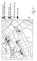
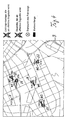
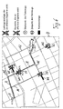
- the figures illustrate exemplary traffic information displays on a vehicle-side screen, as provided by various advantageous implementations of the method according to the invention for the vehicle-side traffic information display.
- Characteristic component of the various process implementations is in each case that the displayed traffic information in addition to any other conventional traffic information in particular information about the existence of effective congestion bottlenecks and their location on the considered road network and information about any queue traffic patterns, in the present case also referred to as queues, contained upstream of such effective agglomeration bottlenecks.
- a road network is considered for the examples shown, alternatively, however, the inventive method is also suitable for another type of road network with appropriate traffic characteristics, such as a rail network.
- the examples represented by the different figures may vary depending on the application may be such different process implementations, or several of these examples may be part of a shared process implementation, which then has a switching capability between these different types of traffic information display on the screen.
- the means and methods underlying the present traffic information display method for detecting the current and / or predicted traffic condition to be displayed are e.g. in the related patent applications of the applicant described in detail, see also the cited documents and cited therein further literature, so that it can be referred to and this requires no further explanation.
- suitable means and methods for determining the location of effective bottlenecks in metropolitan area networks and optionally also in expressway networks and for determining queues or patterns of dense traffic occurring there may be required for the present method.
- this can be both systems working autonomously with the vehicle, systems operating with vehicle-vehicle communication and / or systems operating with a traffic center for determining the current and / or forecasting of the future traffic condition on a road network of interest, above all the detection of customizable traffic obstruction objects, such as effective congestion bottlenecks, in particular, light signal-controlled network nodes, and queues formed before them, as well as wide jams, synchronized traffic and compressed synchronized traffic, and patterns built up from such traffic state phases, enable dense traffic from effective bottlenecks in expressway network areas.
- traffic obstruction objects such as effective congestion bottlenecks, in particular, light signal-controlled network nodes, and queues formed before them, as well as wide jams, synchronized traffic and compressed synchronized traffic, and patterns built up from such traffic state phases, enable dense traffic from effective bottlenecks in expressway network areas.
- FIG. 1 illustrates, as a basic form, a method example in which, based on a digital road map, starting from the respective current vehicle location as a starting point is determined and displayed whether and if so where specific for the possible directions of travel of a considered vehicle F effective agglomeration bottlenecks within a vehicle location containing metropolitan area network area, which could meet the vehicle F in his further drive depending on the selected direction.
- effective agglomeration bottlenecks are formed, in particular, by traffic light systems at network nodes, ie intersection areas, and by construction sites.
- these are four traffic signal bottlenecks E1 to E4 and a construction site bottleneck E5.
- the bottlenecks E1 to E5 are symbolically displayed as crosses in conjunction with an intuitive traffic sign representation at the corresponding route point of the digital road map on a screen B in the vehicle F. This allows the driver to respond promptly when needed.
- queues W1 to W5 are displayed, which are forecasted for the time at the associated bottleneck E1 to E5, to which the vehicle F is expected to arrive on the basis of the results of the traffic forecast and which it then encounters.
- the display of the queues W1 to W5 is performed by bars having a length corresponding to the predicted queue length. These may also be so-called cross queues, as in the case of queues W1 and W3, which extend upstream beyond one or more network nodes.
- the associated probability of occurrence of their occurrence in percent and the estimated time of arrival are also indicated.
- more or less such detailed information about predicted metropolitan queues may be displayed, alternatively or automatically, or only to a particular user request towards, for example, by appropriate operation of controls for the screen B by a vehicle occupant.
- only the identified congestion bottlenecks can be represented by their corresponding symbols on the digital road map or only together with the queue bars or additionally conurbation bottlenecks on opposite direction lanes with or without associated queues and detailed information associated with them.
- FIG. 2 shows a display variant in which travel time equidistance zones are reproduced in addition to the information of FIG. the vehicle F can get to any point in the zone concerned, with the likely same maximum time of arrival, on the basis of the predicted traffic situation.
- the predicted arrival time is given for the zone-limiting equidistant lines.
- three equidistant lines D1, D2, D3 are explicitly reproduced, to which a predicted travel time interval of 5 minutes each belongs.
- the queue bars and predicted event probabilities in addition to the symbols of the identified congestion bottlenecks, the queue bars and predicted event probabilities, the number of free phases that are likely to be awaited on arriving at the queue in question is displayed until the associated bottleneck can be passed. Specifically, it is in the light signal systems to the number of corresponding green phases, in the present case also called traffic light cycles. This gives the user a further indication of the strength of the queue traffic jam.
- Fig. 4 shows a variant of Fig. 3, in which, instead of the number of traffic light cycles for each forecasted queue W1 to W5, the probable waiting time in seconds which the vehicle F needs to pass the queue W1 to W5 is indicated.
- FIG. 5 shows a method example in which predicted arrival times are indicated as times for conurbation bottlenecks and for network nodes in addition to the symbols of the identified congestion bottlenecks E1 to E5 and the longitudinal bars of the associated predicted queues W1 to W5 which the vehicle F could possibly drive.
- route recommendations resulting from the traffic forecast are displayed in addition to the congestion bottlenecks E1 to E5 and the associated predicted queues W1 to W5, namely a predicted optimal route R and one or more alternative routes, in the representation of FIG Fig. 6 two alternative routes A1 and A2.
- the route recommendation is based on a traffic prognosis which corrects any traffic disruption objects in time, i. at the time of the predicted arrival of the vehicle F, predicts, in particular, the queues W1 to W5.
- the route R proves to be optimal, i. shortest in time, although it passes over the queue W1.
- the estimated time of arrival is indicated on the illustrated digital road map.
- FIGS. 7 and 8 illustrate alternative ways of presenting a predicted route as a route axis or time axis profile.
- FIG. 7 shows a track axis, which in turn can be visually displayed on the screen B of the vehicle, with a track or road section Sa lying in front of the vehicle F and with an associated scale of FIG Distance s from the current vehicle location.
- a time axis representation according to FIG. 8 can be selected on the vehicle-side screen, in which the route section Sa is displayed in advance of the vehicle F in time-length form with an associated linear time scale indicating the predicted travel time.
- FIGS. 7 and 8 in these representations along the track or timeline at the location concerned, the predicted traffic signal bottlenecks as symbols and predicted queues W6, W7 at these as bars and any speed limits and Turning represented in corresponding traffic sign shape.
- other or further traffic information along the route or time axis can be displayed.
- the examples of Figs. 7 and 8 show a case in which, after turning, a road section is driven on which there is an effective constriction E6 before which a pattern M dense traffic formed upon arrival of the vehicle F according to the underlying traffic forecast Has.
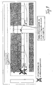
- a detailed representation of the respective predicted queue can be activated, as shown by way of example in FIG. 9, at the request of the driver.
- the lane area upstream of the queue causing congestion bottleneck is represented for this purpose and the queue is entered therein as a bar having a bar length corresponding to the queue length, preferably individually for each lane.
- the queue bar entry includes a subdivision into beam length units of each free phase cycle, there called a wait cycle. The length of each wait cycle thus gives the vehicle during a free phase, such as a traffic light green phase expected distance traveled in the queue.
- 9 is an overall queue W8 with a total length of 9.3 wait cycles on a right turn lane, ie a vehicle approaching the queue W8 is likely to turn right at the traffic light controlled intersection in the tenth green phase , There is no overlapping queue on an additionally displayed left turn lane. Obviously, this representation provides the driver with very detailed information about a queue that he may encounter later in the journey.
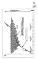
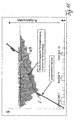
- a predicted queue W9 upstream of a congestion bottleneck such as a congestion-related constriction
- a congestion bottleneck such as a congestion-related constriction
- the green-phase time intervals and the red-phase time intervals of the traffic signal system are marked on the time axis t, the sum of a red-phase time and a green-phase time being designated as the circulation time, which represents the time period length of the traffic signal system control.
- the predicted movement of the vehicle F is indicated as the corresponding predicted driving line.
- a calculated average speed of the vehicle in the queue is used, while in the case of Fig. 11 the predicted vehicle movement within the queue W9 is based on its exact route and time is reproduced.
- the method according to the invention comprises both a traffic forecast of effective congestion bottlenecks and resulting queues in metropolitan areas of a considered road network as well as effective motorway bottlenecks and on these resulting patterns dense traffic in highways areas of the road network.
- the determined metropolitan bottlenecks with associated queues and the expressway bottlenecks with associated dense traffic patterns are then displayed combined on a digital road map on the screen B in the vehicle.
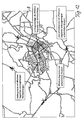
- FIG. 12 shows by way of example such a screen display with a traffic signal bottleneck in a conurbation area and four effective expressway bottlenecks in a motorway network area.
- the associated queues or patterns dense traffic are in turn each represented with bars of appropriate length.
- further detailed information on the individual bottlenecks can be displayed as needed, as explained above for the other examples shown.
- the described embodiments show that the inventive method allows a comfortable and realistic reproduction of predicted traffic disturbance patterns in metropolitan areas and optionally additionally in expressway network areas on the basis of suitable conventional traffic forecasting methods.
Landscapes
- Physics & Mathematics (AREA)
- General Physics & Mathematics (AREA)
- Life Sciences & Earth Sciences (AREA)
- Atmospheric Sciences (AREA)
- Engineering & Computer Science (AREA)
- Radar, Positioning & Navigation (AREA)
- Remote Sensing (AREA)
- Ecology (AREA)
- Biodiversity & Conservation Biology (AREA)
- Environmental & Geological Engineering (AREA)
- Environmental Sciences (AREA)
- Automation & Control Theory (AREA)
- Traffic Control Systems (AREA)
- Navigation (AREA)
- Instructional Devices (AREA)
- Fittings On The Vehicle Exterior For Carrying Loads, And Devices For Holding Or Mounting Articles (AREA)
Claims (7)
- Procédé pour afficher des informations de trafic au niveau d'un véhicule, avec lequel- les informations de trafic sont déterminées au niveau du véhicule et/ou sont déterminées à l'extérieur du véhicule et sont transmises au véhicule puis affichées au niveau du véhicule,
caractérisé en ce que- la détermination des informations de trafic à afficher comprend une détermination de points d'engorgement effectifs de la zone urbaine (E1 à E5) et des modèles de trafic de file d'attente correspondants d'un réseau de voies de circulation d'une zone urbaine considérée et- les points d'engorgement effectifs de la zone urbaine et les modèles de trafic de file d'attente sont affichés au niveau du véhicule avec indication de l'emplacement. - Procédé selon la revendication 1, également caractérisé en ce que la détermination et l'affichage des points d'engorgement effectifs de la zone urbaine et/ou des modèles de trafic de file d'attente s'effectue avec sélection du sens du déplacement.
- Procédé selon la revendication 1 ou 2, également caractérisé en ce que les points d'engorgement effectifs de la zone urbaine et les modèles de trafic de file d'attente sont affichés sous la forme de symboles sur une carte numérique du réseau routier sur un écran (B) au niveau du véhicule ainsi que des informations détaillées associées qui s'affichent automatiquement ou sur demande de l'utilisateur.
- Procédé selon la revendication 3, également caractérisé en ce que les informations détaillées affichées comprennent des informations sur la longueur prévisionnelle du modèle de trafic de file d'attente, sur la durée probable de la file d'attente, le nombre de phases de dégagement, le moment où le modèle de trafic de file d'attente se produit et le moment où il se dissout, la probabilité pour qu'il se produise, les temps de trajet prévisionnels, les pertes de temps de trajet liés aux files d'attente et/ou les heures d'arrivée du véhicule pour le modèle de trafic de file d'attente correspondant.
- Procédé selon l'une des revendications 1 à 4, également caractérisé en ce que les modèles de trafic de file d'attente sont représentés dans leur étendue locale avec le nombre correspondant de cycles de phase de dégagement attendus et/ou le temps d'attente correspondant.
- Procédé selon l'une des revendications 1 à 5, également caractérisé en ce qu'un trajet optimal prévisionnel et un ou plusieurs trajets alternatifs entre l'emplacement momentané du véhicule et un emplacement de destination prédéfini sont représentés conjointement avec les temps d'arrivée correspondants et les différences de temps de déplacement.
- Procédé selon l'une des revendications 1 à 6, également caractérisé en ce que- la détermination des informations de trafic à afficher comprend en plus la détermination des points d'engorgement effectifs d'un réseau de voies rapides qui, tout comme le réseau de voies de circulation de la zone urbaine, représente une partir du réseau routier considéré et- les points d'engorgement effectifs déterminés des voies rapides sont eux aussi affichés au niveau du véhicule avec indication de l'emplacement conjointement avec les modèles correspondants déterminées de trafic dense.
Applications Claiming Priority (2)
| Application Number | Priority Date | Filing Date | Title |
|---|---|---|---|
| DE10349179A DE10349179A1 (de) | 2003-10-22 | 2003-10-22 | Verfahren zur fahrzeugseitigen Verkehrsinformationsanzeige |
| DE10349179 | 2003-10-22 |
Publications (3)
| Publication Number | Publication Date |
|---|---|
| EP1526493A2 EP1526493A2 (fr) | 2005-04-27 |
| EP1526493A3 EP1526493A3 (fr) | 2005-06-01 |
| EP1526493B1 true EP1526493B1 (fr) | 2006-07-05 |
Family
ID=34384403
Family Applications (1)
| Application Number | Title | Priority Date | Filing Date |
|---|---|---|---|
| EP04024478A Expired - Lifetime EP1526493B1 (fr) | 2003-10-22 | 2004-10-14 | Procédé pour affichage de l'information routière dans un véhicule |
Country Status (3)
| Country | Link |
|---|---|
| EP (1) | EP1526493B1 (fr) |
| AT (1) | ATE332553T1 (fr) |
| DE (2) | DE10349179A1 (fr) |
Cited By (1)
| Publication number | Priority date | Publication date | Assignee | Title |
|---|---|---|---|---|
| CN103377559A (zh) * | 2012-04-20 | 2013-10-30 | 腾讯科技(深圳)有限公司 | 电子地图路况信息的展示方法和系统 |
Families Citing this family (3)
| Publication number | Priority date | Publication date | Assignee | Title |
|---|---|---|---|---|
| DE102005010246A1 (de) * | 2005-03-05 | 2006-09-07 | Deutsche Telekom Ag | Verfahren und Vorrichtung zur Übertragung von Normalformen von Verkehrsstörungen zum Zwecke zeitabhängiger Navigation |
| EP3154043B1 (fr) * | 2015-10-06 | 2021-01-13 | Volkswagen Aktiengesellschaft | Procede et systeme de preparation d'informations dans l'environnement d'un croisement |
| CN111798660B (zh) * | 2020-06-30 | 2021-12-07 | 腾讯科技(深圳)有限公司 | 车辆信息显示、获取方法及装置以及相关设备 |
Family Cites Families (3)
| Publication number | Priority date | Publication date | Assignee | Title |
|---|---|---|---|---|
| DE19951546C2 (de) * | 1999-10-26 | 2002-03-21 | Siemens Ag | Verfahren zum Benachrichtigen eines Benutzers über eine Verkehrsinformation und Navigationsgerät |
| DE10036792A1 (de) * | 2000-07-28 | 2002-02-07 | Daimler Chrysler Ag | Verfahren zur Überwachung des Verkehrszustands in einem Verkehrsnetz |
| DE10119730A1 (de) * | 2001-04-21 | 2002-11-21 | Daimler Chrysler Ag | Verfahren zur fahrzeugseitigen Anzeige von Verkehrsinformationen |
-
2003
- 2003-10-22 DE DE10349179A patent/DE10349179A1/de not_active Withdrawn
-
2004
- 2004-10-14 EP EP04024478A patent/EP1526493B1/fr not_active Expired - Lifetime
- 2004-10-14 AT AT04024478T patent/ATE332553T1/de not_active IP Right Cessation
- 2004-10-14 DE DE502004000912T patent/DE502004000912D1/de not_active Expired - Lifetime
Cited By (1)
| Publication number | Priority date | Publication date | Assignee | Title |
|---|---|---|---|---|
| CN103377559A (zh) * | 2012-04-20 | 2013-10-30 | 腾讯科技(深圳)有限公司 | 电子地图路况信息的展示方法和系统 |
Also Published As
| Publication number | Publication date |
|---|---|
| ATE332553T1 (de) | 2006-07-15 |
| DE10349179A1 (de) | 2005-05-25 |
| EP1526493A3 (fr) | 2005-06-01 |
| DE502004000912D1 (de) | 2006-08-17 |
| EP1526493A2 (fr) | 2005-04-27 |
Similar Documents
| Publication | Publication Date | Title |
|---|---|---|
| EP1110195B1 (fr) | Procede de surveillance du trafic et de regulation de la circulation des vehicules dans un reseau routier | |
| EP0029201B1 (fr) | Procédé pour la mesure des trafic routier dans un système de guidage et d'information pour le trafic individuel | |
| EP1212738B1 (fr) | Procede de surveillance de l'etat du trafic sur un reseau routier comprenant des reductions effectives de trafic | |
| DE112012001799B4 (de) | Fahrassistenz-Vorrichtung | |
| EP1497618B1 (fr) | Procede et systeme de guidage dynamique d'un vehicule | |
| DE69711194T2 (de) | Verfahren und ausrüstung zur autobahnverkehrsregelung | |
| DE10037827B4 (de) | Fahrzeugautonomes Verkehrsinformationssystem | |
| DE112010005405B4 (de) | Informationsbereitstellungsvorrichtung | |
| EP1154389A1 (fr) | Procédé de détermination de l'état du trafic sur un réseau routier | |
| EP3223257B1 (fr) | Procédé et dispositif destinés à influencer un système de gestion du trafic | |
| DE102012218935A1 (de) | Autobahneinfädelassistent und -steuerung | |
| DE102011113019A1 (de) | Verfahren zur Ermittlung und Bewertung von Gefahren einer Situation zwischen zumindest zwei Verkehrsteilnehmern in einem Straßenkreuzungsbereich und Verfahren zur Unterstützung eines Fahrers beim Führen eines Fahrzeugs | |
| EP0884708B1 (fr) | Procédé et dispositif de pronostic de l'état du trafic | |
| DE102015215605A1 (de) | Verfahren zum Steuern einer Verkehrssteueranlage | |
| DE102016013972A1 (de) | Fahrerassistenzsystem und -verfahren | |
| EP1303845A1 (fr) | Procede de determination d'informations relatives a la situation du trafic | |
| DE69631629T2 (de) | Erfassung und Vorhersage von Verkehrsbehinderungen | |
| DE102008062012A1 (de) | Navigationsgerät | |
| DE10108611A1 (de) | Verfahren zur Simulation und Prognose der Bewegung von Einzelfahrzeugen auf einem Verkehrswegenetz | |
| EP1466140B1 (fr) | Procede de determination d'un temps de trajet | |
| EP1526493B1 (fr) | Procédé pour affichage de l'information routière dans un véhicule | |
| DE19940957C2 (de) | Verkehrsprognoseverfahren für ein Verkehrsnetz mit verkehrsgeregelten Netzknoten | |
| DE10025039C2 (de) | Verfahren zur Ermittlung von Verkehrsregelungsphasendauern | |
| DE10119730A1 (de) | Verfahren zur fahrzeugseitigen Anzeige von Verkehrsinformationen | |
| DE10336590A1 (de) | Verfahren zur fahrzeugindividuellen Verkehrsprognose |
Legal Events
| Date | Code | Title | Description |
|---|---|---|---|
| PUAI | Public reference made under article 153(3) epc to a published international application that has entered the european phase |
Free format text: ORIGINAL CODE: 0009012 |
|
| PUAL | Search report despatched |
Free format text: ORIGINAL CODE: 0009013 |
|
| AK | Designated contracting states |
Kind code of ref document: A2 Designated state(s): AT BE BG CH CY CZ DE DK EE ES FI FR GB GR HU IE IT LI LU MC NL PL PT RO SE SI SK TR |
|
| AX | Request for extension of the european patent |
Extension state: AL HR LT LV MK |
|
| AK | Designated contracting states |
Kind code of ref document: A3 Designated state(s): AT BE BG CH CY CZ DE DK EE ES FI FR GB GR HU IE IT LI LU MC NL PL PT RO SE SI SK TR |
|
| AX | Request for extension of the european patent |
Extension state: AL HR LT LV MK |
|
| RIC1 | Information provided on ipc code assigned before grant |
Ipc: 7G 08G 1/0969 B Ipc: 7G 08G 1/0967 A |
|
| 17P | Request for examination filed |
Effective date: 20050616 |
|
| GRAP | Despatch of communication of intention to grant a patent |
Free format text: ORIGINAL CODE: EPIDOSNIGR1 |
|
| AKX | Designation fees paid |
Designated state(s): AT BE BG CH CY CZ DE DK EE ES FI FR GB GR HU IE IT LI LU MC NL PL PT RO SE SI SK TR |
|
| RIC1 | Information provided on ipc code assigned before grant |
Ipc: G08G 1/01 20060101AFI20060119BHEP |
|
| GRAS | Grant fee paid |
Free format text: ORIGINAL CODE: EPIDOSNIGR3 |
|
| GRAA | (expected) grant |
Free format text: ORIGINAL CODE: 0009210 |
|
| AK | Designated contracting states |
Kind code of ref document: B1 Designated state(s): AT BE BG CH CY CZ DE DK EE ES FI FR GB GR HU IE IT LI LU MC NL PL PT RO SE SI SK TR |
|
| PG25 | Lapsed in a contracting state [announced via postgrant information from national office to epo] |
Ref country code: IT Free format text: LAPSE BECAUSE OF FAILURE TO SUBMIT A TRANSLATION OF THE DESCRIPTION OR TO PAY THE FEE WITHIN THE PRESCRIBED TIME-LIMIT;WARNING: LAPSES OF ITALIAN PATENTS WITH EFFECTIVE DATE BEFORE 2007 MAY HAVE OCCURRED AT ANY TIME BEFORE 2007. THE CORRECT EFFECTIVE DATE MAY BE DIFFERENT FROM THE ONE RECORDED. Effective date: 20060705 Ref country code: NL Free format text: LAPSE BECAUSE OF FAILURE TO SUBMIT A TRANSLATION OF THE DESCRIPTION OR TO PAY THE FEE WITHIN THE PRESCRIBED TIME-LIMIT Effective date: 20060705 Ref country code: RO Free format text: LAPSE BECAUSE OF FAILURE TO SUBMIT A TRANSLATION OF THE DESCRIPTION OR TO PAY THE FEE WITHIN THE PRESCRIBED TIME-LIMIT Effective date: 20060705 Ref country code: IE Free format text: LAPSE BECAUSE OF FAILURE TO SUBMIT A TRANSLATION OF THE DESCRIPTION OR TO PAY THE FEE WITHIN THE PRESCRIBED TIME-LIMIT Effective date: 20060705 Ref country code: GB Free format text: LAPSE BECAUSE OF FAILURE TO SUBMIT A TRANSLATION OF THE DESCRIPTION OR TO PAY THE FEE WITHIN THE PRESCRIBED TIME-LIMIT Effective date: 20060705 Ref country code: FI Free format text: LAPSE BECAUSE OF FAILURE TO SUBMIT A TRANSLATION OF THE DESCRIPTION OR TO PAY THE FEE WITHIN THE PRESCRIBED TIME-LIMIT Effective date: 20060705 Ref country code: CZ Free format text: LAPSE BECAUSE OF FAILURE TO SUBMIT A TRANSLATION OF THE DESCRIPTION OR TO PAY THE FEE WITHIN THE PRESCRIBED TIME-LIMIT Effective date: 20060705 Ref country code: SK Free format text: LAPSE BECAUSE OF FAILURE TO SUBMIT A TRANSLATION OF THE DESCRIPTION OR TO PAY THE FEE WITHIN THE PRESCRIBED TIME-LIMIT Effective date: 20060705 Ref country code: SI Free format text: LAPSE BECAUSE OF FAILURE TO SUBMIT A TRANSLATION OF THE DESCRIPTION OR TO PAY THE FEE WITHIN THE PRESCRIBED TIME-LIMIT Effective date: 20060705 Ref country code: PL Free format text: LAPSE BECAUSE OF FAILURE TO SUBMIT A TRANSLATION OF THE DESCRIPTION OR TO PAY THE FEE WITHIN THE PRESCRIBED TIME-LIMIT Effective date: 20060705 |
|
| REG | Reference to a national code |
Ref country code: GB Ref legal event code: FG4D Free format text: NOT ENGLISH |
|
| REG | Reference to a national code |
Ref country code: CH Ref legal event code: EP |
|
| REG | Reference to a national code |
Ref country code: IE Ref legal event code: FG4D Free format text: LANGUAGE OF EP DOCUMENT: GERMAN |
|
| REF | Corresponds to: |
Ref document number: 502004000912 Country of ref document: DE Date of ref document: 20060817 Kind code of ref document: P |
|
| PG25 | Lapsed in a contracting state [announced via postgrant information from national office to epo] |
Ref country code: BG Free format text: LAPSE BECAUSE OF FAILURE TO SUBMIT A TRANSLATION OF THE DESCRIPTION OR TO PAY THE FEE WITHIN THE PRESCRIBED TIME-LIMIT Effective date: 20061005 Ref country code: SE Free format text: LAPSE BECAUSE OF FAILURE TO SUBMIT A TRANSLATION OF THE DESCRIPTION OR TO PAY THE FEE WITHIN THE PRESCRIBED TIME-LIMIT Effective date: 20061005 Ref country code: DK Free format text: LAPSE BECAUSE OF FAILURE TO SUBMIT A TRANSLATION OF THE DESCRIPTION OR TO PAY THE FEE WITHIN THE PRESCRIBED TIME-LIMIT Effective date: 20061005 |
|
| PG25 | Lapsed in a contracting state [announced via postgrant information from national office to epo] |
Ref country code: ES Free format text: LAPSE BECAUSE OF FAILURE TO SUBMIT A TRANSLATION OF THE DESCRIPTION OR TO PAY THE FEE WITHIN THE PRESCRIBED TIME-LIMIT Effective date: 20061016 |
|
| PG25 | Lapsed in a contracting state [announced via postgrant information from national office to epo] |
Ref country code: MC Free format text: LAPSE BECAUSE OF NON-PAYMENT OF DUE FEES Effective date: 20061031 |
|
| NLV1 | Nl: lapsed or annulled due to failure to fulfill the requirements of art. 29p and 29m of the patents act | ||
| PG25 | Lapsed in a contracting state [announced via postgrant information from national office to epo] |
Ref country code: PT Free format text: LAPSE BECAUSE OF FAILURE TO SUBMIT A TRANSLATION OF THE DESCRIPTION OR TO PAY THE FEE WITHIN THE PRESCRIBED TIME-LIMIT Effective date: 20061205 |
|
| GBV | Gb: ep patent (uk) treated as always having been void in accordance with gb section 77(7)/1977 [no translation filed] |
Effective date: 20060705 |
|
| REG | Reference to a national code |
Ref country code: IE Ref legal event code: FD4D |
|
| RAP2 | Party data changed (patent owner data changed or rights of a patent transferred) |
Owner name: DAIMLERCHRYSLER AG |
|
| EN | Fr: translation not filed | ||
| PLBE | No opposition filed within time limit |
Free format text: ORIGINAL CODE: 0009261 |
|
| STAA | Information on the status of an ep patent application or granted ep patent |
Free format text: STATUS: NO OPPOSITION FILED WITHIN TIME LIMIT |
|
| 26N | No opposition filed |
Effective date: 20070410 |
|
| BERE | Be: lapsed |
Owner name: DAIMLERCHRYSLER A.G. Effective date: 20061031 |
|
| PG25 | Lapsed in a contracting state [announced via postgrant information from national office to epo] |
Ref country code: AT Free format text: LAPSE BECAUSE OF NON-PAYMENT OF DUE FEES Effective date: 20061014 |
|
| PG25 | Lapsed in a contracting state [announced via postgrant information from national office to epo] |
Ref country code: GR Free format text: LAPSE BECAUSE OF FAILURE TO SUBMIT A TRANSLATION OF THE DESCRIPTION OR TO PAY THE FEE WITHIN THE PRESCRIBED TIME-LIMIT Effective date: 20061006 Ref country code: FR Free format text: LAPSE BECAUSE OF FAILURE TO SUBMIT A TRANSLATION OF THE DESCRIPTION OR TO PAY THE FEE WITHIN THE PRESCRIBED TIME-LIMIT Effective date: 20070511 |
|
| PG25 | Lapsed in a contracting state [announced via postgrant information from national office to epo] |
Ref country code: EE Free format text: LAPSE BECAUSE OF FAILURE TO SUBMIT A TRANSLATION OF THE DESCRIPTION OR TO PAY THE FEE WITHIN THE PRESCRIBED TIME-LIMIT Effective date: 20060705 |
|
| PG25 | Lapsed in a contracting state [announced via postgrant information from national office to epo] |
Ref country code: LU Free format text: LAPSE BECAUSE OF NON-PAYMENT OF DUE FEES Effective date: 20061014 Ref country code: TR Free format text: LAPSE BECAUSE OF FAILURE TO SUBMIT A TRANSLATION OF THE DESCRIPTION OR TO PAY THE FEE WITHIN THE PRESCRIBED TIME-LIMIT Effective date: 20060705 Ref country code: HU Free format text: LAPSE BECAUSE OF FAILURE TO SUBMIT A TRANSLATION OF THE DESCRIPTION OR TO PAY THE FEE WITHIN THE PRESCRIBED TIME-LIMIT Effective date: 20070106 |
|
| PG25 | Lapsed in a contracting state [announced via postgrant information from national office to epo] |
Ref country code: FR Free format text: LAPSE BECAUSE OF FAILURE TO SUBMIT A TRANSLATION OF THE DESCRIPTION OR TO PAY THE FEE WITHIN THE PRESCRIBED TIME-LIMIT Effective date: 20060705 Ref country code: CY Free format text: LAPSE BECAUSE OF FAILURE TO SUBMIT A TRANSLATION OF THE DESCRIPTION OR TO PAY THE FEE WITHIN THE PRESCRIBED TIME-LIMIT Effective date: 20060705 |
|
| REG | Reference to a national code |
Ref country code: CH Ref legal event code: PL |
|
| PG25 | Lapsed in a contracting state [announced via postgrant information from national office to epo] |
Ref country code: BE Free format text: LAPSE BECAUSE OF FAILURE TO SUBMIT A TRANSLATION OF THE DESCRIPTION OR TO PAY THE FEE WITHIN THE PRESCRIBED TIME-LIMIT Effective date: 20061031 |
|
| PG25 | Lapsed in a contracting state [announced via postgrant information from national office to epo] |
Ref country code: LI Free format text: LAPSE BECAUSE OF NON-PAYMENT OF DUE FEES Effective date: 20081031 Ref country code: CH Free format text: LAPSE BECAUSE OF NON-PAYMENT OF DUE FEES Effective date: 20081031 |
|
| PGFP | Annual fee paid to national office [announced via postgrant information from national office to epo] |
Ref country code: DE Payment date: 20120102 Year of fee payment: 8 |
|
| PG25 | Lapsed in a contracting state [announced via postgrant information from national office to epo] |
Ref country code: DE Free format text: LAPSE BECAUSE OF NON-PAYMENT OF DUE FEES Effective date: 20130501 |
|
| REG | Reference to a national code |
Ref country code: DE Ref legal event code: R119 Ref document number: 502004000912 Country of ref document: DE Effective date: 20130501 |