EP1526514A1 - Verfahren und Systeme für magnetische Aufzeichnung - Google Patents
Verfahren und Systeme für magnetische Aufzeichnung Download PDFInfo
- Publication number
- EP1526514A1 EP1526514A1 EP04256410A EP04256410A EP1526514A1 EP 1526514 A1 EP1526514 A1 EP 1526514A1 EP 04256410 A EP04256410 A EP 04256410A EP 04256410 A EP04256410 A EP 04256410A EP 1526514 A1 EP1526514 A1 EP 1526514A1
- Authority
- EP
- European Patent Office
- Prior art keywords
- track
- read
- data
- data track
- head
- Prior art date
- Legal status (The legal status is an assumption and is not a legal conclusion. Google has not performed a legal analysis and makes no representation as to the accuracy of the status listed.)
- Withdrawn
Links
Images






Classifications
-
- G—PHYSICS
- G11—INFORMATION STORAGE
- G11B—INFORMATION STORAGE BASED ON RELATIVE MOVEMENT BETWEEN RECORD CARRIER AND TRANSDUCER
- G11B5/00—Recording by magnetisation or demagnetisation of a record carrier; Reproducing by magnetic means; Record carriers therefor
- G11B5/127—Structure or manufacture of heads, e.g. inductive
- G11B5/265—Structure or manufacture of a head with more than one gap for erasing, recording or reproducing on the same track
- G11B5/2652—Structure or manufacture of a head with more than one gap for erasing, recording or reproducing on the same track with more than one gap simultaneously operative
-
- G—PHYSICS
- G11—INFORMATION STORAGE
- G11B—INFORMATION STORAGE BASED ON RELATIVE MOVEMENT BETWEEN RECORD CARRIER AND TRANSDUCER
- G11B5/00—Recording by magnetisation or demagnetisation of a record carrier; Reproducing by magnetic means; Record carriers therefor
-
- G—PHYSICS
- G11—INFORMATION STORAGE
- G11B—INFORMATION STORAGE BASED ON RELATIVE MOVEMENT BETWEEN RECORD CARRIER AND TRANSDUCER
- G11B5/00—Recording by magnetisation or demagnetisation of a record carrier; Reproducing by magnetic means; Record carriers therefor
- G11B5/008—Recording on, or reproducing or erasing from, magnetic tapes, sheets, e.g. cards, or wires
- G11B5/00813—Recording on, or reproducing or erasing from, magnetic tapes, sheets, e.g. cards, or wires magnetic tapes
-
- G—PHYSICS
- G11—INFORMATION STORAGE
- G11B—INFORMATION STORAGE BASED ON RELATIVE MOVEMENT BETWEEN RECORD CARRIER AND TRANSDUCER
- G11B5/00—Recording by magnetisation or demagnetisation of a record carrier; Reproducing by magnetic means; Record carriers therefor
- G11B5/48—Disposition or mounting of heads or head supports relative to record carriers ; arrangements of heads, e.g. for scanning the record carrier to increase the relative speed
- G11B5/488—Disposition of heads
-
- G—PHYSICS
- G11—INFORMATION STORAGE
- G11B—INFORMATION STORAGE BASED ON RELATIVE MOVEMENT BETWEEN RECORD CARRIER AND TRANSDUCER
- G11B5/00—Recording by magnetisation or demagnetisation of a record carrier; Reproducing by magnetic means; Record carriers therefor
- G11B5/48—Disposition or mounting of heads or head supports relative to record carriers ; arrangements of heads, e.g. for scanning the record carrier to increase the relative speed
- G11B5/488—Disposition of heads
- G11B5/4893—Disposition of heads relative to moving tape
-
- G—PHYSICS
- G11—INFORMATION STORAGE
- G11B—INFORMATION STORAGE BASED ON RELATIVE MOVEMENT BETWEEN RECORD CARRIER AND TRANSDUCER
- G11B5/00—Recording by magnetisation or demagnetisation of a record carrier; Reproducing by magnetic means; Record carriers therefor
- G11B5/48—Disposition or mounting of heads or head supports relative to record carriers ; arrangements of heads, e.g. for scanning the record carrier to increase the relative speed
- G11B5/49—Fixed mounting or arrangements, e.g. one head per track
- G11B5/4969—Details for track selection or addressing
-
- G—PHYSICS
- G11—INFORMATION STORAGE
- G11B—INFORMATION STORAGE BASED ON RELATIVE MOVEMENT BETWEEN RECORD CARRIER AND TRANSDUCER
- G11B5/00—Recording by magnetisation or demagnetisation of a record carrier; Reproducing by magnetic means; Record carriers therefor
- G11B5/48—Disposition or mounting of heads or head supports relative to record carriers ; arrangements of heads, e.g. for scanning the record carrier to increase the relative speed
- G11B5/58—Disposition or mounting of heads or head supports relative to record carriers ; arrangements of heads, e.g. for scanning the record carrier to increase the relative speed with provision for moving the head for the purpose of maintaining alignment of the head relative to the record carrier during transducing operation, e.g. to compensate for surface irregularities of the latter or for track following
- G11B5/584—Disposition or mounting of heads or head supports relative to record carriers ; arrangements of heads, e.g. for scanning the record carrier to increase the relative speed with provision for moving the head for the purpose of maintaining alignment of the head relative to the record carrier during transducing operation, e.g. to compensate for surface irregularities of the latter or for track following for track following on tapes
-
- G—PHYSICS
- G11—INFORMATION STORAGE
- G11B—INFORMATION STORAGE BASED ON RELATIVE MOVEMENT BETWEEN RECORD CARRIER AND TRANSDUCER
- G11B20/00—Signal processing not specific to the method of recording or reproducing; Circuits therefor
- G11B20/10—Digital recording or reproducing
- G11B20/12—Formatting, e.g. arrangement of data block or words on the record carriers
- G11B20/1201—Formatting, e.g. arrangement of data block or words on the record carriers on tapes
- G11B20/1202—Formatting, e.g. arrangement of data block or words on the record carriers on tapes with longitudinal tracks only
- G11B20/1205—Formatting, e.g. arrangement of data block or words on the record carriers on tapes with longitudinal tracks only for discontinuous data, e.g. digital information signals or computer program data
-
- G—PHYSICS
- G11—INFORMATION STORAGE
- G11B—INFORMATION STORAGE BASED ON RELATIVE MOVEMENT BETWEEN RECORD CARRIER AND TRANSDUCER
- G11B5/00—Recording by magnetisation or demagnetisation of a record carrier; Reproducing by magnetic means; Record carriers therefor
- G11B2005/0002—Special dispositions or recording techniques
- G11B2005/0005—Arrangements, methods or circuits
- G11B2005/001—Controlling recording characteristics of record carriers or transducing characteristics of transducers by means not being part of their structure
Definitions
- the invention and its various aspects relate generally to magnetic tape storage devices and systems, and more particularly to methods and systems for head positioning servo systems for detecting misalignment between a read and/or write head and one or more data tracks.
- Digital tape-recording remains a viable solution for storage of large amounts of data.
- at least two approaches are employed for recording digital information onto magnetic recording tape.
- One approach calls for moving a magnetic tape past a rotating head structure that reads and writes user information from discontinuous transverse tracks.
- Interactive servo systems are typically employed to synchronize rotation of the head structure with travel of the tape.
- Another approach is to draw the tape across a non-rotating head at a considerable linear velocity. This approach is sometimes referred to as linear "streaming" tape recording and playback.
- LTM may be caused by many factors including, tape slitting variations, tension variations, imperfections in the guiding mechanism, friction variations mainly at the head, and environmental factors such as heat and humidity. These factors affect LTM in various ways. Some may cause abrupt momentary jumps while others may cause a static shift. Generally, LTM is unpredictable and unrepeatable.
- methods and systems are provided for writing data tracks utilizing data from previous tracks to provide positional information to servo the head.
- a recording head writes data to an active track on a magnetic storage tape, the recording head including a write element and a read element in a known spatial relationship, wherein the read element is configured to access at least a portion of a reference track when the write element is accessing the active track.
- a controller determines a relative position of the transducer element to the reference track in response to a signal from the read element and repositions the recording head to write data to the active track.
- the read element includes, for example, a backward channel reader or dedicated read element of the recording head for reading reference tracks during read and/or write operations.
- a method for recording data tracks on a magnetic storage medium includes recording a first and second data track on the storage medium, the second data track partially overlapping the first data track, and generating a read signal from a read element associated with a transducer head while recording the second data track, the read signal associated with the first data track.
- the relative position of the second data track to the first data track is determined from the read signal and a controller may adjust the position of a write element recording the second data track.
- a variable track format in another aspect, includes multiple tracks formed along a magnetic storage tape.
- the width of the tracks varies within a band with at least one track being of full width, the full width track being generally larger than other track widths.
- a transducer head adapted for use with a head positioning servo system is described.
- the head may include a data transducer for writing to or reading from a selected data track and a reference transducer to provide servo information.
- the data transducer and the reference transducer are mounted or fixed in a predetermined spatial relationship configured such that alignment of the reference transducer with at least a portion of a reference track results in the data transducer being positioned over a desired region of a magnetic storage tape to at least one of read and write data.
- the reference transducer may be positioned at a center of a reference track with the data transducer spaced a desired distance from the reference track to write multiple tracks of a desired width.
- a controller may adjust the data transducer based on signals from the reference transducer indicating relative position information.
- the transducer head may be center tapped with two effective read elements.
- the read elements may be configured to align with a center, edge, or the like of one or more reference tracks and a track being written to. Additional examples may include three or more read elements aligned in various manners.
- the servo systems and methods described herein may be employed in a tape drive to servo a recording head with respect to a recording tape.
- a suitable controller may determine the relative position of the head to the tape, thereby allowing the controller to adjust the head position to achieve a desired position with respect to the tape.
- servo systems and methods described herein may be employed with various other servo methods known in the art. For example, magnetic, optical, open loop, and the like.
- Figure 1 illustrates an exemplary head assembly
- Figure 2 illustrates one channel of an exemplary head assembly including forward and backward read-write elements and servo elements
- Figure 3 illustrates an exemplary data track writing process
- Figure 4 illustrates an exemplary data track writing process where a previously written data track is partially overwritten
- Figure 5 illustrates an exemplary data track writing process where a previously written data track is partially overwritten
- Figure 6 illustrates an exemplary track width layout of a storage tape conventionally recorded with an SDLT tape drive
- Figure 7 illustrates an exemplary variable track width layout of a storage tape recorded with an exemplary method described herein;
- Figure 8 illustrates an exemplary data track writing process using a backward reader element to servo the forward writing element
- Figure 9 illustrates an exemplary data track writing process using a backward reader element at an edge of a previously written data track to servo the forward writing element
- Figure 10 illustrates an exemplary data track writing process using a backward reader element at an edge of a previously written data track to servo the forward writing element
- Figure 11 illustrates an exemplary data track writing process using multiple backward reader elements gradually offset with previously written data tracks to servo the forward writing element(s);
- Figure 12 illustrates relative read element positions about their respective data tracks for the example illustrated in Figure 11 ;
- Figure 13 illustrates an exemplary magnetic head assembly relative to a magnetic storage medium and corresponding read signals during an exemplary servo process
- Figure 14 illustrates an exemplary magnetic head assembly relative to a magnetic storage medium and corresponding read signals during an exemplary servo process
- Figures 15-19 illustrate exemplary magnetic head geometries
- Figure 20 illustrates one channel of an exemplary read-write multi-channel head.
- exemplary methods and systems described below gather positional information for the positioning of data tracks by utilizing existing data structures on a magnetic storage tape in a relatively inexpensive manner.
- the need for magnetically recorded or optical servo information may be reduced or eliminated, and increased user data storage capacity, simplification of the servo positioning mechanism, and higher servo system bandwidth and data throughput may be achieved over previous servo techniques.
- some of the exemplary methods and systems may be used without separate mechanical structures to mount an optical system or the like for detecting servo positioning information. Due to this decrease in mechanical structure, there is an increase in servo actuator response, enabling higher actuator band width and finer track width resolution.
- Exemplary tape drive servo systems and methods that may be used with the various exemplary systems and methods described herein include, for example, those described in U.S. Patent Nos. 6,246,535, 6,108,159, and 5,371,638, and U.S. Patent Application No. 09/865,215, all of which are hereby incorporated by reference as if fully set forth herein.
- Those of ordinary skill in the art will recognize, however, that various other suitable tape drive systems and servo systems (perhaps with some modification that will be apparent to those of ordinary skill in the art) may be used with one or more of the exemplary systems and methods described.
- an adaptive, variable track width format for magnetic recording methods and tape drive systems uses servo positioning techniques that utilize data from previously recorded data tracks to provide location information during writing processes.
- a first data tracks is written with a write element having a width wider than is required for read back.
- the first data track written is used to servo the head and write element adjacent and partially overwriting the first data track.
- a second data track may be written parallel to and partially overwriting or trimming the first written data track to a reduced or minimum track width.
- the trimmed track width is desirably wide enough to be successfully read by a drive system head, e.g., a 3 sigma drive LTM/Head.
- Each successively written data track may similarly be written while reading one or more previously written data tracks and partially overwriting the previously written data track.
- a first data track is written to a magnetic storage medium based on the ability of the drive system to maintain track position, e.g., through "open loop" control or other servo control methods, e.g., optical or magnetic servo systems, available to the drive system.
- Subsequent data tracks are referenced to the previously written data tracks by positioning a separate servo-read element to detect at least a portion of one or more of the previously written data tracks.
- a servo-read element in a fixed spatial relationship to a write element is positioned away from the center of track n, on at least a portion of track n-1.
- the servo read element may be positioned at the center, aligned with, or overlapping the edge of track n-1.
- the head may be repositioned while writing to data track n based on the relative position of the servo element to the previously written data track, n-1.
- Data track n may be recorded partially overlapping data track, n-1, thereby trimming the width of track n-1 to a desired width.
- the servo read element may be aligned with different portions of the previously written track n-1.
- the servo read element may be aligned with an edge of track n-1 that is farthest from the current track n such that if track n-1 can be successfully read, based on error rates, quality metrics, etc., then track n is correctly positioned with respect to track n-1, i.e., track n is overwriting track n-1 to a predetermined width. If track n-1 cannot be successfully read, then the head is repositioned to move track n farther from track n-1. During this procedure track n-1 is trimmed in width. This servo and trimming process continues, keeping the track width of track n-1 greater than or equal to a minimum readable track width. In one example, if track n-1 can be successfully read, the head is moved slightly closer to track n-1.
- a read head straddles the border between the previous tracks, n-1 and n-2.
- Samples of the signal amplitude are taken during the gaps between data blocks in tracks n-1 and n-2.
- the relative amplitudes of these signals from track n-1 and track n-2 are compared to determine relative positional information. For example, if the ratio of the signal amplitudes is 1, then the position of the current track that is being written, track n, is correct. If the ratio is not 1, then the head is repositioned in the appropriate direction. This process continues, attempting to keep the head in the proper position with respect to tracks n-1 and n-2.
- Figure 1 illustrates an exemplary data transducer head 100 including a data read element 32 and servo read element 36.
- Head 100 is a center tapped magneto-resistive variable track read head 100.
- head 100 includes a single magneto-resistive stripe with two read elements, data read element 32, and servo read element 36.
- the dimensions of element width and separation by recess 34 are normalized to a predetermined or minimum track width, Wm.
- Wm predetermined or minimum track width
- the optimal dimension for data read element 32, recess 34, and servo read element 36 depend, at least in part, on the particular application and method, where the given dimension shown here are for illustrative purposes only (other examples are shown in Figures 15-20 ).
- taps 20, 22 and 24 are electrical taps to the stripe with taps 20 to 22 for the data read element 32 and taps 24 to 22 for the servo read element 36, with tap 22 the center-tap or common tap.
- data read element 32 is aligned with an active track and read element 36 is aligned with an edge of a previously written data track, where data read element 32 is 0.50Wm and servo read element 36 is 0.75Wm, and the distance separating data read element 32 and servo read element 36 is 0.75Wm.
- Monitoring servo read element 36 provides information regarding the relative position of head 100 relative to a reference data track. If a reference data track can be read the head may be moved slight away and if not successfully read moved towards the reference data track. The head may be continuously or intermittently adjusted based on signals from servo read element 36.
- servo read element 36 may be configured to align with the center of a reference track and head 100 adjusted based on signal quality metrics that vary as a function of track offset.
- Figure 2 illustrates exemplary forward and backward read-write elements and servo read elements for one channel of a read/write head 200.
- write elements 42 and 52 are 1.24Wm
- data read elements 54 and 44 are 0.50Wm
- servo read elements 56 and 46 are 0.75Wm.
- Forward write element 42, and forward data read element 44 are aligned about the desired or predetermined track width centerline 62.
- Backward write element 52, and backward data read element 54 are also aligned about the minimal track width centerline 62. The distance from the nominal track width centerline 62, to servo read elements 56 and 46 is 1.00Wm, thereby placing servo read elements 56 and 46 on the previously written data track centerline 64 (after being trimmed).
- Figure 3 illustrates a first forward written data track using the forward elements of head 200.
- Write element 42 and read element 44 are disposed at nominal locations with track center and servo read element 46 is laterally displaced adjacent to read element 44.
- the first data track 1 is written to the servo/LTM capability of the tape drive, e.g., open loop or with drive servo systems.
- the lateral width of write element 42 and recorded track 1 in this instance are equal to the total of the minimum track width for read back and the maximum distribution of the LTM, e.g., six times the standard deviation, which is equal to 0.24 Wm in one example.
- the width of track 1 may be initially written larger than needed for successful read back.
- Figure 4 illustrates the second forward written data track, track 2, partially overlapping and trimming the width of track 1.
- the nominal orientation of writer element 42 and servo read element 46 to the previously written track 1 is shown.
- the drive system will position write element 42 based on servo signals from servo read element 46 such that the first written data track 1 is trimmed, i.e., track 1 is slightly overwritten to a reduced or narrowed width.
- servo read element 46 is positioned at track center of track 1 to provide position information for the head and write element 42.
- the spatial relationship between servo read element 46 and write element 42 is such that by following track 1 with servo element 46, track 2 is written at a preset location relative to track 1.
- servo read element 46 is configured to read and position write element 42 such that the worst case minimal trimming if track 1 will still result in a track width that may be read back by the system.
- the minimum width may be set based on the ability of a 3-sigma drive LTM/head or the like.
- read element 46 is primarily to read the previously written data track for data integrity, a re-read of the data.
- servo read element 46 is designed larger than data read element 44 for increased sensitivity to off-track motion and narrow track-widths.
- servo read element 46 is monitored for data recovery quality metrics. For example, when data integrity parametric(s) begin to decrease, indicating the servo read element 46 is drifting away from the reference data track, the head is repositioned until the data integrity parametric(s) return to acceptable levels.
- Data integrity parametrics may be derived from many measurements of the data waveform, such as signal amplitude, signal level, read enable state, phase lock loop (PLL) state, quality monitor count, noise amplitude, bit error rate, and the like.
- the servo read element 46 and servo system may constantly or intermittently monitor the reference track and data integrity signals such that when data integrity levels drop the head is repositioned to restore the data integrity levels. In this manner, the servo system may use a previously written data track to ensure a minimum trimmed track width, whose data has been validated.
- Figure 5 further illustrate the progression of writing data tracks.
- the third written forward data track, track 3, partially overwrites and trims track 2 similar to the trimming of track 1 by track 2. Additional tracks may be written with each iteration trimming the previously written data track leaving tracks of variable widths and a final data track the full width of write element 42.
- Figure 6 illustrates a band of data tracks having a uniform track width format recorded conventionally, e.g., by an SDLT storage tape drive system.
- physical tracks 1-14 are laid out laterally along a storage medium with a uniform width or pitch.
- the logical forward tracks are even (0, 2, 4,...) and the logical backward tracks are odd (1, 3, 5, ).
- Figure 7 illustrates a variable track width format produced as described herein.
- Physical tracks 1-6 and 8-13 (or logical track 0-11) may vary in width and are smaller in width than physical tracks 7 and 14 (or logical tracks 12 and 13).
- the last track of a direction group e.g., logical tracks 12 and 13; will be the full width of the write element because these tacks are not trimmed by adjacent data tracks. Therefore, for a single band of 14 data tracks, forward track 12 and backward track 13 are the full width of the write element, and the remaining tracks are trimmed to a smaller and/or varying width.
- read elements of a reverse direction channel are used while recording data tracks.
- no additional elements e.g., read elements
- One or more read elements of the reverse direction channels are used as a servo read element.
- the read elements of the reverse direction channels may be strategically placed to provide servo information from previously written data tracks.
- a simple modification to the read and write head geometry will provide useful servo positioning information.
- a more robust design utilizes multiple channels in concert to provide head position information that is more accurate and continuous than a single channel head design.
- the servo sampling technique may detect positioning information continuously or at specific time intervals, e.g., during gap times.
- magnetic recording read elements that are generally not used during writing or reading operations are utilized to provide position information.
- the reverse read elements are generally not used.
- the normally unused read elements may be used to provide servo information for the active read/write elements from previously written data tracks.
- the read element can provide positioning information by reading the gap of an adjacent track, or by the state of data signal qualifiers or parametrics near the track center or edge.
- qualifiers are the quality monitor count, the signal to noise ratio, the signal amplitude, the noise amplitude, the read gate signal, and the like.
- Using one or a combination of these data signal qualifiers to determine the reader location with respect to a data track provides some level of accuracy about the reader position.
- the positioning information accuracy can be improved by using two readers located at the opposing edges of a given track. Both of the readers will provide a good data signal when they are positioned only at the track edges, within some tolerance, providing more accurate positioning information. More accuracy can also be achieved by placing multiple readers in consecutively spaced positions form the edges of the data track. In this way the states of the track qualifiers from each reader will provide more continuous positioning information.
- Figure 8 illustrates an exemplary method where a forward writer-reader pair 842, 844 are disposed one track width away from the backward writer-reader pair 852, 854.
- the operation is interrupted periodically to read positioning information from the backward reader 854 aligned with the adjacent track n-1.
- the head may be repositioned based on read signals derived from the adjacent track n-1 and the active operation continued.
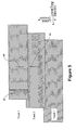
- Figure 9 illustrates a channel 0 writer-reader pair 844a, 844a geometry of a multi-channel head.
- the backward reader 854a is placed near the top edge of a previously written track n-2.
- Figure 10 illustrates the writer-reader pair geometry of channel one of the same multi-channel head shown in Figure 9.
- the backward reader 854b is positioned at the bottom edge of a previously written track of channel 1, track n-2.
- a relative position of the head may be determined. For example, data qualifying information from each channel may be compared to predetermined values to monitor and adjust the position of the head.
- This exemplary configuration and method may be extended to include all channels of a multi-channel head. All even channels may include geometry at least similar to channel 0 and all odd channels may include geometry at least similar to channel 1.
- Figure 11 illustrates an exemplary head geometry of the first four channels (0 through 3) of a multi-channel head.
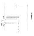
- the reverse channel read elements 1154a-d are gradually offset with respect to forward read elements 1144a-d, forward write elements 1142a-d, and adjacent data tracks n-2 to provide a more continuous indication of the head position.
- the backward read elements 1154a-d are gradually offset by small increments consecutively from each other as shown in Figure 11 .
- Figure 12 more clearly illustrates the relative position of read elements 1154a-d about their respective data tracks.
- four staggered read elements near the top edge of a track and four staggered read elements near the bottom edge of a track may be employed may a multi-channel head. It will be recognized by those of ordinary skill in the art that various other exemplary configurations of aligned or offset backward read elements may be used to provide position information to a servo system.
- a read/write head halts a read/write process at a predetermined time and a servo read element, e.g., a dedicated servo element or backward read element, is detect at least a portion of a reference data track.
- the system may register the location and/or boundaries (e.g., edges) of the reference data track relative to the active track and make adjustments to the position of the active track based on predetermined values or signals from the read head.
- the process of halting and checking the location of a reference data track may be periodically repeated as desired during writing a data track.
- Figure 13 illustrates only the relative position of head 1302 and tape 1300, however, those of ordinary skill in the art will recognize that a servo system and tape drive include numerous other features such as actuators, tape guides, rollers, reels, and the like. Such additional features have been omitted for clarity of the exemplary servo methods and systems.
- a drive servo system reads a previously written reference data track 1320 to obtain relative positional information to adjust the position of head 1302 over active track 1310 (i.e., the track being accessed for either writing or reading data).
- the system uses data integrity read signals such as Read Channel Data Validity Resources of the tape drive and signal quality metrics of servo read element 1308 positioned over reference track 1320.
- a read signal quality metric may be monitored as head 1302, including servo read head 1308, pass over reference track 1320. For a given read/write head geometry, if the relative layout of the central position and/or edges of reference track 1320 with respect to the location of active track 1310 are determined, the drive servo system can use this information to adjust the position of head 1302 over track 1310.
- the Read Channel Data Validity Resources may provide a relay type signal (ON/OFF), referred to as a "Data Valid” signal ( Figure 13 "Data Valid Signal”), representative of the ability of the read element 1306 to recover data based on any, or combination of any, of the following data validity indicators and signals:
- the lower portion of Figure 13 illustrates an exemplary read signal received from transducer head 1302 that may determine the relative position of head 402 during operation.
- the data valid signal changes its state from "OFF" near the edge of reference track 420 where data is not valid to "ON" where data is valid.
- the servo system may halt the read/write function over the active track 1310 at specified time period (Track Layout Check period: Ts as shown in Figure 13) and initiate a seek to and over the edges of reference track 1320.
- the servo system By monitoring the state of the data valid signal and instantaneous relative position of head 1302 with respect to the active track 1310 location provided by the servo position-sensing device, the servo system registers the location and boundaries of reference track 1320 relative to active track 1310. The registered values, referred to as "Reference Position,” are compared to nominal position values. If there are no substantial differences then the track layout is correct and the servo system may initiate a seek back to active track 1310 to resume read/write functions with no further action until the next Track Layout Check time Ts.
- the servo system initiates a seek back to active track 1310 and modifies the reference position of the servo positioning loop to correct the track layout back to the nominal dimensions. The system then resumes read/write functions until the next Track Layout Check time Ts.
- a dedicated read element provides a continuous read signal associated with the relative position of a reference data track with the location of the active track.
- the servo system may adjust the position of the head to a desired relative position with the reference data track based on the read signal.
- Figure 14 illustrates an exemplary system having a dedicated read element 1408 configured to provide a continuous read signal to the servo system.
- the operation of the system of Figure 14 is similar to the system of Figure 13 except that dedicated servo read element 1408 provides a continuous signal associated with the position of servo read element 1408 relative to reference track 1420.
- the servo system may make continuous position determinations and continuous adjustments to the position of head 1402. For example, as read element 1408 moves across the edge of reference track 1420, a read signal (or data valid signal) provides a linear signal proportional to the relative position of servo read element 1408 to the edge of reference track 1420.
- the read signal is used as a feed back positioning signal to enforce the tracking of the edge of reference track 1420 by the servo read element 1408.
- the design of head 1402 is such that, when servo read element 1408 tracks the edge of reference track 1420 the active read element 1406 and write element 1404 are positioned over active track 1410. Accordingly, the exemplary method supplies the servo system with a servo read signal for positioning head 1402 over desired track positions, laid out alongside and parallel to a previously written or reference track.
- One exemplary head design includes a center tapped head having two read elements, where at least one read element is a dedicated servo read element to derive servo positioning information from a reference data track.
- Figure 15 illustrates an exemplary center tapped head 1500 with two effective read elements 1532 and 1536.
- read element 1532 is configured to be positioned on the center of an active track and is approximately 0.50 track widths.
- Read element 1536 is approximately 0.8 track widths and separated 0.60 track widths away from read element 1532 by recess 1534.
- Read element 1536 is configured to be positioned on the reference track center.
- the dimensions of the second read element 1536, in this example 0.8 track widths, are at the limits of track qualifiers, which may provide for fine track positioning.
- the portion of head 1500 including read elements 1532 and 1536 includes one magneto-resistive strip.
- the electrical connections of head 700 are such that the data read element lead 1520 and the servo read element lead 1524, are independent from common lead 1522.
- Figure 16 illustrates an exemplary head 1600.
- head 1600 is center tapped with two read elements 1632 and 1636, where read element 1632 is 0.5 track widths and positioned at the center of the active track, and read element 1636 is also 0.5 track widths and separated 0.25 track widths away from read element 1632 by recess 1634.
- read element 1636 is aligned with an adjacent reference track edge and may sense track qualifiers or the like for positioning information.
- Figure 17 illustrates an exemplary head 1700.
- head 1700 is center tapped with two read elements 1732 and 1736.
- the configuration of head 1700 is similar to Figure 16 , except that recess 1734 is 0.65 track widths such that read element 1736 is configured to be aligned with the opposite or far edge of an adjacent reference track.
- Figure 18 illustrates an exemplary head 1800 with multiple taps and multiple read elements.
- Head 1800 includes three read elements 1832, 1836, and 1840 separated by recesses 1834 and 1838.
- the first read element 32 is configured to read the active track and is positioned nominally at track center.
- the second read element 1836 is positioned near a reference track edge, e.g., on the edge of track n-1 near edge n-2.
- the third read element 1840 is positioned on a second reference track, e.g., on the edge of track n-2 near n-1.
- Head 1800 may be used is a push-pull configuration with two read elements sensing servo qualifiers from the track edge at the n-1 and n-2 boundary.
- Head 1800 further includes common lead 1826 and read element lead 1828 to support read element 1840.
- Figure 19 illustrates an exemplary head 1900.
- Head 1900 includes read element 1932, which is 0.5 track widths and positioned 1.5 track widths away from the center of servo read element 1936.
- the separation formed by recess 1934 between read element 1932 and read element 1936 is 1.0 track width such that read element 1936 straddles two adjacent data tracks and may detect phase gaps between data blocks to provide relative position information.
- Figure 20 illustrates the relative geometry of a typical read-write multi-channel head using the center tapped data and servo read element.
- write elements 2005 are shown in relation to data read elements 2032 and servo read elements 2036 for one channel.
- exemplary heads and servo read element configurations are illustrative only. Various other configurations to read one or more reference tracks and provide servo information to a servo system are possible.
Landscapes
- Engineering & Computer Science (AREA)
- Manufacturing & Machinery (AREA)
- Adjustment Of The Magnetic Head Position Track Following On Tapes (AREA)
Applications Claiming Priority (4)
| Application Number | Priority Date | Filing Date | Title |
|---|---|---|---|
| US51318003P | 2003-10-20 | 2003-10-20 | |
| US513180 | 2003-10-20 | ||
| US10/928,229 US7116514B2 (en) | 2003-10-20 | 2004-08-27 | Methods and systems for magnetic recording |
| US928229 | 2004-08-27 |
Publications (1)
| Publication Number | Publication Date |
|---|---|
| EP1526514A1 true EP1526514A1 (de) | 2005-04-27 |
Family
ID=34526826
Family Applications (1)
| Application Number | Title | Priority Date | Filing Date |
|---|---|---|---|
| EP04256410A Withdrawn EP1526514A1 (de) | 2003-10-20 | 2004-10-19 | Verfahren und Systeme für magnetische Aufzeichnung |
Country Status (3)
| Country | Link |
|---|---|
| US (1) | US7116514B2 (de) |
| EP (1) | EP1526514A1 (de) |
| JP (1) | JP2005129216A (de) |
Cited By (1)
| Publication number | Priority date | Publication date | Assignee | Title |
|---|---|---|---|---|
| US9047879B2 (en) | 2013-02-26 | 2015-06-02 | International Business Machines Corporation | High performance cartridge format |
Families Citing this family (21)
| Publication number | Priority date | Publication date | Assignee | Title |
|---|---|---|---|---|
| US20040228043A1 (en) * | 2003-05-16 | 2004-11-18 | Alexander Tesler | Miniature Magnetoresistive Multitap Sensor |
| US7102845B2 (en) | 2003-10-20 | 2006-09-05 | Quantum Corporation | Servo methods and systems using existing data structures and medium edge position |
| US7085095B2 (en) * | 2003-10-20 | 2006-08-01 | Quantum Corporation | Electromagnetic void-sensing probes and position control systems |
| US7139152B2 (en) * | 2003-10-20 | 2006-11-21 | Quantum Corporation | Servo methods and systems using existing data structures and optical masks |
| US7149050B2 (en) * | 2003-10-20 | 2006-12-12 | Quantum Corporation | Diffractive position sensors and control systems |
| US7136255B2 (en) | 2003-10-20 | 2006-11-14 | Quantum Corporation | Servo methods and systems using masked medium edge position sensors |
| US7158338B2 (en) * | 2004-05-24 | 2007-01-02 | Quantum Corporation | Servo track having periodic frames of tone field and embedded synchronization marks |
| US7184233B2 (en) * | 2004-06-04 | 2007-02-27 | Quantum Corporation | Dual source tracking servo systems and associated methods |
| US7499235B2 (en) * | 2005-03-18 | 2009-03-03 | Quantum Corporation | Auto-servo tape system and associated recording head |
| US7428118B2 (en) * | 2005-11-28 | 2008-09-23 | Quantum Corporation | LTM compensation methods and systems for magnetic servo writing |
| US7826169B2 (en) * | 2007-04-25 | 2010-11-02 | Quantum Corporation | Servo error detection and compensation utilizing virtual data tracking servo methods |
| US7738212B2 (en) | 2008-02-25 | 2010-06-15 | Quantum Corporation | Methods, systems, and apparatus for reducing the effects of tape dimensional stability |
| JP2010102768A (ja) * | 2008-10-23 | 2010-05-06 | Showa Denko Kk | 垂直磁気記憶媒体および磁気記憶装置 |
| US8514675B2 (en) | 2011-05-11 | 2013-08-20 | Oracle International Corporation | Suspension system for an optical pickup assembly |
| US9251828B2 (en) * | 2011-09-29 | 2016-02-02 | International Business Machines Corporation | Servo control |
| US8773806B2 (en) | 2012-02-08 | 2014-07-08 | Lsi Corporation | Disk-based storage device with head position control responsive to detected inter-track interference |
| US8711517B2 (en) * | 2012-04-27 | 2014-04-29 | Seagate Technology Llc | Two dimensional magnetic sensor immune to skew angle misalignment |
| US8913345B1 (en) * | 2012-08-29 | 2014-12-16 | Marvell International Ltd. | System and method for reading data from a magnetic medium by utilizing plural read sensors which define an effective read width |
| US9336812B1 (en) | 2015-01-09 | 2016-05-10 | Oracle International Corporation | Adaptive control of tracking servo system of optical heads in optical storage devices |
| US9911443B2 (en) | 2015-02-27 | 2018-03-06 | International Business Machines Corporation | Aligned shingled writing for magnetic recording media and media having shingle edge positioned tracks |
| US9613646B2 (en) | 2015-03-06 | 2017-04-04 | International Business Machines Corporation | Measurement and correction of magnetic writer offset error |
Citations (9)
| Publication number | Priority date | Publication date | Assignee | Title |
|---|---|---|---|---|
| JPS59185020A (ja) * | 1982-12-10 | 1984-10-20 | Sony Corp | テ−プレコ−ダ |
| US4866548A (en) * | 1986-12-22 | 1989-09-12 | Tandberg Data A/S | Method and arrangement for precise positioning of a magnetic head to various tracks of a magnetic tape |
| US5289328A (en) * | 1992-05-26 | 1994-02-22 | George Saliba | Method and apparatus for variable density read-after-writing on magnetic tape |
| US5371638A (en) * | 1992-06-24 | 1994-12-06 | Digital Equipment Corporation | Servo method and apparatus for very high track density magnetic recording by adjusting head position based on servo information read from adjacent track |
| US5452152A (en) * | 1990-08-28 | 1995-09-19 | Tandberg Data A/S | Tracking control on longitudinal azimuth tracks using an auxiliary read head |
| US5523904A (en) * | 1992-06-24 | 1996-06-04 | Quantum Corporation | Linear tape write servo using embedded azimuth servo blocks |
| EP0919990A2 (de) * | 1997-11-24 | 1999-06-02 | Hewlett-Packard Company | Fähigkeit zum Lesen/Schreiben von Bändern älterer Generationen im longitudinalen Aufzeichnungsmodus durch Ausschneiden von Spuren |
| US6108159A (en) * | 1997-07-14 | 2000-08-22 | Quantum Corporation | Data track edge follower servo method and apparatus |
| US20020176200A1 (en) * | 2001-05-24 | 2002-11-28 | Hitesh Trivedi | Magnetic track following servo algorithm using signal quality |
Family Cites Families (94)
| Publication number | Priority date | Publication date | Assignee | Title |
|---|---|---|---|---|
| US2937239A (en) * | 1956-02-13 | 1960-05-17 | Gen Electric | Skew servo for multiple channel recording system |
| US3633038A (en) * | 1970-05-01 | 1972-01-04 | Newell Ind | Transducer-positioning system using radiation-sensitive means |
| US3829895A (en) * | 1970-08-17 | 1974-08-13 | Matsushita Electric Industrial Co Ltd | Multi-channel magnetic head with offset gap lines |
| FR2235448B1 (de) * | 1973-06-29 | 1976-05-07 | Thomson Brandt | |
| US4056830A (en) * | 1974-03-15 | 1977-11-01 | Burroughs Corporation | Utilizing data for transducer positioning |
| US3919697A (en) * | 1974-06-26 | 1975-11-11 | Battelle Development Corp | Data record tracking using track identifying information in the gaps between recorded data groups |
| NL7600470A (nl) * | 1976-01-17 | 1977-07-19 | Philips Nv | Servosysteem voor het sturen van de positie van een magneetkop ten opzichte van een te volgen spoor. |
| US4149204A (en) * | 1977-03-28 | 1979-04-10 | International Business Machines Corporation | Minor bit reduction on a magnetic head |
| US4502082A (en) * | 1977-06-16 | 1985-02-26 | Burroughs Corporation | Spiral recording and associated system |
| FR2405536A1 (fr) * | 1977-10-07 | 1979-05-04 | Thomson Csf | Dispositif d'enregistrement-lecture d'une information sur une boucle de ruban magnetique enroule dans une cassette sans fin |
| NL7712418A (nl) * | 1977-11-11 | 1979-05-15 | Philips Nv | Opteken- en/of weergeefinrichting voor een bandvormige magnetische registratiedrager voor- zien van een regelsysteem voor de positionering van de magneetkop. |
| JPS55125530A (en) * | 1979-03-20 | 1980-09-27 | Mitsubishi Electric Corp | Magnetic recorder/reproducer |
| NL7907219A (nl) * | 1979-09-28 | 1981-03-31 | Philips Nv | Apparaat voor het opnemen en/of weergeven van op een magneetband in een aantal parallele, longitudinale sporen opgenomen magnetische signalen. |
| JPS56124103A (en) * | 1980-02-29 | 1981-09-29 | Victor Co Of Japan Ltd | Digital magnetic recording and/or reproducing method |
| JPS576433A (en) * | 1980-06-13 | 1982-01-13 | Toshiba Corp | Magnetic recorder and reproducer |
| JPS57186229A (en) * | 1981-05-11 | 1982-11-16 | Mitsubishi Electric Corp | Magnetic head for azimuth recording |
| US4539615A (en) * | 1981-06-08 | 1985-09-03 | Hitachi, Ltd. | Azimuthal magnetic recording and reproducing apparatus |
| US4472750A (en) * | 1981-07-02 | 1984-09-18 | Irwin Magnetic Systems, Inc. | Data record with pre-recorded transducer positioning signals, and system for utilizing same |
| US4439793A (en) * | 1981-10-22 | 1984-03-27 | Fuji Photo Film Co., Ltd. | Thin film head array |
| US4414589A (en) * | 1981-12-14 | 1983-11-08 | Northern Telecom Inc. | Embedded servo track following system and method for writing servo tracks |
| US4449082A (en) * | 1981-12-17 | 1984-05-15 | Webster Douglas G | Motor speed control system |
| US4685005A (en) * | 1983-07-18 | 1987-08-04 | International Business Machines Corporation | Two-module-read, read-after-write, bi-directional tape drive |
| EP0190555B1 (de) * | 1985-02-08 | 1989-01-18 | Tandberg Data A/S | Verfahren und Anordnung zum Positionieren eines Magnetkopfs auf verschiedene Spuren eines Magnetbands |
| US4802030A (en) * | 1986-06-25 | 1989-01-31 | Hewlett-Packard Company | Head-tape alignment apparatus with a tape edge find operation |
| US4816939A (en) * | 1986-08-21 | 1989-03-28 | Polaroid Corporation | Magnetic recording media and servo systems using light-transmitting optical gratings |
| US4979051A (en) * | 1988-03-22 | 1990-12-18 | Eggebeen James A | Bimodal multi-track magnetic head |
| US4975791A (en) * | 1988-03-22 | 1990-12-04 | Carlisle Memory Products Group Incorporated | Recording system having head transducers with controlled skew |
| KR930001151B1 (ko) * | 1988-07-11 | 1993-02-19 | 마쓰시다 덴끼 산교오 가부시기가이샤 | 자기 기록 재생장치 |
| US5285331A (en) * | 1989-02-23 | 1994-02-08 | Wangtek Incorporated | System for aligning a read head gap over a track of magnetic data |
| JPH02297702A (ja) * | 1989-05-11 | 1990-12-10 | Teac Corp | ディスク装置 |
| US5257148A (en) * | 1989-05-30 | 1993-10-26 | Tandberg Data As | Method and apparatus for positioning a magnetic head in a magnetic layer memory system using tracking by reading a spaced pair of corresponding subtracks |
| US5050017A (en) * | 1989-08-23 | 1991-09-17 | Eastman Kodak Company | Memory guided magnetic tape tracking |
| US5121270A (en) * | 1989-09-19 | 1992-06-09 | Alcudia Ezra R | Multitransducer head positioning servo for use in a bi-directional magnetic tape system |
| US5132861A (en) * | 1989-10-02 | 1992-07-21 | Behr Michael I | Systems using superimposed, orthogonal buried servo signals |
| US5055959A (en) * | 1990-01-09 | 1991-10-08 | Digital Equipment Corporation | Tape head with low spacing loss produced by narrow and wide wear regions |
| US5262908A (en) * | 1990-02-20 | 1993-11-16 | Sharp Kabushiki Kaisha | Tracking control device for magnetic recording/reproducing apparatus |
| JPH03290816A (ja) * | 1990-04-06 | 1991-12-20 | Sony Corp | 記録再生装置及びその記録媒体 |
| US5563868A (en) * | 1990-06-18 | 1996-10-08 | Matsushita-Kotobuki Electronics Industries, Ltd. | Optical servo system for magnetic disk |
| US5617269A (en) * | 1991-12-23 | 1997-04-01 | Conner Peripherals, Inc. | System for recording track-centering servo signals on multi-track magnetic medium |
| US5294803A (en) * | 1991-12-30 | 1994-03-15 | Tandberg Data A/S | System and a method for optically detecting an edge of a tape |
| US5949604A (en) * | 1992-06-24 | 1999-09-07 | Quantum Corporation | Method of writing and reading servo on tracks having a longitudinal gap |
| US5426551A (en) * | 1993-07-19 | 1995-06-20 | Quantum Corp. | Magnetic contact head having a composite wear surface |
| US5448430A (en) * | 1993-08-05 | 1995-09-05 | International Business Machines Corporation | Track following servo demodulation |
| US5600505A (en) * | 1994-06-10 | 1997-02-04 | Exabyte Corporation | Skew correction in a multi-track tape recorder/player |
| US5600500A (en) * | 1994-11-14 | 1997-02-04 | Seagate Technology, Inc. | Performance based write current optimization process |
| US5815337A (en) * | 1995-10-24 | 1998-09-29 | Seagate Technology, Inc. | Tape drive having an arcuate scanner and a method for calibrating the arcuate scanner |
| EP1316946A3 (de) * | 1995-11-13 | 2004-10-27 | Quantum Corporation | Vorrichtung zur Justierung des Zenithwinkels für Köpfe in Bandlaufwerken |
| US6130792A (en) * | 1995-11-13 | 2000-10-10 | Seagate Technology, Inc. | Flat servo bursts for arcuate track scanner |
| US5847892A (en) * | 1995-11-13 | 1998-12-08 | Seagate Technology, Inc. | Servoing and formatting magnetic recording tape in an arcuate scanner system |
| US5796537A (en) * | 1995-11-13 | 1998-08-18 | Seagate Technology, Inc. | Method and arrangement for servoing and formatting magnetic recording tape |
| US5862014A (en) * | 1996-01-11 | 1999-01-19 | Quantum Corporation | Multi-channel magnetic tape head module including flex circuit |
| US5867339A (en) * | 1996-01-11 | 1999-02-02 | Quantum Corporation | Two channel azimuth and two channel non-azimuth read-after-write longitudinal magnetic head |
| US5588007A (en) | 1996-04-26 | 1996-12-24 | Iomega Corporation | Method for detecting transient write errors in a disk drive |
| US5940238A (en) * | 1996-06-07 | 1999-08-17 | Seagate Technology, Inc. | Mechanism to reduce adjacent track interference in a magnetic tape data storage system |
| TW326092B (en) * | 1996-06-28 | 1998-02-01 | Thomson Brandt Gmbh | Multitrack tape device using a movable magnetic head with a planar surface and comprising tape supporting means |
| US5844814A (en) | 1996-09-27 | 1998-12-01 | International Business Machines Corporation | Optical position sensing device and method for sub-micron measurement |
| US5757575A (en) * | 1996-10-31 | 1998-05-26 | Ampex Corporation | Track-curvature detection using clock phase shift in azimuth recording |
| US6018434A (en) * | 1997-01-14 | 2000-01-25 | Quantum Corporation | Tape cartridge having written-in-defect servo patterns for rapid head position calibration |
| US5872675A (en) | 1997-01-21 | 1999-02-16 | Tandberg Data Asa | Tape cartridge with integrated mirror tracking mechanism |
| US5973872A (en) * | 1997-01-23 | 1999-10-26 | Quantum Corporation | Method and apparatus for a low cost multi-channel tape recording head |
| US6185063B1 (en) * | 1997-02-13 | 2001-02-06 | Seagate Technology Llc | Methods and apparatus for overlapping data tracks on a storage medium |
| US6134072A (en) * | 1997-03-26 | 2000-10-17 | Exabyte Corporation | Tracking of non-native stripes in helical scan tape drive |
| US6005737A (en) | 1997-05-24 | 1999-12-21 | Seagate Technology, Inc. | Magnetic tape drive having improved servo control |
| US5982711A (en) * | 1997-06-05 | 1999-11-09 | Hewlett-Packard Co. | Device for reading data from or writing data to magnetic storage media and a method of positioning a tape head relative to the magnetic storage media |
| US6118605A (en) * | 1997-11-25 | 2000-09-12 | Storage Technology Corporation | System for gap positioning optimization in a tape drive |
| US6084740A (en) * | 1997-12-01 | 2000-07-04 | Storage Technology Corporation | Optical servo system for a tape drive |
| JPH11176118A (ja) * | 1997-12-16 | 1999-07-02 | Mitsubishi Electric Corp | 磁気記録装置 |
| US6075678A (en) * | 1998-03-24 | 2000-06-13 | Quantum Corporation | Pivoting lever cam guide tape head positioner |
| GB2335785B (en) * | 1998-03-24 | 2002-09-18 | Quantum Corp | Multi-channel magnetic tape system having optical tracking servo |
| US6275350B1 (en) * | 1998-04-03 | 2001-08-14 | Hewlett-Packard Company | Magnetic head and method for compensating for magnetic tape dimensional instability |
| US6222698B1 (en) * | 1998-05-22 | 2001-04-24 | Hewlett-Packard Company | Magnetic tape dimensional instability compensation by varying recording head azimuth angle |
| US6088184A (en) * | 1998-06-16 | 2000-07-11 | International Business Machines Corporation | Apparatus and method for the control and positioning of magnetic recording heads in an azimuth recording system |
| US6141174A (en) * | 1998-08-14 | 2000-10-31 | Quantum Corporation | Method of reading recorded information from a magnetic tape that compensates for track pitch changes |
| US6188532B1 (en) | 1998-09-08 | 2001-02-13 | Quantum Corporation | Backward compatible head and head positioning assembly for a linear digital tape drive |
| DE19846835A1 (de) | 1998-10-10 | 2000-04-13 | Thomson Brandt Gmbh | Verfahren zur Spurlageregelung |
| US6246535B1 (en) * | 1998-11-13 | 2001-06-12 | Quantum Corporation | Optical apparatus for tracking a magnetic tape |
| US6275349B1 (en) * | 1998-12-02 | 2001-08-14 | Storage Technology Corporation | Integrated optical tracking system for magnetic media |
| US6433951B1 (en) * | 1999-02-17 | 2002-08-13 | Imation Corp. | Magnetic data storage tape with etched servo pattern, method of manufacturing same, and method of servo positioning on same |
| US6366422B1 (en) * | 1999-04-01 | 2002-04-02 | Storage Technology Corporation | Helical scan tape drive error recovery using track profile mapping |
| US6545837B1 (en) * | 1999-12-21 | 2003-04-08 | Imation Corp. | Method and apparatus for servo controlled azimuth data recording |
| US6493174B1 (en) | 2000-02-17 | 2002-12-10 | Imation Corp. | Optical servo system for use with magnetic data storage tape having magnetic reference indicators |
| US6339522B1 (en) * | 2000-05-11 | 2002-01-15 | Tandberg Data Asa | Magnetic data transfer system with dynamic head-to-tape alignment |
| US6512651B1 (en) * | 2000-07-11 | 2003-01-28 | Storage Technology Corporation | Helical scan tape track following |
| US6700729B1 (en) * | 2000-10-17 | 2004-03-02 | Hewlett-Packard Development Company | Alignment marks for tape head positioning |
| US6570731B2 (en) * | 2001-05-14 | 2003-05-27 | Quantum Corporation | System for detecting an edge of a moving data storage medium |
| US7149049B2 (en) * | 2001-06-07 | 2006-12-12 | Quantum Corporation | Optical apparatus for tracking a magnetic tape |
| US6856484B2 (en) * | 2001-09-05 | 2005-02-15 | Quantum Corporation | Magnetic servo of a recording head |
| US6775092B2 (en) * | 2001-12-07 | 2004-08-10 | Quantum Corporation | Lateral tape motion sensor |
| US6801383B2 (en) * | 2002-04-04 | 2004-10-05 | Quantum Corporation | Method for calibrating a tape media using staggered calibration tracks |
| US7136255B2 (en) * | 2003-10-20 | 2006-11-14 | Quantum Corporation | Servo methods and systems using masked medium edge position sensors |
| US7102845B2 (en) * | 2003-10-20 | 2006-09-05 | Quantum Corporation | Servo methods and systems using existing data structures and medium edge position |
| US7139152B2 (en) * | 2003-10-20 | 2006-11-21 | Quantum Corporation | Servo methods and systems using existing data structures and optical masks |
| US7149050B2 (en) * | 2003-10-20 | 2006-12-12 | Quantum Corporation | Diffractive position sensors and control systems |
| US7085095B2 (en) * | 2003-10-20 | 2006-08-01 | Quantum Corporation | Electromagnetic void-sensing probes and position control systems |
-
2004
- 2004-08-27 US US10/928,229 patent/US7116514B2/en not_active Expired - Fee Related
- 2004-10-19 EP EP04256410A patent/EP1526514A1/de not_active Withdrawn
- 2004-10-19 JP JP2004304649A patent/JP2005129216A/ja active Pending
Patent Citations (9)
| Publication number | Priority date | Publication date | Assignee | Title |
|---|---|---|---|---|
| JPS59185020A (ja) * | 1982-12-10 | 1984-10-20 | Sony Corp | テ−プレコ−ダ |
| US4866548A (en) * | 1986-12-22 | 1989-09-12 | Tandberg Data A/S | Method and arrangement for precise positioning of a magnetic head to various tracks of a magnetic tape |
| US5452152A (en) * | 1990-08-28 | 1995-09-19 | Tandberg Data A/S | Tracking control on longitudinal azimuth tracks using an auxiliary read head |
| US5289328A (en) * | 1992-05-26 | 1994-02-22 | George Saliba | Method and apparatus for variable density read-after-writing on magnetic tape |
| US5371638A (en) * | 1992-06-24 | 1994-12-06 | Digital Equipment Corporation | Servo method and apparatus for very high track density magnetic recording by adjusting head position based on servo information read from adjacent track |
| US5523904A (en) * | 1992-06-24 | 1996-06-04 | Quantum Corporation | Linear tape write servo using embedded azimuth servo blocks |
| US6108159A (en) * | 1997-07-14 | 2000-08-22 | Quantum Corporation | Data track edge follower servo method and apparatus |
| EP0919990A2 (de) * | 1997-11-24 | 1999-06-02 | Hewlett-Packard Company | Fähigkeit zum Lesen/Schreiben von Bändern älterer Generationen im longitudinalen Aufzeichnungsmodus durch Ausschneiden von Spuren |
| US20020176200A1 (en) * | 2001-05-24 | 2002-11-28 | Hitesh Trivedi | Magnetic track following servo algorithm using signal quality |
Non-Patent Citations (1)
| Title |
|---|
| PATENT ABSTRACTS OF JAPAN vol. 009, no. 048 (P - 338) 28 February 1985 (1985-02-28) * |
Cited By (2)
| Publication number | Priority date | Publication date | Assignee | Title |
|---|---|---|---|---|
| US9047879B2 (en) | 2013-02-26 | 2015-06-02 | International Business Machines Corporation | High performance cartridge format |
| US9437241B2 (en) | 2013-02-26 | 2016-09-06 | International Business Machines Corporation | High performance cartridge format |
Also Published As
| Publication number | Publication date |
|---|---|
| JP2005129216A (ja) | 2005-05-19 |
| US7116514B2 (en) | 2006-10-03 |
| US20050083600A1 (en) | 2005-04-21 |
Similar Documents
| Publication | Publication Date | Title |
|---|---|---|
| US7116514B2 (en) | Methods and systems for magnetic recording | |
| US7889454B2 (en) | Distributed servo patterns for data storage media | |
| US6943979B2 (en) | Method and apparatus for written-in tracking error composition for linear tape drives | |
| US7652841B2 (en) | Servo controlling method, recording/reproducing apparatus, magnetic tape, and magnetic tape cartridge | |
| US7139152B2 (en) | Servo methods and systems using existing data structures and optical masks | |
| US9324349B2 (en) | Magnetic data storage apparatus for use with linear recording media having a reduced servo band width | |
| US20090279202A1 (en) | Head design for writing servo patterns on magnetic tape | |
| US20060103968A1 (en) | Dynamic skew compensation systems and associated methods | |
| JP2006099919A (ja) | 磁気テープの記録再生方法および記録再生装置 | |
| US20060092547A1 (en) | Method and a device for recording and reproducing data onto and from a magnetic tape | |
| US7649707B2 (en) | Auto-servo tape system and associated recording head | |
| US6172837B1 (en) | Postponable servo code selection | |
| US7199958B2 (en) | Servo head with varying write gap width | |
| US7102845B2 (en) | Servo methods and systems using existing data structures and medium edge position | |
| US7495859B2 (en) | Interleaved servo pattern | |
| US7038871B2 (en) | Multi-band servo patterns with inherent track ID | |
| US11605399B2 (en) | High-precision servo system for advanced magnetic tape storage system | |
| US7881008B2 (en) | Joint specification of servo format and servo reader parameters for tape drive systems | |
| US7184233B2 (en) | Dual source tracking servo systems and associated methods | |
| JP4066376B2 (ja) | 磁気テープの記録再生方法 | |
| US6906881B2 (en) | Apparatus and method to erase a magnetic tape | |
| JPH08249635A (ja) | テープ走行装置 |
Legal Events
| Date | Code | Title | Description |
|---|---|---|---|
| PUAI | Public reference made under article 153(3) epc to a published international application that has entered the european phase |
Free format text: ORIGINAL CODE: 0009012 |
|
| AK | Designated contracting states |
Kind code of ref document: A1 Designated state(s): AT BE BG CH CY CZ DE DK EE ES FI FR GB GR HU IE IT LI LU MC NL PL PT RO SE SI SK TR |
|
| AX | Request for extension of the european patent |
Extension state: AL HR LT LV MK |
|
| 17P | Request for examination filed |
Effective date: 20051020 |
|
| AKX | Designation fees paid |
Designated state(s): DE GB |
|
| 17Q | First examination report despatched |
Effective date: 20070820 |
|
| STAA | Information on the status of an ep patent application or granted ep patent |
Free format text: STATUS: THE APPLICATION IS DEEMED TO BE WITHDRAWN |
|
| 18D | Application deemed to be withdrawn |
Effective date: 20110503 |