EP1526540A1 - Dispositif et procédé de recherche de positions initiales de reproduction pour magnétoscope - Google Patents
Dispositif et procédé de recherche de positions initiales de reproduction pour magnétoscope Download PDFInfo
- Publication number
- EP1526540A1 EP1526540A1 EP04021834A EP04021834A EP1526540A1 EP 1526540 A1 EP1526540 A1 EP 1526540A1 EP 04021834 A EP04021834 A EP 04021834A EP 04021834 A EP04021834 A EP 04021834A EP 1526540 A1 EP1526540 A1 EP 1526540A1
- Authority
- EP
- European Patent Office
- Prior art keywords
- snapshot
- broadcast signals
- images
- playback
- videotape
- Prior art date
- Legal status (The legal status is an assumption and is not a legal conclusion. Google has not performed a legal analysis and makes no representation as to the accuracy of the status listed.)
- Withdrawn
Links
- 238000000034 method Methods 0.000 title claims description 17
- 239000011159 matrix material Substances 0.000 claims abstract description 14
- 238000001514 detection method Methods 0.000 claims description 6
- 230000009191 jumping Effects 0.000 abstract description 4
- 230000005236 sound signal Effects 0.000 description 7
- 239000002131 composite material Substances 0.000 description 5
- 230000006870 function Effects 0.000 description 5
- 239000000284 extract Substances 0.000 description 4
- 238000007796 conventional method Methods 0.000 description 2
- 238000010586 diagram Methods 0.000 description 2
- 230000005540 biological transmission Effects 0.000 description 1
- 238000006243 chemical reaction Methods 0.000 description 1
- 238000012986 modification Methods 0.000 description 1
- 230000004048 modification Effects 0.000 description 1
- 238000013139 quantization Methods 0.000 description 1
Images


Classifications
-
- G—PHYSICS
- G11—INFORMATION STORAGE
- G11B—INFORMATION STORAGE BASED ON RELATIVE MOVEMENT BETWEEN RECORD CARRIER AND TRANSDUCER
- G11B27/00—Editing; Indexing; Addressing; Timing or synchronising; Monitoring; Measuring tape travel
- G11B27/10—Indexing; Addressing; Timing or synchronising; Measuring tape travel
-
- G—PHYSICS
- G11—INFORMATION STORAGE
- G11B—INFORMATION STORAGE BASED ON RELATIVE MOVEMENT BETWEEN RECORD CARRIER AND TRANSDUCER
- G11B27/00—Editing; Indexing; Addressing; Timing or synchronising; Monitoring; Measuring tape travel
- G11B27/10—Indexing; Addressing; Timing or synchronising; Measuring tape travel
- G11B27/11—Indexing; Addressing; Timing or synchronising; Measuring tape travel by using information not detectable on the record carrier
-
- G—PHYSICS
- G11—INFORMATION STORAGE
- G11B—INFORMATION STORAGE BASED ON RELATIVE MOVEMENT BETWEEN RECORD CARRIER AND TRANSDUCER
- G11B2220/00—Record carriers by type
- G11B2220/90—Tape-like record carriers
Definitions
- the present invention relates to a video cassette recorder system; and more particularly, to an apparatus and a method for searching for playback start positions, included in a video cassette recorder system, to thereby replay recorded broadcast signals from the playback start positions, conveniently.
- VCR Video Cassette Recorder
- VISS Video Home System Index Search System
- a mode of a VCR system should be set to a stop mode through user manipulations, and after VISS signals are recorded, the mode of the VCR system should be changed to a playback mode. Therefore, there is a problem in that a series of the user manipulations are very inconvenient.
- VISS signals recorded on the videotape are searched for by pressing index (VISS) buttons and then the mode of the VCR system should be returned to the playback mode through user manipulation, so that there is also a problem in that the user manipulations are inconvenient.
- VISS pressing index
- an object of the present invention to provide an apparatus and a method for searching for playback start positions, to thereby replay broadcast signals recorded on a videotape from a wanted playback start position, automatically, in a VCR system having a built-in digital tuner for receiving broadcast signals.
- an apparatus for replaying broadcast signals, which are recorded on a videotape, from a wanted playback start position selected by a user included in a Video Cassette Recorder (VCR) system, including: means for storing snapshot images, generated by extracting still images from the broadcast signals at predetermined intervals, when the broadcast signals are recorded on the videotape, and retrieving the stored snapshot images to construct a snapshot set screen by arranging the retrieved snapshot images in an N ⁇ N or an N ⁇ M matrix form and providing the snapshot set screen to a display unit, when a detection of the wanted playback start position is requested; means for comparing playback signals generated by replaying the broadcast signals recorded on the videotape with a specific snapshot image, which is corresponding to the wanted playback start position, to thereby detect a section of the playback signals corresponding to the specific snapshot image, in case the specific snapshot image is selected among the snapshot images on the snapshot set screen which is provided to the display unit; and means for replaying the broadcast signals recorded
- VCR Video Cassette Recorder
- an apparatus for replaying broadcast signals, which are recorded on a videotape, from a wanted playback start position selected by a user, included in a VCR system including: means for generating snapshot images by extracting still images from the broadcast signals at predetermined intervals when the broadcast signals are recorded on the videotape, and then for storing the snapshot images; means for retrieving the stored snapshot images to construct a snapshot set screen by arranging the retrieved snapshot images in an N ⁇ N or an N ⁇ M matrix form and providing the snapshot set screen to a display unit, when a detection of the wanted playback start position is requested; means for commanding a high-speed rewind mode or a high-speed playback mode of the broadcast signals recorded on the videotape to generate high-speed playback broadcast signals, in case the broadcast signals are required to be replayed from a specific snapshot image by selecting the specific snapshot image among the snapshot images on the snapshot set screen which is provided to the display unit; means for comparing the high-speed playback broadcast signals
- a method of replaying broadcast signals, which are recorded on a videotape, from a wanted playback start position selected by a user, included in a VCR system including the steps of: storing snapshot images, generated by extracting still images from the broadcast signals at predetermined intervals, when the broadcast signals are recorded on the videotape; retrieving the stored snapshot images to construct a snapshot set screen by arranging the retrieved snapshot images in an NxN or an NxM matrix form and providing the snapshot set screen to a display unit, when a detection of the wanted playback start position is required; selecting a specific snapshot image, which is corresponding to the wanted playback start position among the snapshot images on the snapshot set screen which is provided to the display unit; comparing playback signals generated by replaying the broadcast signals recorded on the videotape with the specific snapshot image, to thereby detect a section of the playback signals corresponding to the specific snapshot image; and replaying the broadcast signals recorded on the videotape from the detected section; wherein the N and
- a plurality of snapshot images i.e., still images of broadcast signals which are being recorded on a videotape, are stored in a memory area at regular intervals in the course of recording the broadcast signals on the videotape, and then, when a user requests a search for a wanted playback start position, (a request for a snapshot), a snapshot set screen, on which the still images stored at regular intervals are arranged in an NxN or an NxM matrix form, is provided to a display unit, and then, when a specific snapshot image (or a jump image), which corresponds to the wanted playback start position, on the snapshot set screen is selected by the user to replay the broadcast signals from the wanted playback start position, a playback mode is automatically performed by jumping to the specific snapshot image.
- the N and the M denote positive integral numbers, that is, natural numbers.
- Fig. 1 is a block diagram showing a VCR system including an apparatus for searching for playback start positions in accordance with a preferred embodiment of the present invention.
- the VCR system having a built-in digital tuner includes a tuner and demodulation block 102, a demultiplexer 104, a Moving Picture Experts Group (MPEG) decoding block 106, an encoding block 108, an output switching block 110, a control block 112, a first memory block 114, a second memory block 116, a menu generation block 118, a VCR control block 120, and a recording and playback block 122.
- MPEG Moving Picture Experts Group
- the tuner and demodulation block 102 extracts additional information (that is, channel information packet data, program information packet data, etc.) from data streams received through a cable (not shown).
- the tuner and demodulation block 102 extracts (1) channel information packet data that includes Program Allocation Table (PAT) information composed of N-bit Program Identifier (PID) information indicating the program numbers for each broadcast channel, and (2) program information packet data that includes Program Map Table (PMT) information composed of N-bit PID information indicating audio, video and text of a specific channel, N-bit detailed PID information indicating the detailed information on each program, program information of each channel, and the like.
- PAT Program Allocation Table
- PMT Program Map Table
- the extracted channel information packet data and the extracted program information packet data are provided to the control block 112 (which will be described later) through a line L11 after passing through processes, such as conversion into an intermediate frequency, demodulation, error correction and the like.
- the channel information packet data and the program information packet data provided to the control block 112 through the line L11 are used to tune a specific channel when the specific channel is selected by the user, thus allowing the control block 112 to generate a tuning control signal. Further, the channel information packet data and the program information packet data are used as the contents of a menu screen when the display of a plurality of pieces of channel information and the program information of each channel is requested by the user.
- the demultiplexer 104 selects broadcast signals of one cable broadcasting station among demodulated broadcast signals of a plurality of cable broadcasting stations provided from the tuner and the demodulation block 102, on the basis of the tuning control signal provided from the control block 112 through a line L12, and then transmits the selected broadcast signals to the MPEG decoding block 106.
- the MPEG decoding block 106 restores the selected broadcast signals, i.e., compression-coded audio and video signals (the audio and video signals compression-coded in view of time and space correlation), which are provided from the demultiplexer 104, into original signals by adopting decoding techniques, such as variable-length decoding, inverse Discrete Cosine Transform (DCT), inverse quantization, motion compensation and the like, based on a decoding control signal provided by the control block 112 through a line L13.
- decoding techniques such as variable-length decoding, inverse Discrete Cosine Transform (DCT), inverse quantization, motion compensation and the like, based on a decoding control signal provided by the control block 112 through a line L13.
- the restored digital video and audio signals are provided to the encoding block 108.
- the encoding block 108 converts the digital video and audio signals, provided from the MPEG decoding block 106, into National Television System Committee (NTSC)-or Phase Alternation by Line system (PAL)- type analog video and audio signals on the basis of an encoding control signal provided from the control block 112 through a line L14, and then provides the analog video and audio signals to the output switching block 110.
- NSC National Television System Committee
- PAL Phase Alternation by Line system
- the encoding block 108 provides the analog broadcast signals to the control block 112 through the line L14 to collect the snapshot images for high-speed searches for playback start positions.
- each of the still images can be provided to the control block 112 at predetermined regular intervals, or each of the still images can be provided to the control block 112 whenever the control block 112 requests a transmission of the still images.
- control block 112 which includes, for example, a microprocessor for controlling the entire operation of the system, etc., generates a tuning control signal corresponding to the channel information packet data and the program information packet data when the channel information packet data and the program information packet data are inputted thereto, and then provides the tuning control signal to the tuner and demodulation block 102 and the demultiplexer 104 through the lines L11 and L12, respectively. Further, the control block 112 sequentially stores the channel information packet data and the program information packet data for each channel in a predetermined area of the first memory block 114.
- control block 112 retrieves the channel information packet data and the program information packet data for each channel which have been stored in the predetermined area of the first memory block 114, and then provides the channel information packet data and program information packet data to the menu generation block 118 through a line L15.
- control block 112 when a user manipulation signal for recording the broadcast signals on a videotape or playing a program recorded on the videotape is inputted to the control block 112, the control block 112 generates a recording or playback control signal corresponding to the user manipulation signal, and then transmits the recording or playback control signal to the VCR control block 120 through a line L16.
- the control block 112 extracts the still images from the broadcast signals, which are provided from the encoding block 108 through the line L14, at regular intervals (e.g., 30 sec, 1 min, 2 min or 4 min) or directly receives the still images, which are generated in the encoding block 108, through the line L14 at regular intervals, so as to collect the snapshot images for high-speed searches for playback start positions.
- the control block 112 indexes each of the still images sequentially, and then constructs a snapshot set screen by arranging the indexed still images (the indexed snapshot images) in an N ⁇ N or an N ⁇ M matrix form, and then stores data of the snapshot set screen in the second memory block 116.
- the data of the snapshot set screen are used as index information for searching for the playback start positions chosen by the user.
- the control block 112 commands the VCR control block 120 to perform a high-speed rewind mode or a high-speed playback mode for the search for the playback start position (or the jump position) through the line L16.
- the control block 112 when high-speed playback broadcast signals, which are replayed in the high-speed rewind mode or the high-speed playback mode, are inputted from the VCR control block 120 to the control block 112 through a line L17, if the high-speed playback broadcast signals corresponding to the specific snapshot image is detected, the control block 112 generates a jump playback command signal for commanding a playback operation from the jump position and then transmits the jump playback command signal to the VCR control block 120 through the line L16. As a result, the VCR control block 120 performs the playback mode from the jump position.
- the menu generation block 118 constructs the channel information packet data and the program information packet data for each channel, which are provided from the control block 112 through the line L15, into menu screen data using graphics, and then converts the constructed menu screen data into NTSC or PAL analog signals, and then provides the NTSC or PAL analog signals to the output switching block 110.
- the output switching block 110 transmits the analog video and audio signals provided from the encoding block 108 to a display unit and a speaker, and, in case of recording mode, transmits the analog video and audio signals to the VCR control block 120.
- a recording operation is not performed through the line L19, but the video signals transmitted to the display unit are displayed in the form of composite screen data, i.e., the combination of the menu screen data, provided from the menu generation block 118, and the video signals.
- the VCR control block 120 includes, for example, a microprocessor, etc., to control the entire operation of the VCR.
- the VCR control block 120 converts broadcast signals (analog video and audio signals) provided through the output switching block 110 into signals recordable on a videotape and then transmits the recordable signals to the recording and playback block 122.
- the VCR control block 120 transmits playback signals provided from the recording and playback block 122 to the output switching block 110.
- the VCR control block 120 transmits the high-speed playback broadcast signals, which are replayed by performing the high-speed rewind mode or the high-speed playback mode, to the control block 112 through the line L17.
- the high-speed playback broadcast signals provided to the control block 112 are used to search for the specific snapshot image, i.e., the wanted playback start position (the jump position) on the N ⁇ N or the N ⁇ M matrix-form snapshot set screen.
- the recording and playback block 122 including a head drum, a deck for accommodating the videotape, etc., performs a function of amplifying the recordable broadcast signals, provided from the VCR control block 120, to a certain level and then recording the amplified broadcast signals on the videotape, in the recording mode, and a function of detecting the playback signals replayed from the videotape and then transmitting the playback signals to the VCR control block 120 in the playback mode, and a function of transmitting the high-speed playback broadcast signals to the VCR control block 120 in the high-speed rewind mode or the high-speed playback mode.
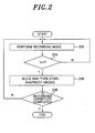
- Fig. 2 is a flowchart showing a process of storing snapshot images during a recording operation of a VCR system to search for playback start positions in accordance with the present invention.
- a recording mode in which analog broadcast signals generated by tuning, decoding and encoding the broadcast signals sequentially are recorded on a videotape, is performed under the control of the control block 112 (step 202).
- control block 112 extracts still images at predetermined regular intervals and then indexes each of the still images, to thereby construct an N ⁇ N or an N ⁇ M matrix-form snapshot set screen, and then stores data of the snapshot set screen in a second memory block 116 (steps 204, 206).
- the collection of the still images is implemented in such a way that the still images are extracted by the control block 112 from the analog broadcast signals provided from the encoding block 108 through the line L14, or the still images generated at the encoding block 108 are provided to the control block 112 through the line L14 at predetermined regular intervals, or the still images generated at the encoding block 108 are provided to the control block 112 through the line L14 whenever the control block 112 requests the still images to the encoding block 108 at predetermined regular intervals.
- Fig. 3 is a flowchart showing a process of searching for a wanted playback start position by using the snapshot set screen stored during the recording mode, in accordance with the present invention.
- the control block 112 retrieves the data of the snapshot set screen stored in the second memory block 116 and provides the data to the menu generation block 118 through the line L15, and then the menu generation block 118 generates the snapshot set screen composed of snapshot images arranged in an N ⁇ N or an N ⁇ M matrix form and then transmits the snapshot set screen to the output switching block 110 (step 306).
- snapshots i.e., requests for a jump to the wanted playback start position
- the output switching block 110 generates composite broadcast signals in which playback signals provided from the VCR control block 120 and the data of the snapshot set screen composed of the snapshot images arranged in the N ⁇ N or the N ⁇ M matrix form are combined together, and then transmits the composite broadcast signals to the display unit.
- the composite broadcast signals which include the snapshot set screen composed of the snapshot images arranged in the NxN or the N ⁇ M matrix form, are displayed on the monitor of the display unit (step 308).
- the snapshot set screen which is included in the composite broadcast signals, is preferably constructed in a translucent form to allow the user to watch the broadcast signals being currently replayed.
- the snapshot set screen composed of the snapshot images arranged in the N ⁇ N or the N ⁇ M matrix form may be provided to the display unit, with the playback signals prevented from being outputted.
- the user can search for a specific snapshot image corresponding to the wanted playback start position while scrolling up/down the snapshot set screen displayed on the monitor by a page unit, and then select the specific snapshot image to perform a playback operation from the wanted playback start position (step 310).
- the control block 112 commands the VCR control block 120 to perform the high-speed rewind mode or the high-speed playback mode through the line L16.
- the high-speed rewind mode or the high-speed playback mode for searching for the specific snapshot image may be set to an option selectable by the user.
- the high-speed rewind mode or high-speed playback mode is performed under the control of the VCR control block 120 (step 312), and the VCR control block 120 transmits high-speed playback broadcast signals, which are replayed from the videotape, to the control block 112 through the line L17.
- the control block 112 searches for a section in the high-speed playback broadcast signals, in which the specific snapshot image (the jump image) is positioned, by comparing the high-speed playback broadcast signals provided through the line L17 with the specific snapshot image (the jump image) (step 314). If the section is detected, the control block 112 generates a jump playback signal for commanding a playback operation from the detected section, and then transmits the jump playback command signal to the VCR control block 120 through the line L16. As a result, the VCR control block 120 performs the playback mode while setting the section to be the wanted playback start position (step 316), so that the user can watch the broadcast signals replayed from the wanted playback start position.
- the wanted playback start position (the position of the specific snapshot image) is searched for by comparing the specific snapshot image with the analog images replayed from the videotape, and then the playback mode is performed by jumping to the wanted playback start position
- the snapshot images can be stored as first digital images
- playback signals replayed from the videotape are converted into second digital images
- the wanted playback start positions can be searched for by comparing the first and the second digital images.
- the snapshot images are provided not from the encoding block but from the MPEG decoding block, and the control block must include a device for converting analog broadcast signals, which are replayed from the videotape, into digital broadcast signals.
- the present invention is constructed in such a way that snapshot images are stored in a memory area at regular intervals at the time of recording broadcast signals on the videotape, and then a snapshot set screen in which the snapshot images are arranged in an N ⁇ N or an NxM matrix form is provided to a display unit when a user requests a search for a playback start position, and then a playback mode is automatically performed after searching for a wanted playback start position when the user selects a specific snapshot image, corresponding to the wanted playback start position, on the snapshot set screen, so that the wanted playback start position can be searched for conveniently and speedily to replay the broadcast signals from the wanted playback start position.
Landscapes
- Television Signal Processing For Recording (AREA)
Applications Claiming Priority (2)
| Application Number | Priority Date | Filing Date | Title |
|---|---|---|---|
| KR2003073600 | 2003-10-22 | ||
| KR1020030073600A KR20050038327A (ko) | 2003-10-22 | 2003-10-22 | 디지털 튜너 내장형 브이씨알의 재생 위치 탐색 장치 및그 방법 |
Publications (1)
| Publication Number | Publication Date |
|---|---|
| EP1526540A1 true EP1526540A1 (fr) | 2005-04-27 |
Family
ID=34386794
Family Applications (1)
| Application Number | Title | Priority Date | Filing Date |
|---|---|---|---|
| EP04021834A Withdrawn EP1526540A1 (fr) | 2003-10-22 | 2004-09-14 | Dispositif et procédé de recherche de positions initiales de reproduction pour magnétoscope |
Country Status (3)
| Country | Link |
|---|---|
| US (1) | US20050089303A1 (fr) |
| EP (1) | EP1526540A1 (fr) |
| KR (1) | KR20050038327A (fr) |
Cited By (2)
| Publication number | Priority date | Publication date | Assignee | Title |
|---|---|---|---|---|
| CN111083413A (zh) * | 2019-12-23 | 2020-04-28 | 浙江大华技术股份有限公司 | 一种图像显示方法、装置、电子设备及存储介质 |
| WO2021121264A1 (fr) * | 2019-12-16 | 2021-06-24 | 杭州海康威视系统技术有限公司 | Procédé, appareil et système de transmission d'image d'instantané d'écran, et caméra et dispositif de stockage |
Families Citing this family (5)
| Publication number | Priority date | Publication date | Assignee | Title |
|---|---|---|---|---|
| KR101265626B1 (ko) | 2006-10-10 | 2013-05-22 | 엘지전자 주식회사 | 화면 분할 탐색 기능을 구비한 영상기기 및 그 제어방법 |
| KR101086419B1 (ko) * | 2006-12-15 | 2011-11-25 | 삼성전자주식회사 | 영상 패턴을 이용한 빠른 채널 선국 제어 장치 및 방법 |
| KR101362576B1 (ko) * | 2007-03-22 | 2014-02-14 | 엘지전자 주식회사 | 방송 수신 장치 및 이를 이용한 비디오 방송의 대표 영상제공 방법 |
| KR101396998B1 (ko) * | 2007-08-29 | 2014-05-20 | 엘지전자 주식회사 | 영상기기 및 이 영상기기에서 녹화물을 디스플레이하는방법 |
| US11157556B2 (en) * | 2019-12-20 | 2021-10-26 | Sling Media Pvt Ltd | Method and apparatus for thumbnail generation for a video device |
Citations (2)
| Publication number | Priority date | Publication date | Assignee | Title |
|---|---|---|---|---|
| EP0731469A2 (fr) * | 1995-03-10 | 1996-09-11 | Hitachi, Ltd. | Appareil d'enregistrement et de reproduction d'information vidéo et méthode ainsi que bande vidéo |
| WO1998050921A2 (fr) * | 1997-05-06 | 1998-11-12 | Koninklijke Philips Electronics N.V. | Procede et dispositif d'affichage video base sur des images cles et utilisant un cadre de curseur video dans un ecran a plusieurs images cles |
Family Cites Families (2)
| Publication number | Priority date | Publication date | Assignee | Title |
|---|---|---|---|---|
| US6340971B1 (en) * | 1997-02-03 | 2002-01-22 | U.S. Philips Corporation | Method and device for keyframe-based video displaying using a video cursor frame in a multikeyframe screen |
| JP2000148771A (ja) * | 1998-11-06 | 2000-05-30 | Sony Corp | 画像処理装置および方法、並びに提供媒体 |
-
2003
- 2003-10-22 KR KR1020030073600A patent/KR20050038327A/ko not_active Ceased
-
2004
- 2004-09-10 US US10/937,493 patent/US20050089303A1/en not_active Abandoned
- 2004-09-14 EP EP04021834A patent/EP1526540A1/fr not_active Withdrawn
Patent Citations (2)
| Publication number | Priority date | Publication date | Assignee | Title |
|---|---|---|---|---|
| EP0731469A2 (fr) * | 1995-03-10 | 1996-09-11 | Hitachi, Ltd. | Appareil d'enregistrement et de reproduction d'information vidéo et méthode ainsi que bande vidéo |
| WO1998050921A2 (fr) * | 1997-05-06 | 1998-11-12 | Koninklijke Philips Electronics N.V. | Procede et dispositif d'affichage video base sur des images cles et utilisant un cadre de curseur video dans un ecran a plusieurs images cles |
Non-Patent Citations (1)
| Title |
|---|
| SMOLIAR S W ET AL: "CONTENT-BASED VIDEO INDEXING AND RETRIEVAL", IEEE MULTIMEDIA, IEEE COMPUTER SOCIETY, US, vol. 1, no. 2, 21 June 1994 (1994-06-21), pages 62 - 72, XP000448663, ISSN: 1070-986X * |
Cited By (3)
| Publication number | Priority date | Publication date | Assignee | Title |
|---|---|---|---|---|
| WO2021121264A1 (fr) * | 2019-12-16 | 2021-06-24 | 杭州海康威视系统技术有限公司 | Procédé, appareil et système de transmission d'image d'instantané d'écran, et caméra et dispositif de stockage |
| CN111083413A (zh) * | 2019-12-23 | 2020-04-28 | 浙江大华技术股份有限公司 | 一种图像显示方法、装置、电子设备及存储介质 |
| CN111083413B (zh) * | 2019-12-23 | 2022-02-18 | 浙江大华技术股份有限公司 | 一种图像显示方法、装置、电子设备及存储介质 |
Also Published As
| Publication number | Publication date |
|---|---|
| US20050089303A1 (en) | 2005-04-28 |
| KR20050038327A (ko) | 2005-04-27 |
Similar Documents
| Publication | Publication Date | Title |
|---|---|---|
| US20080031595A1 (en) | Method of controlling receiver and receiver using the same | |
| KR20060130096A (ko) | 개인 비디오 레코딩 디바이스에 프로그램 경계들을 표시 | |
| US20060062550A1 (en) | Method and apparatus for consecutive recording of a series of broadcast programs | |
| US20060174301A1 (en) | Video clip display device | |
| US20070040936A1 (en) | Method of searching scenes recorded in PVR and television receiver using the same | |
| EP1411522A2 (fr) | Détermination d'un point de changement de scène | |
| JP4678246B2 (ja) | 番組検索支援システム | |
| US20050089303A1 (en) | Apparatus and method for searching for playback start positions in VCR | |
| CN102027742A (zh) | 录像重放装置 | |
| US20150074113A1 (en) | Electronic apparatus, method for controlling electronic apparatus, and information recording medium | |
| KR20040090185A (ko) | 방송 채널별 축소영상 표시방법 | |
| US20060222328A1 (en) | Digital broadcast playback system, digital broadcast receiving apparatus, and digital broadcast recording and playback apparatus | |
| US7386220B2 (en) | Apparatus and method for controlling recording operation for video cassette recorder having digital tuner | |
| KR101417007B1 (ko) | 영상표시기기 및 녹화 제어 방법 | |
| JP2002199348A (ja) | 情報受信記録再生装置 | |
| JP3858915B2 (ja) | ハードディスクレコーダおよび情報記録再生装置 | |
| KR100496008B1 (ko) | 피브이알 시스템에서의 방송 프로그램 녹화 방법 | |
| JP4357341B2 (ja) | ディジタル放送記録再生装置 | |
| KR100826017B1 (ko) | 영상표시기기의 녹화 제어장치 및 방법 | |
| EP1526731A1 (fr) | Temporisateur pour dispositif et procédé d'enregistrement dans un magnétoscope à cassettes avec syntoniseur numérique | |
| KR100696831B1 (ko) | 영상 녹화 시스템의 예약 녹화 방법 | |
| KR20110011317A (ko) | 방송 수신기 및 타임 시프트 영상 검색 방법 | |
| JP2004336443A (ja) | 放送受信記録再生装置 | |
| JP2001128093A (ja) | 映像記録再生装置 | |
| JP3897033B2 (ja) | 情報記録再生装置 |
Legal Events
| Date | Code | Title | Description |
|---|---|---|---|
| PUAI | Public reference made under article 153(3) epc to a published international application that has entered the european phase |
Free format text: ORIGINAL CODE: 0009012 |
|
| AK | Designated contracting states |
Kind code of ref document: A1 Designated state(s): AT BE BG CH CY CZ DE DK EE ES FI FR GB GR HU IE IT LI LU MC NL PL PT RO SE SI SK TR |
|
| AX | Request for extension of the european patent |
Extension state: AL HR LT LV MK |
|
| 17P | Request for examination filed |
Effective date: 20050712 |
|
| AKX | Designation fees paid |
Designated state(s): DE FR GB IT NL |
|
| STAA | Information on the status of an ep patent application or granted ep patent |
Free format text: STATUS: THE APPLICATION HAS BEEN WITHDRAWN |
|
| 18W | Application withdrawn |
Effective date: 20080902 |