EP1526580A2 - Source lumineuse pour lampe de vehicule - Google Patents
Source lumineuse pour lampe de vehicule Download PDFInfo
- Publication number
- EP1526580A2 EP1526580A2 EP04008913A EP04008913A EP1526580A2 EP 1526580 A2 EP1526580 A2 EP 1526580A2 EP 04008913 A EP04008913 A EP 04008913A EP 04008913 A EP04008913 A EP 04008913A EP 1526580 A2 EP1526580 A2 EP 1526580A2
- Authority
- EP
- European Patent Office
- Prior art keywords
- light
- light source
- shielding portion
- source device
- light shielding
- Prior art date
- Legal status (The legal status is an assumption and is not a legal conclusion. Google has not performed a legal analysis and makes no representation as to the accuracy of the status listed.)
- Withdrawn
Links
Images











Classifications
-
- H—ELECTRICITY
- H10—SEMICONDUCTOR DEVICES; ELECTRIC SOLID-STATE DEVICES NOT OTHERWISE PROVIDED FOR
- H10H—INORGANIC LIGHT-EMITTING SEMICONDUCTOR DEVICES HAVING POTENTIAL BARRIERS
- H10H20/00—Individual inorganic light-emitting semiconductor devices having potential barriers, e.g. light-emitting diodes [LED]
- H10H20/80—Constructional details
- H10H20/85—Packages
- H10H20/855—Optical field-shaping means, e.g. lenses
-
- F—MECHANICAL ENGINEERING; LIGHTING; HEATING; WEAPONS; BLASTING
- F21—LIGHTING
- F21S—NON-PORTABLE LIGHTING DEVICES; SYSTEMS THEREOF; VEHICLE LIGHTING DEVICES SPECIALLY ADAPTED FOR VEHICLE EXTERIORS
- F21S41/00—Illuminating devices specially adapted for vehicle exteriors, e.g. headlamps
- F21S41/10—Illuminating devices specially adapted for vehicle exteriors, e.g. headlamps characterised by the light source
- F21S41/14—Illuminating devices specially adapted for vehicle exteriors, e.g. headlamps characterised by the light source characterised by the type of light source
- F21S41/141—Light emitting diodes [LED]
- F21S41/143—Light emitting diodes [LED] the main emission direction of the LED being parallel to the optical axis of the illuminating device
-
- F—MECHANICAL ENGINEERING; LIGHTING; HEATING; WEAPONS; BLASTING
- F21—LIGHTING
- F21S—NON-PORTABLE LIGHTING DEVICES; SYSTEMS THEREOF; VEHICLE LIGHTING DEVICES SPECIALLY ADAPTED FOR VEHICLE EXTERIORS
- F21S41/00—Illuminating devices specially adapted for vehicle exteriors, e.g. headlamps
- F21S41/10—Illuminating devices specially adapted for vehicle exteriors, e.g. headlamps characterised by the light source
- F21S41/14—Illuminating devices specially adapted for vehicle exteriors, e.g. headlamps characterised by the light source characterised by the type of light source
- F21S41/16—Laser light sources
-
- F—MECHANICAL ENGINEERING; LIGHTING; HEATING; WEAPONS; BLASTING
- F21—LIGHTING
- F21S—NON-PORTABLE LIGHTING DEVICES; SYSTEMS THEREOF; VEHICLE LIGHTING DEVICES SPECIALLY ADAPTED FOR VEHICLE EXTERIORS
- F21S41/00—Illuminating devices specially adapted for vehicle exteriors, e.g. headlamps
- F21S41/10—Illuminating devices specially adapted for vehicle exteriors, e.g. headlamps characterised by the light source
- F21S41/14—Illuminating devices specially adapted for vehicle exteriors, e.g. headlamps characterised by the light source characterised by the type of light source
- F21S41/176—Light sources where the light is generated by photoluminescent material spaced from a primary light generating element
-
- H—ELECTRICITY
- H10—SEMICONDUCTOR DEVICES; ELECTRIC SOLID-STATE DEVICES NOT OTHERWISE PROVIDED FOR
- H10H—INORGANIC LIGHT-EMITTING SEMICONDUCTOR DEVICES HAVING POTENTIAL BARRIERS
- H10H20/00—Individual inorganic light-emitting semiconductor devices having potential barriers, e.g. light-emitting diodes [LED]
- H10H20/80—Constructional details
- H10H20/85—Packages
- H10H20/851—Wavelength conversion means
- H10H20/8515—Wavelength conversion means not being in contact with the bodies
-
- F—MECHANICAL ENGINEERING; LIGHTING; HEATING; WEAPONS; BLASTING
- F21—LIGHTING
- F21S—NON-PORTABLE LIGHTING DEVICES; SYSTEMS THEREOF; VEHICLE LIGHTING DEVICES SPECIALLY ADAPTED FOR VEHICLE EXTERIORS
- F21S41/00—Illuminating devices specially adapted for vehicle exteriors, e.g. headlamps
- F21S41/40—Illuminating devices specially adapted for vehicle exteriors, e.g. headlamps characterised by screens, non-reflecting members, light-shielding members or fixed shades
- F21S41/43—Illuminating devices specially adapted for vehicle exteriors, e.g. headlamps characterised by screens, non-reflecting members, light-shielding members or fixed shades characterised by the shape thereof
-
- F—MECHANICAL ENGINEERING; LIGHTING; HEATING; WEAPONS; BLASTING
- F21—LIGHTING
- F21Y—INDEXING SCHEME ASSOCIATED WITH SUBCLASSES F21K, F21L, F21S and F21V, RELATING TO THE FORM OR THE KIND OF THE LIGHT SOURCES OR OF THE COLOUR OF THE LIGHT EMITTED
- F21Y2115/00—Light-generating elements of semiconductor light sources
- F21Y2115/10—Light-emitting diodes [LED]
-
- H—ELECTRICITY
- H10—SEMICONDUCTOR DEVICES; ELECTRIC SOLID-STATE DEVICES NOT OTHERWISE PROVIDED FOR
- H10H—INORGANIC LIGHT-EMITTING SEMICONDUCTOR DEVICES HAVING POTENTIAL BARRIERS
- H10H20/00—Individual inorganic light-emitting semiconductor devices having potential barriers, e.g. light-emitting diodes [LED]
- H10H20/80—Constructional details
- H10H20/85—Packages
- H10H20/855—Optical field-shaping means, e.g. lenses
- H10H20/856—Reflecting means
-
- H—ELECTRICITY
- H10—SEMICONDUCTOR DEVICES; ELECTRIC SOLID-STATE DEVICES NOT OTHERWISE PROVIDED FOR
- H10W—GENERIC PACKAGES, INTERCONNECTIONS, CONNECTORS OR OTHER CONSTRUCTIONAL DETAILS OF DEVICES COVERED BY CLASS H10
- H10W72/00—Interconnections or connectors in packages
- H10W72/50—Bond wires
- H10W72/551—Materials of bond wires
- H10W72/552—Materials of bond wires comprising metals or metalloids, e.g. silver
- H10W72/5522—Materials of bond wires comprising metals or metalloids, e.g. silver comprising gold [Au]
-
- Y—GENERAL TAGGING OF NEW TECHNOLOGICAL DEVELOPMENTS; GENERAL TAGGING OF CROSS-SECTIONAL TECHNOLOGIES SPANNING OVER SEVERAL SECTIONS OF THE IPC; TECHNICAL SUBJECTS COVERED BY FORMER USPC CROSS-REFERENCE ART COLLECTIONS [XRACs] AND DIGESTS
- Y10—TECHNICAL SUBJECTS COVERED BY FORMER USPC
- Y10S—TECHNICAL SUBJECTS COVERED BY FORMER USPC CROSS-REFERENCE ART COLLECTIONS [XRACs] AND DIGESTS
- Y10S362/00—Illumination
- Y10S362/80—Light emitting diode
Definitions
- the present invention relates to a light source and more particularly to a light source apparatus for vehicle lamps employing a plurality of LED elements and to a vehicle lamp such as a headlight and an auxiliary headlight using the light source apparatus.
- Conventional large-current type white LED light sources are configured, for example, as shown in Fig. 22.
- a white LED light source 1 includes an LED chip 3 mounted in a cavity 2a provided on the upper surface of a heat radiating core 2.
- a resin 4 containing fluorescent substance such as silicon or epoxy can be located on the heat radiating core 2 and include a lens 5 located above the resin 4.
- Drive current can be supplied to the LED chip 3 by wire-bonding the upper ends of lead terminals 6 and 7 with gold wires 6a and 7a, respectively, to electrode portions of the heat radiating core 2 and the LED chip 3.
- the lead terminals are arranged around the heat radiating core 2.
- the LED chip 3 is, for example, a blue LED chip emitting blue light while the fluorescent substance in the resin 4 emits yellow light as a result of excitation by blue light.
- Light L1 emitted from the LED chip 3 strikes the fluorescent substance in the resin 4, exciting the fluorescent substance.
- white light is emitted from the LED light source 1.
- measuring heat radiation is important because temperature rise leads to not only reduced emitted light flux but also chromaticity shift.
- the heat radiating core 2 is made of a highly thermally conductive material such as copper, with the LED chip 3 mounted on top of the heat radiating core 2, to increase the heat radiation efficiency of the LED chip 3. Additionally, the internal surface of the cavity 2a, formed on the upper surface of the heat radiating core 2, is employed as a reflection horn to improve extraction efficiency of light emitted from the LED chip 3.
- Such a configuration allows use of a large current such as 200mA and above in the white LED light source 1.
- a large current such as 200mA and above in the white LED light source 1.
- Higher brightness and larger light quantity for white LED light sources are on their way to becoming a reality as a result of higher efficiency LED chips and improved conversion efficiency of fluorescent substances.
- LED light sources in light sources for illumination and vehicle headlights is becoming practical, thanks also to advantages such as long life and low power consumption of LED chip.
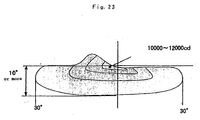
- Cutoff line C1 Light distribution characteristics of a vehicle headlight, in particular low-beam light distribution characteristics, have been standardized as shown in Fig. 23, requiring a horizontal line that reduces glare on oncoming vehicles.
- the difference between light and dark in luminous intensity (hereinafter referred to as "cutoff line C1") is formed at a 15-degree elbow line and provides better recognition of pedestrians and traffic signs. Additionally, a minimum center luminous intensity of 8000cd or more in the front view provides the driver's far distance visibility.
- center luminous intensities of 20000cd or more for vehicle headlights using a conventional halogen light bulb, and 40000cd or more for vehicle headlights using an HID (xenon discharge lamp) are common.
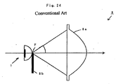
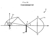
- the vehicle headlight as shown in Fig. 24 or 25 has been hitherto conceived.
- a vehicle headlight 8 is comprised of a light shielding plate 8b that forms a low-beam light distribution pattern, that is, forms the above-mentioned cutoff near the focus F at the back of a convex lens 8a for collecting light.
- the white LED light source 1 is located immediately behind the light shielding plate 8b.
- Light emitted from the white LED light source 1 travels toward the focus F of the convex lens 8a and is collected by the convex lens 8a, with unnecessary or unwanted light blocked by the light shielding plate 8b which is provided near the focus F, thus causing the light to be irradiated forward in a light distribution pattern having a so-called low-beam cutoff as shown in Fig. 23.
- a vehicle headlight 9 is comprised of a light shielding plate 9b that forms a low-beam light distribution pattern, that is, it forms the above-mentioned cutoff near the focus F at the back of convex lens 9a.
- a reflector 9c includes or consists of a rotary elliptic surface that has a focus located near the focus F of the convex lens 9a and has another focus located on the optical axis of the convex lens 9a.
- the white LED light source 1 can be located near the other focus of the reflector 9c and the shielding plate 9b can be arranged perpendicularly to the optical axis of the convex lens 9a, that is, in a horizontal orientation relative to the convex lens 9a.
- Light emitted from the white LED light source 1 is reflected by the reflector 9c, travels toward one of the focuses, e.g. , the focus F of the convex lens 9a, and is collected by the convex lens 9a.
- Unnecessary or unwanted light can be partially or totally blocked by the light shielding plate 9b provided near the focus F, thus causing the light to be irradiated forward in a light distribution pattern having a so-called low-beam cutoff as shown in Fig. 23.
- the emission shape of the white LED light source 1 is rectangular or circular, making it difficult to form a clear cutoff without using the light shielding plate 8b or 9b.
- a luminous intensity value of a light-collecting optical system is, in general, roughly determined by light source brightness (brightness at the focus position of the secondary optical system's lens) and secondary optical system area. Therefore, it is difficult for LED light sources that are less bright than the existing halogen light bulbs or HIBs to achieve a peak luminous intensity value.
- the luminous intensity value near the focus F declines sharply with increasing distance of the light shielding plate 8b from the emission portion of the LED light source 1.
- the light shielding plate 8b be located within 2mm from the emission portion to obtain approximately 60% of luminous intensity as shown by the graph in Fig. 26, it is difficult and nearly impossible to arrange the light shielding plate 8b within 2mm from the emission portion because the LED light source 1 is commonly covered with the resin-molded lens 5 for improved light extraction efficiency and protection of the LED chip 3, the resin 4 that includes a fluorescent substance, and the gold wires 6a and 7b.
- the emission shape of the emission portion of the LED light source 1 is projected forward by the convex lens 8a, thus reflecting the uneven color and the brightness distribution of the LED chip 3 as is in the light distribution characteristic.
- the emission portion is substantially the surface of the resin 4 that includes the fluorescent substance. Therefore, the color of light on the emission portion surface is determined by the ratio of transmitted light from the LED chip 3 and excitation light generated by the fluorescent substance. Since light transmitted from the LED chip 3 is in abundance directly above the LED chip 3, the light is bluish white in the case of a blue LED chip, with the light turning progressively yellow-tinted white with increasing distance from the chip, thus resulting in uneven color.
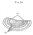
- the emission shape of the white LED light source 1 or an image close thereto is projected forward by the convex lens 8a, thus causing, for example, a secondary cutoff line C2 to be formed as shown in Fig. 27.
- the secondary cutoff line C2 when irradiated onto the screen or road surface, leads to uneven light distribution.
- the focal distances of sets of vehicle headlights 8 can be made different from one another by providing a plurality of sets of vehicle headlights 8 (four sets in the illustration) as shown in Fig. 28.
- This configuration fails to eliminate the secondary cutoff line C2, resulting in a plurality of secondary cutoff lines C2 appearing, and thereby making it difficult or impossible to generate a smooth gradation in the light distribution characteristic.
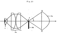
- a second optical system's lens can be arranged to include a second convex lens 8d consisting of a single lens as shown in Fig. 30 and a second convex lens 8e consisting of two lenses as shown in Fig. 31.
- the present invention provides a light source apparatus, such as a vehicle lamp, headlight or auxiliary lamp or headlight, that is particularly suited for irradiating light forward by using a plurality of LED elements.
- a light source that includes a base having a cavity formed on its upper surface; an LED chip mounted in the cavity of the base; a resin portion for sealing the LED chip in the cavity; an optical member disposed above the base and apart from the LED chip; a light shielding portion disposed on the inner surface of the optical member, for forming a cutoff suited for a light distribution pattern for vehicle headlight; and a fluorescent substance layer disposed at least in regions other than the light shielding portion on the inner surface of the optical member.
- the base is preferably formed as a heat radiating core.
- the base is also preferably formed as a ceramic base.
- the optical member is preferably a lens.
- the optical member is also preferably a flat cover.
- the light shielding portion may be positioned within 2mm, preferably 1mm from the LED chip.
- the light shielding portion is preferably comprised of a thin film formed on the inner surface of the optical member.
- the light shielding portion is preferably comprised of a member in plate form adhered to the inner surface of the optical member.
- the member in plate form has a given thickness along the optical axis.
- the light source may further comprise a second light shielding portion disposed on the outer surface of the optical member.
- the inner surface of the light shielding portion is preferably formed as a reflection surface.
- the reflection surface is preferably disposed slanted so as to reflect light from the LED chip.
- the inner surface of the base cavity may include a second reflection surface confronting the reflection surface, for reflecting reflected light from the reflection surface toward the optical axis.
- the reflection surface is preferably comprised of a thin metal film formed on the surface of the light shielding portion.
- the reflection surface is preferably comprised of a surface of the light shielding portion made of, for example, a metallic material.
- the fluorescent substance layer is preferably formed in thin film form.
- the fluorescent substance layer is preferably formed by impregnating silicon film with fluorescent substance.
- the optical member, the inner surface of the light shielding portion or the reflection surface, each of which is in contact with the fluorescent substance layer is preferably coated with a SiO 2 layer.
- the fluorescent substance layer is preferably formed so as to become thinner with increasing distance from the optical axis.
- the outer surface of the flat cover is preferably provided with a microtexture structure at least in regions not corresponding to the light shielding portion.
- the microtexture structure is preferably formed on the flat cover surface.
- the microtexture structure is preferably formed in sheet form separate from the flat cover and adhered to the outer surface of the flat cover. It is preferred that the microtexture structure be formed on a surface not corresponding to the light shielding portion of the flat cover, and that the second light shielding portion be formed projecting along the optical axis on a surface corresponding to the light shielding portion of the flat cover.
- a vehicle headlight comprising any one of the light sources configured for use with a vehicle headlight; and a projection lens disposed such that the focus on the light source side lies in the vicinity of the light shielding portion of the light source apparatus, wherein the projection lens irradiates forward the shape of an emission portion of the light source apparatus cut off by the light shielding portion.
- Light emitted from the LED chip can be emitted from the resin portion directly or after reflection by the cavity internal surface and can fall on the fluorescent substance layer. Then, the fluorescent substance in the fluorescent substance layer is excited by light from the LED chip, producing mixed color light from the mixture of fluorescence by excitation and light from the LED chip.
- the mixed color light can form a cutoff by the light shielding portion and can be emitted along the optical axis. Therefore, the light can be irradiated in a given light distribution pattern for a vehicle headlight by projecting the light with the projection lens along the optical axis, for example, to the front of the automobile.
- Isolation of the LED chip from the fluorescent substance layer allows uneven brightness of the LED chip's emission portion to fall on the fluorescent substance layer in a diffused manner, thus reducing uneven color and forming a gradation with a smooth brightness distribution.
- arrangement of the light shielding portion within the light source apparatus allows the LED chip and the light shielding portion to be brought closer to each other, making it possible to form a cutoff with the high-brightness portion near the emission portion and therefore achieving higher brightness and realizing a clear cutoff.
- the base is formed as a heat radiating core, heat generated due to driving of the LED chip can be radiated via the heat radiating core.
- the heat radiating core can be made, for example, of copper, thus suppressing temperature rise in the LED chip.
- the base is formed as a ceramic base, heat generated due to the driving of the LED chip is radiated via the ceramic base made, for example, of a ceramic material such as aluminum nitride or alumina, thus suppressing temperature rise in the LED chip. Additionally, forming the ceramic base as a laminated structure and providing wiring patterns inside the base eliminate the need for lead materials, etc., for driving the LED chip, reducing the parts count to nearly half and cutting down parts and assembly costs.
- the optical member is a lens
- mixed color light from mixture of fluorescence by excitation and light from the LED chip is converged by the optical member, thus causing the light to be irradiated along the optical axis.
- the optical member is a flat cover
- mixed color light from mixture of fluorescence by excitation and light from the LED chip transmits through the flat cover, thus causing the light to be irradiated as is along the optical axis.
- the light shielding portion is located within 2mm, and more preferably 1mm, from the LED chip, high luminous intensity can be obtained at the light shielding portion. For example, approximately 60% of the LED chip luminous intensity can be obtained when within 2mm and approximately 90% of the LED chip luminous intensity can be obtained when within 1mm.
- the light shielding portion is comprised of a thin film formed on the inner surface of the optical member
- the light shielding portion can be readily constituted, for example, by forming the thin film on the inner surface of the optical member by sputtering, etc., and the configuration of the light source apparatus can be simplified because there is no need to provide members for supporting the light shielding portion.
- the light shielding portion is comprised of a member in plate form adhered to the inner surface of the optical member, the light shielding portion can be readily constituted, for example, by adhering the light shielding portion in plate form to the inner surface of the optical member.
- the configuration of the light source apparatus can be simplified because there is no need to provide members for supporting the light shielding portion.
- the light shielding portion in plate form has a given thickness taken along the optical axis, when light emitted from the light source apparatus along the optical axis is irradiated by the projection lens, color separation can be partly or totally eliminated by shielding light.
- the thickness of the light shielding portion in plate form can be defined by edge portions respectively located near the focus positions of red light and blue light attributed to chromatic aberration of the projection lens.
- the given thickness of the light shielding portion in plate form can correspond to the difference in focal distance between red light and blue light and is approximately 2% of the focal distance of the projection lens.
- a second light shielding portion is provided on the outer surface of the optical member, when light emitted from the light source apparatus along the optical axis is irradiated by the projection lens, color separation can be partly or totally eliminated by shielding light.
- one of the edges of the light shielding portion and the second light shielding portion can be located, respectively, near the focus positions of red light and blue light attributed to aberration of the projection lens.
- the distance between the light shielding portion and the second light shielding portion along the optical axis can correspond to the difference in focal distance between red light and blue light and is approximately 2% of the focal distance of the projection lens.
- the distance can be adjusted by selecting the thickness of the optical member as appropriate.
- the inner surface of the light shielding portion is formed as a reflection surface, light emitted from the LED chip and falling on the light shielding portion is reflected by the reflection surface and returned to the LED chip side. Then, the light is reflected again by the cavity inner surface, and part of the light passes through the optical member and is emitted externally, thus improving light extraction efficiency.
- the reflection surface is arranged in a slanted configuration so as to reflect light from the LED chip, light reflected by the reflection surface travels toward a position displaced from the LED chip, and the light reflected again by the cavity inner surface is guided to regions other than the light shielding portion and is emitted externally, further improving light extraction efficiency.
- a second reflection surface for reflecting reflected light from the reflection surface toward the optical axis is provided opposite the reflection surface and on the inner surface of the base cavity, light reflected by the reflection surfaced travels toward the cavity inner surface and is reflected by the second reflection surface and emitted externally, further improving light extraction efficiency.
- the reflection surface is comprised of a thin metal film formed on the surface of the light shielding portion
- the reflection surface can be readily constituted, for example, by forming the thin metal film on the light shielding portion surface by sputtering.
- the thin metal film can be formed from aluminum, nickel or other similar material.
- the reflection surface is comprised of a member in plate form and is provided on the surface of the light shielding portion
- the reflection surface can be readily constituted, for example, by affixing a metal plate such as stainless steel or aluminum to the surface of the light shielding portion by adhesion or other method.
- the fluorescent substance layer can be maintained roughly at a constant thickness as a whole by forming the layer as a thin film. Therefore, the optical path length is the same for light incident on the fluorescent substance layer at the same incidence angle, thus suppressing uneven color.
- the fluorescent substance layer is formed as a flat convex lens such that the fluorescent substance layer becomes thinner from the inner surface of the optical member to the inside or outside as the distance from the optical axis increases, the optical path length is not substantially extended in the surrounding regions that are distant from the optical axis, despite an increase in incidence angle from the LED chip to the fluorescent substance layer.
- chromaticity deviation e.g. , reduce the possibility of mixed color light from becoming tinged with yellow light.
- the fluorescent substance layer is comprised of a silicon film impregnated with fluorescent substance
- the fluorescent substance layer can be readily formed by impregnating a silicon material with fluorescent substance and forming the fluorescent substance layer on a glass plate, for example, with a spin coater or by molding.
- the coating of the surface with the SiO 2 layer readily brings the fluorescent substance layer into intimate contact with the optical member, regardless of the materials of which the optical member and the light shielding portion are made, thus preventing the fluorescent substance layer from falling off.
- the fluorescent substance layer is formed so as to become thinner with increasing distance from the optical axis, the luminous intensity of light from the LED chip declines with increasing distance from the optical axis.
- the outer surface of the flat cover is provided with a microtexture structure at least in regions not corresponding to the light shielding portion, mixed color light incident on the flat cover inner surface at a relatively large incidence angle can be prevented from becoming attenuated as a result of repeated reflection inside the flat cover.
- the mixed color light can be emitted externally based on the complex surface shape of the microtexture structure, thus improving light extraction efficiency and enhancing brightness on the optical axis through directivity adjustment of light emitted externally by the optical action of the microtexture structure.
- the microtexture structure can be readily provided by providing a shape corresponding to the microtexture in molds during molding of the flat cover.
- the microtexture structure is formed in sheet form separately from the flat cover and adhered to the outer surface of the flat cover, the microtexture structure can be readily provided by adhering the microtexture structure in sheet form to the outer surface of a conventional flat cover.
- the microtexture structure is formed on a surface not corresponding to the light shielding portion of the flat cover and if the second light shielding portion is formed projecting along the optical axis on the surface corresponding to the light shielding portion of the flat cover, effects of chromatic aberration due to the blue light wavelength component can be partially or entirely eliminated by arranging the second light shielding portion (the portion for limiting the blue light wavelength component of light passing through the light shielding portion) outwardly of the microtexture structure.
- Light from the LED chip of the light source apparatus can excite the fluorescent substance in the fluorescent substance layer and then change into mixed color light from mixture with excitation light, which is then emitted via the light shielding portion. Then, light falls on the incidence surface of the projection lens and is converged by the projection lens, thus causing the light to be irradiated forward. At this time, a given light distribution characteristic is formed by the light shielding portion, providing a so-called low-beam light distribution characteristic that partially or entirely eliminates glaring or dazzling light from being projected onto oncoming vehicles.
- heat generated by the LED chip can be partially or entirely prevented from being transferred to the fluorescent substance layer by isolating the fluorescent substance layer from the LED chip. This suppresses temperature rise in the fluorescent substance layer due to heat generation by the LED chip.
- Isolation of the LED chip from the fluorescent substance layer allows uneven brightness of the LED chip's emission portion to fall on the fluorescent substance layer in a diffused manner, thus reducing uneven color and forming a gradation with smooth brightness distribution.
- arrangement of the light shielding portion within the light source apparatus allows the LED chip and the light shielding portion to be brought closer to each other, making it possible to form a cutoff with the high-brightness portion near the emission portion and therefore achieving higher brightness and realizing a clear cutoff.
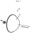
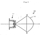
- Figs. 1 to 3 illustrate a configuration of a preferred embodiment of a light source made in accordance with the principles of the present invention.
- the light source is configured as a vehicle headlight 10 that can include a light source apparatus 11 and a projection lens 12 for converging light from the light source apparatus 11.
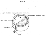
- the light source apparatus 11 can include a base 20, an LED chip 21, a resin portion 22, an optical member 23, a light shielding portion 24, a fluorescent substance layer 25 and a pair of lead terminals 26 and 27, as shown in Figs. 4 and 5.
- the base 20 can be constituted of a highly thermally conductive heat radiating core such as copper and can be provided with a concave cavity 20a formed on the upper surface so as to expand upward.
- the LED chip 21 is, for example, a blue LED chip attached to the bottom surface of the cavity 20a of the base 20 by die bonding, etc., with the electrode portion on the upper surface of the LED chip wire-bonded to the upper end of the lead terminal 26 by a gold wire 26a.
- the upper surface of the base 20 can be similarly wire-bonded to the upper end of the other lead terminal 27 by a gold wire 27a.
- the resin portion 22 is preferably made of a translucent resin such as silicon, that is charged into the cavity 20a of the base 20 and hardened.
- the optical member 23 can be a flat cover (or lens) made of glass, resin or other translucent material and arranged above the LED chip 21 and roughly perpendicularly to the optical axis.
- the light shielding portion 24 can be arranged on part of the region of the inner surface of the optical member 23 (lower surface in Fig. 5), forming a so-called cutoff by blocking part of light emitted from the LED chip 21 and adjusting the light distribution pattern projected by the projection lens 12 into a low-beam light distribution pattern for a vehicle headlight, for example, as shown in Fig. 23.
- the light shielding portion 24 can also be arranged on the optical axis of the LED chip 21 within 2mm, and more preferably 1mm, from the upper surface of the LED chip 21, i.e., the emission surface. Further, the light shielding portion 24 may be provided with a reflection surface 24a on its lower surface and on the side of the LED chip 21.
- the light shielding portion 24 can be made of a metal plate such as stainless steel or aluminum, and the light shielding portion 24 and reflection surface 24a may be adhered or otherwise attached to the inner surface of the optical member 23.
- the reflection surface 24a may be formed as a thin metal film on the surface of the light shielding portion 24, for example, by sputtering.
- Aluminum is preferred, for example, for use as a thin metal film, and can achieve reflectance on the order of 90%.
- the thin metal film may have a two-layer structure of nickel and aluminum. In this case, it is possible to form the flatter reflection surface 24a by arranging nickel on the inside and thereby smoothing the surface of the optical member 23 or the light shielding portion 24. Further, if the light shielding portion 24 and the reflection surface 24a are formed as an integral thin film, a thickness of 100nm or more is preferred to prevent transmission of light.
- the light shielding portion 24 can have a given thickness "d" along the optical axis, as shown in Fig. 6.
- the thickness is preferably the difference between a focus position F1 according to red wavelength light (the longer wavelength side) and a focus position F2 according to blue wavelength light (the shorter wavelength side) of the projection lens 12 (refer to Fig. 7), that is, generally approximately 2% of the focal distance of the projection lens 12 if the projection lens 12 is made of an ordinary material.
- This configuration helps to eliminate chromatic aberration caused by a difference in refraction index of the material of the projection lens 12 for red wavelength light and blue wavelength light, and reliably blocks, using the light shielding portion 24, red wavelength light and blue wavelength light separated due to chromatic aberration of the projection lens, thus reducing or eliminating color separation in light that is irradiated in a forward direction.
- the thickness of the optical member 23 may be associated with the difference in focal distance by providing a second light shielding portion 28 on the outer surface of the optical member 23 and corresponding with the light shielding portion 24 that is positioned on the inner surface of the optical member 23, as shown in Fig. 8.
- the fluorescent substance layer 25 can be formed in thin film form, for example, by impregnating a silicon material with fluorescent substance (not shown) and affixing it to the inner surface of the optical member 23, for example, by adhesion.
- the fluorescent substance is excited by blue light from the LED chip 21 and emits yellow light - excitation light.
- the yellow light is mixed with blue light from the LED chip 21 to change into white light that will be emitted externally.
- the surfaces of the optical member 23 and the light shielding portion 24 can be coated with a SiO 2 film 23a, thus enhancing adhesion of the fluorescent substance layer 25 to the optical member 23 and the light shielding portion 24 and preventing the fluorescent substance layer 25 from falling off.
- the SiO 2 film 23a can be formed by a thin film coating method such as sputtering and may be formed concurrently with the reflection surface 24a if the reflection surface 24a consists of a thin film.
- the SiO 2 film 23a may be omitted.
- the fluorescent substance layer 25 can be arranged at a given distance from the upper surface of the LED chip 21. This reduces thermal conduction from the LED chip 21 to the fluorescent substance layer 25, thus suppressing temperature rise in the fluorescent substance layer 25.
- the conversion efficiency of the fluorescent substance layer 25 generally declines, at 100°C, to approximately 70% of its level at room temperature and to about 50% or less at 150°C. In contrast, the LED chip 21 drops in output to 90% at 100°C and 70% at 150°C.
- chromaticity deviation in mixed color light can be reduced by maintaining the temperature of the fluorescent substance layer 25 low as compared with that of the LED chip 21, for example, at 70% or so of that of the LED chip 21. This can be accomplished through adjustment of thermal resistance between the LED chip 21 and the fluorescent substance layer 25 and by adjusting the distance therebetween and the medium provided therebetween, and thereby reducing the difference in efficiency reduction as a result of temperature rise in the LED chip 21 and the fluorescent substance layer 25.
- the light source apparatus 11 shown in Fig. 2 for example, it is possible to reduce the temperature of the fluorescent substance layer 25 to 70°C or so when the temperature of the LED chip 21 is 100°C by spacing the LED chip 21 and the fluorescent substance layer 25 1.2mm apart, thus suppressing the decline in conversion efficiency of the fluorescent substance layer 25 due to temperature rise and reducing chromaticity deviation.
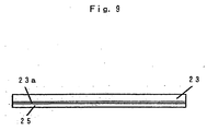
- the fluorescent substance layer 25 can be maintained at a roughly constant thickness as shown in Fig. 9 by forming the fluorescent substance layer 25 as a thin film. Therefore, the optical path length in the fluorescent substance layer 25 is the same for light incident on the fluorescent substance layer 25 at the same incidence angle, thus suppressing uneven color.
- the fluorescent substance layer 25 may be formed in a flat convex lens form so as to become thinner with increasing distance from the optical axis as shown in Figs. 10 or 11.
- the convex side of the fluorescent substance layer 25 can either face inward or away from the optical member 23, and the optical member 23 can be shaped soas to conform to the convex surface of the fluorescent substance layer 25 when the convex surface faces inward toward the optical member 23 as shown in Fig. 11. This ensures that the optical path length is not substantially extended in the surrounding regions distant from the optical axis, despite an increase in incidence angle from the LED chip 21 to the fluorescent substance layer 25, allowing a reduction in chromaticity deviation such as when mixed color light becomes tinged with yellow.
- the fluorescent substance layer 25 can be formed as a thin film, for example, by applying silicon or other material impregnated with a fluorescent substance onto a glass plate, etc. with equipment such as a spin coater, or can be formed by molding. In the case of molding, it is possible to readily produce the fluorescent substance layer 25 with a varying thickness, as mentioned earlier and as exemplified in Figs. 10 or 11.
- the projection lens 12 can include a convex lens and can be arranged such that the optical axis is aligned with the central axis extending roughly horizontally to the front of the base 20 of the light source apparatus 11, and can also be arranged such that the focus position F on the side of the light source apparatus 11 is located near the optical member 23 of the light source apparatus 11.
- a vehicle headlight 10 can be configured as described above, and power supplied to the LED chip 21 causes light to be emitted from the LED chip 21 which causes light to be emitted from the resin portion 22 directly or after reflection by the internal surface of the cavity 20a of the base 20, which in turn causes light to fall on the fluorescent substance layer 25 and excite the fluorescent substance in the fluorescent substance layer 25.
- yellow light - excitation light generated by the fluorescent substance - can be mixed with blue light from the LED chip 21 to change into white light, that will be emitted after transmission through the optical member 23, collected by the projection lens 12 and irradiated in a forward direction.
- part of the white light - the mixed color light - can be blocked by the light shielding portion 24, thus forming a cutoff.
- the image of the cutoff can be projected in the forward direction by the projection lens 12, thus providing a low-beam light distribution pattern L.
- Isolation of the fluorescent substance layer 25 of the light source apparatus 11 from the LED chip 21 suppresses temperature rise in the fluorescent substance layer 25, reducing the difference in efficiency reduction as a result of temperature rise in the LED chip 21 and the fluorescent substance layer 25 and thereby suppressing chromaticity deviation in the mixed color light due to temperature rise.
- the arrangement of the light shielding portion 24 such that it is close to the LED chip 21 in the light source apparatus 11 ensures high luminous intensity on the light shielding portion 24, thus allowing formation of a clear cutoff by projecting the image of the light shielding portion 24 forward by the projection lens 12.
- the vehicle headlight can be simply configured by locating the focus position of the projection lens 12 near the light shielding portion 24 of the light source apparatus 11.
- reflection surface 24a on the inner surface of the light shielding portion 24 results in light incident on the light shielding portion 24 being reflected, allowing, through reuse, more light to pass through the light shielding portion 24 and be irradiated forward. This enhances extraction efficiency of light from the light source apparatus 11 by 10% or so.
- Provision of the light shielding portion 24 with a given thickness can substantially or completely eliminate separation of red tight from blue light due to chromatic aberration of the projection lens 12, thus changing light irradiated forward into white light suited for use in the vehicle headlight.
- isolation of the fluorescent substance layer 25 from the LED chip 21 allows light from the LED chip 21 to fall on the fluorescent substance layer 25 in a sufficiently diffused manner, as shown in Fig. 12, thus providing the brightness distribution of the mixed color light from the fluorescent substance layer 25 with a smooth gradation.
- isolation of the fluorescent substance layer 25 from the LED chip 21 may result in a decline in the center brightness to about 2/3, the decline in brightness can be partially compensated for by improved conversion efficiency of the fluorescent substance and improved light extraction efficiency by the reflection surface 24a.
- significant advantages such as reduction in uneven color and reduction in the generation of gradation in the brightness distribution can be obtained.
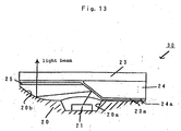
- Fig. 13 illustrates a configuration for major portions of another preferred embodiment of the present invention.
- the light source is configured as a vehicle headlight 30, having roughly the same configuration as the vehicle headlight 10, but differing from the vehicle headlight 10 shown in Figs. 1 and 2 in that the reflection surface 24a of the light source apparatus 11 has a portion that is arranged diagonally relative to the surface that is perpendicular to the optical axis and in that the inner surface of the cavity 20a of the base 20 has a portion that is correspondingly formed as an oddly shaped reflection horn 20b.
- the reflection surface 24a is formed by three-dimensionally configuring the light shielding portion 24, formed with a light shielding material, along the optical axis and mirror-polishing the surface of the light shielding portion 24.
- the vehicle headlight 30 can function in a similar manner as compared to the vehicle headlight 10 shown in Figs. 1 and 2, and the majority of light incident on the light shielding portion 24 can be reflected by the reflection surface 24a, guided to the oddly shaped reflection horn 20b of the cavity 20a of the base 20, reflected by the oddly shaped reflection horn 20b and can fall onto the fluorescent substance layer 25 as secondary reflected light.
- Mixed color light from mixture with resultant excitation light can be emitted externally via the optical member 23. This further improves extraction efficiency of light from the light source apparatus 11.
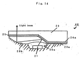
- Fig. 14 illustrates another preferred embodiment of the invention in which the light source is configured as a vehicle headlight 40.
- Vehicle headlight 40 is an example of a modification of the vehicle headlight 30 shown in Fig. 13, and differs from the vehicle headlight 30 in that the reflection surface 24a of the light source apparatus 1 can include a thin metal film that also functions as the light shielding portion 24, and in that the optical member 23 can be correspondingly formed three-dimensionally so as to constitute the surface of the reflection surface 24a.
- the vehicle headlight 40 can function in a similar manner as the vehicle headlight 30 shown in Fig. 13, and the majority of light incident on the reflection surface 24a can be reflected, guided to the oddly shaped reflection horn 20b of the cavity 20a of the base 20, reflected by the oddly shaped reflection horn 20b, and can fall onto the fluorescent substance layer 25 as secondary reflected light. As a result, mixed color light from mixture with resultant excitation light is emitted externally via the optical member 23. This further improves extraction efficiency of light from the light source apparatus 11.
- Fig. 15 illustrates another preferred embodiment of the invention in which the light source is configured as a vehicle headlight 50.
- the vehicle headlight 50 can have roughly the same configuration as the vehicle headlight 10, but differs from the vehicle headlight 10 shown in Figs. 1 and 2 in that the light source apparatus 11 can be provided with a base 51 configured as a ceramic base in place of the base 20 and in that the outer surface of the optical member 23 is provided with a microlens array 52 as a microtexture structure.
- the base 51 can, for example, be made of a ceramic material such as aluminum nitride or alumina to form a ceramic base of laminated structure.
- the base 51 can include wiring patterns 51b and 51c for the LED chip 21.
- the microlens array 52 in the illustration can be formed integrally as a separate body and can be affixed to the optical member 23, that is the flat cover, for example, by adhesion.
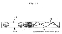
- the microlens array 52 can emit light (light that is incident on the optical member 23 at a relatively large angle, repeatedly reflected by the inner surface within the optical member 23 and no longer capable of being emitted from the optical member 23 as shown in Fig. 16) from the outer surface of the optical member 23 as shown in Fig. 17.
- microlens array 52 can be employed as a microtexture structure in this case, the present invention is not limited thereby and other structures such as a microprism array 53 shown in Fig. 18 or a microprism array 54 shown in Fig. 19 may be provided as long as the microprism arrays 53 or 54 or other structure have similar optical functionality.
- microlenses of the microlens array 52 are formed as non-spherical lenses or by forming individual microprisms of the microprism array 53 or 54 as prisms in pyramid form, it is possible to refract light emitted from the optical member 23 using individual microlenses or microprisms and impart directivity along the optical axis to the emitted light.
- the vehicle headlight 50 functions similar to the vehicle headlight 10 shown in Figs. 1 and 2, and it is possible to cause more light to be diffused forward, as shown by a solid line in Fig. 20, by externally radiating light that is repeatedly reflected by the inner surface within the optical member 23 serving as the flat cover, using the microlens array 52, thus improving extraction efficiency of light from the light source apparatus 11 by about 5 to 20%.
- microlenses of the microlens array 52 are formed as semispherical lenses of 50 ⁇ m in diameter.
- the wiring patterns 51b and 51c can be integrated into the base 51 and provided in place of the lead terminals 27 that are separate from the base, thus keeping the parts count low and reducing parts and assembly costs.
- a second light shielding portion 28 is provided on the outer surface of the optical member 23 in the vehicle headlight 50 to bring the substantial thickness of the light shielding portion 24 to the given thickness d and thereby compensate for chromatic aberration of the projection lens 12, it is necessary to arrange the end edge of the second light shielding portion 28 forward or outward of the microlens array 52.
- the plate shaped member that can form the second light shielding portion 28 may be arranged at a position on the outer surface of the optical member 23 corresponding to the light shielding portion 24, as shown in Fig. 21.
- a structure that is substantially equivalent to the plate shaped member may be formed in advance and be integrally formed with the optical member 23 and coated or painted with light shielding material.
- the end edges of the light shielding portion 24 and the second light shielding portion 28 are formed so as to eliminate light that is glaring to oncoming vehicles on the right-hand forward side of the automobile, with low-beam light distribution limited to traffic on left-hand side, the present invention is not limited thereby and a similar effect can be obtained, in the case of traffic on right-hand side, by reversing the horizontal arrangement of the end edges of the light shielding portions 24 and 28.
- the cavity of the base structure in which the LED chip is located can be integrally formed in the top surface of the base structure or it can be independently formed and attached to the top of the base structure.
- the cavity can be formed as a part of the LED chip itself such that the LED chip radiates light along the optical axis of the light source device.
- the light source can be used in apparatus other than vehicle headlights, such as vehicle tail lights, projection lights, light boards, and any type of lighting device in which directivity of light is desired and the light source is compact.
Landscapes
- Engineering & Computer Science (AREA)
- General Engineering & Computer Science (AREA)
- Physics & Mathematics (AREA)
- Optics & Photonics (AREA)
- Microelectronics & Electronic Packaging (AREA)
- Non-Portable Lighting Devices Or Systems Thereof (AREA)
- Arrangement Of Elements, Cooling, Sealing, Or The Like Of Lighting Devices (AREA)
- Led Device Packages (AREA)
Applications Claiming Priority (2)
| Application Number | Priority Date | Filing Date | Title |
|---|---|---|---|
| JP2003323820A JP4140042B2 (ja) | 2003-09-17 | 2003-09-17 | 蛍光体を用いたled光源装置及びled光源装置を用いた車両前照灯 |
| JP2003323820 | 2003-09-17 |
Publications (2)
| Publication Number | Publication Date |
|---|---|
| EP1526580A2 true EP1526580A2 (fr) | 2005-04-27 |
| EP1526580A3 EP1526580A3 (fr) | 2006-03-08 |
Family
ID=34270039
Family Applications (1)
| Application Number | Title | Priority Date | Filing Date |
|---|---|---|---|
| EP04008913A Withdrawn EP1526580A3 (fr) | 2003-09-17 | 2004-04-14 | Source lumineuse pour lampe de vehicule |
Country Status (4)
| Country | Link |
|---|---|
| US (2) | US7246930B2 (fr) |
| EP (1) | EP1526580A3 (fr) |
| JP (1) | JP4140042B2 (fr) |
| CN (1) | CN100570205C (fr) |
Cited By (2)
| Publication number | Priority date | Publication date | Assignee | Title |
|---|---|---|---|---|
| WO2007090365A1 (fr) * | 2006-02-06 | 2007-08-16 | Osram Opto Semiconductors Gmbh | Boitier pour un composant a diodes electroluminescentes et composant a diodes electroluminescentes |
| US8410500B2 (en) | 2006-12-21 | 2013-04-02 | Koninklijke Philips Electronics N.V. | Light-emitting apparatus with shaped wavelength converter |
Families Citing this family (88)
| Publication number | Priority date | Publication date | Assignee | Title |
|---|---|---|---|---|
| JP4140042B2 (ja) * | 2003-09-17 | 2008-08-27 | スタンレー電気株式会社 | 蛍光体を用いたled光源装置及びled光源装置を用いた車両前照灯 |
| JP4402425B2 (ja) * | 2003-10-24 | 2010-01-20 | スタンレー電気株式会社 | 車両前照灯 |
| US9070850B2 (en) | 2007-10-31 | 2015-06-30 | Cree, Inc. | Light emitting diode package and method for fabricating same |
| US7821023B2 (en) * | 2005-01-10 | 2010-10-26 | Cree, Inc. | Solid state lighting component |
| CN100532922C (zh) * | 2005-10-27 | 2009-08-26 | 财团法人车辆研究测试中心 | 供led头灯组用的小型化led照明模组 |
| KR100788669B1 (ko) * | 2005-11-02 | 2007-12-26 | 삼성전자주식회사 | 발광 디바이스 및 이를 광원으로 사용하는 백라이트 유닛및 이를 적용한 영역별 순차 구동방식 액정표시장치 |
| EP1954978B1 (fr) * | 2005-11-17 | 2015-10-28 | Philips Intellectual Property & Standards GmbH | Dispositif d' eclairage et procede de guidage de lumiere |
| CN101326400B (zh) * | 2005-12-12 | 2011-02-23 | 皇家飞利浦电子股份有限公司 | 用于具有低光束功能的车辆前灯的发光二极管准直仪元件 |
| EP1969633B1 (fr) * | 2005-12-22 | 2018-08-29 | Cree, Inc. | Dispositif d' eclairage |
| JP4587048B2 (ja) * | 2006-04-17 | 2010-11-24 | スタンレー電気株式会社 | 車両用灯具 |
| US7661840B1 (en) | 2006-06-21 | 2010-02-16 | Ilight Technologies, Inc. | Lighting device with illuminated front panel |
| US20080029720A1 (en) | 2006-08-03 | 2008-02-07 | Intematix Corporation | LED lighting arrangement including light emitting phosphor |
| JP4783718B2 (ja) * | 2006-11-27 | 2011-09-28 | 新光電気工業株式会社 | 照明装置 |
| US7686478B1 (en) | 2007-01-12 | 2010-03-30 | Ilight Technologies, Inc. | Bulb for light-emitting diode with color-converting insert |
| US8109656B1 (en) | 2007-01-12 | 2012-02-07 | Ilight Technologies, Inc. | Bulb for light-emitting diode with modified inner cavity |
| US20080198572A1 (en) | 2007-02-21 | 2008-08-21 | Medendorp Nicholas W | LED lighting systems including luminescent layers on remote reflectors |
| US8092042B2 (en) * | 2007-05-03 | 2012-01-10 | Ruud Lighting, Inc. | Shield member in LED apparatus |
| US7663315B1 (en) | 2007-07-24 | 2010-02-16 | Ilight Technologies, Inc. | Spherical bulb for light-emitting diode with spherical inner cavity |
| TW200915597A (en) * | 2007-09-17 | 2009-04-01 | Everlight Electronics Co Ltd | Light emitting diode device |
| EP2068068B1 (fr) * | 2007-12-07 | 2013-11-20 | Stanley Electric Co., Ltd. | Phare de véhicule |
| RU2525834C2 (ru) * | 2008-01-22 | 2014-08-20 | Конинклейке Филипс Электроникс Н.В. | Осветительное устройство с сид и передающим основанием, включающим люминесцентный материал |
| US10008637B2 (en) | 2011-12-06 | 2018-06-26 | Cree, Inc. | Light emitter devices and methods with reduced dimensions and improved light output |
| JP5216362B2 (ja) * | 2008-02-20 | 2013-06-19 | スタンレー電気株式会社 | Led光源ユニット |
| US7932529B2 (en) * | 2008-08-28 | 2011-04-26 | Visera Technologies Company Limited | Light-emitting diode device and method for fabricating the same |
| US8342720B2 (en) * | 2008-10-10 | 2013-01-01 | Stanley Electric Co., Ltd. | Vehicle light and road illumination device |
| JP5227135B2 (ja) * | 2008-10-10 | 2013-07-03 | スタンレー電気株式会社 | 半導体発光装置およびその製造方法 |
| JP5582380B2 (ja) | 2009-03-24 | 2014-09-03 | スタンレー電気株式会社 | 車両用灯具 |
| US7807484B2 (en) * | 2008-10-15 | 2010-10-05 | Visera Technologies Company Limited | Light-emitting diode device and method for fabricating the same |
| JP5781935B2 (ja) * | 2008-11-21 | 2015-09-24 | コーニンクレッカ フィリップス エヌ ヴェ | 出力照明を生成する照明装置及び方法 |
| US7828453B2 (en) | 2009-03-10 | 2010-11-09 | Nepes Led Corporation | Light emitting device and lamp-cover structure containing luminescent material |
| US7972023B2 (en) * | 2009-03-10 | 2011-07-05 | Nepes Led Corporation | Lamp-cover structure containing luminescent material |
| US8337030B2 (en) | 2009-05-13 | 2012-12-25 | Cree, Inc. | Solid state lighting devices having remote luminescent material-containing element, and lighting methods |
| US20110051413A1 (en) * | 2009-08-25 | 2011-03-03 | Abl Ip Holding Llc | Optic shielding |
| WO2011037877A1 (fr) | 2009-09-25 | 2011-03-31 | Cree, Inc. | Dispositif d'éclairage à faible éblouissement et à grande uniformité du niveau de lumière |
| US8466611B2 (en) | 2009-12-14 | 2013-06-18 | Cree, Inc. | Lighting device with shaped remote phosphor |
| JP5518533B2 (ja) * | 2010-03-12 | 2014-06-11 | 株式会社小糸製作所 | 車両用前照灯および車両用前照灯用の発光モジュール |
| TWM390398U (en) * | 2010-04-16 | 2010-10-11 | Depo Auto Parts Industrial Co Ltd | Headlamp |
| JP5538089B2 (ja) * | 2010-06-23 | 2014-07-02 | スタンレー電気株式会社 | 車両用灯具ユニット |
| US8604678B2 (en) | 2010-10-05 | 2013-12-10 | Intematix Corporation | Wavelength conversion component with a diffusing layer |
| US8957585B2 (en) | 2010-10-05 | 2015-02-17 | Intermatix Corporation | Solid-state light emitting devices with photoluminescence wavelength conversion |
| US8610341B2 (en) | 2010-10-05 | 2013-12-17 | Intematix Corporation | Wavelength conversion component |
| US9546765B2 (en) | 2010-10-05 | 2017-01-17 | Intematix Corporation | Diffuser component having scattering particles |
| US8614539B2 (en) | 2010-10-05 | 2013-12-24 | Intematix Corporation | Wavelength conversion component with scattering particles |
| KR20130139938A (ko) | 2010-10-05 | 2013-12-23 | 인터매틱스 코포레이션 | 포토루미네센스 파장 변환을 구비한 고체상태 발광 디바이스 및 표지판 |
| JP2012099282A (ja) * | 2010-10-29 | 2012-05-24 | Sharp Corp | 照明装置及び車両用前照灯 |
| US9648673B2 (en) | 2010-11-05 | 2017-05-09 | Cree, Inc. | Lighting device with spatially segregated primary and secondary emitters |
| JP2012119193A (ja) * | 2010-12-01 | 2012-06-21 | Sharp Corp | 発光装置、車両用前照灯、照明装置、及び車両 |
| JP5702184B2 (ja) * | 2011-02-22 | 2015-04-15 | スタンレー電気株式会社 | 車両用前照灯光学系及び車両用前照灯光学系の製造方法 |
| US10211380B2 (en) | 2011-07-21 | 2019-02-19 | Cree, Inc. | Light emitting devices and components having improved chemical resistance and related methods |
| KR20140038553A (ko) | 2011-07-21 | 2014-03-28 | 크리,인코포레이티드 | 향상된 화학적 내성을 위한 발광 장치 패키지들, 부품들 및 방법들 그리고 관련된 방법들 |
| US10686107B2 (en) | 2011-07-21 | 2020-06-16 | Cree, Inc. | Light emitter devices and components with improved chemical resistance and related methods |
| JP5380498B2 (ja) | 2011-07-25 | 2014-01-08 | シャープ株式会社 | 光源装置、照明装置、車両用前照灯および車両 |
| FR2979595B1 (fr) * | 2011-09-07 | 2016-01-08 | Valeo Vision | Module optique pour projecteur de vehicule automobile |
| DE102011085315A1 (de) * | 2011-10-27 | 2013-05-02 | Automotive Lighting Reutlingen Gmbh | Scheinwerferprojektionsmodul für ein Kraftfahrzeug |
| US9496466B2 (en) | 2011-12-06 | 2016-11-15 | Cree, Inc. | Light emitter devices and methods, utilizing light emitting diodes (LEDs), for improved light extraction |
| US9240530B2 (en) * | 2012-02-13 | 2016-01-19 | Cree, Inc. | Light emitter devices having improved chemical and physical resistance and related methods |
| US9343441B2 (en) | 2012-02-13 | 2016-05-17 | Cree, Inc. | Light emitter devices having improved light output and related methods |
| AT512589B1 (de) * | 2012-03-12 | 2014-06-15 | Zizala Lichtsysteme Gmbh | Lichtleitelement für einen Laser-Fahrzeugscheinwerfer sowie Fahrzeugscheinwerfer |
| JP5912712B2 (ja) * | 2012-03-21 | 2016-04-27 | スタンレー電気株式会社 | 照明用光学系 |
| DE102012212244A1 (de) * | 2012-07-12 | 2014-01-16 | Osram Gmbh | Fahrzeug-Leuchtvorrichtung mit Halbleiterlichtquelle |
| JP5885347B2 (ja) * | 2012-07-26 | 2016-03-15 | アルプス電気株式会社 | セグメント表示装置 |
| CN102911668A (zh) * | 2012-10-15 | 2013-02-06 | 深圳市聚飞光电股份有限公司 | 混合荧光粉、荧光胶、琥珀色led及车灯 |
| DE102012221908A1 (de) * | 2012-11-29 | 2014-06-05 | Osram Gmbh | Leuchtmodul für eine Fahrzeug-Leuchtvorrichtung mit Halbleiterlichtquelle |
| CN103851546B (zh) * | 2012-11-30 | 2017-07-14 | 深圳市海洋王照明工程有限公司 | 光源结构及含有该光源结构的跑道警戒灯 |
| US20140185269A1 (en) | 2012-12-28 | 2014-07-03 | Intermatix Corporation | Solid-state lamps utilizing photoluminescence wavelength conversion components |
| JP6062249B2 (ja) * | 2013-01-09 | 2017-01-18 | 日立マクセル株式会社 | 車両用灯具 |
| AT513916B1 (de) * | 2013-02-07 | 2015-04-15 | Zizala Lichtsysteme Gmbh | Scheinwerfer für ein Kraftfahrzeug und Verfahren zum Erzeugen einer Lichtverteilung |
| WO2014151263A1 (fr) | 2013-03-15 | 2014-09-25 | Intematix Corporation | Composants de conversion de longueur d'onde à photoluminescence |
| US20140334132A1 (en) * | 2013-05-13 | 2014-11-13 | River Point, Llc | Medical Headlamp Optics |
| CN103939821B (zh) * | 2014-04-17 | 2017-03-29 | 南宁燎旺车灯有限责任公司 | 一种反射式led汽车前照灯 |
| WO2016146161A1 (fr) * | 2015-03-16 | 2016-09-22 | Osram Opto Semiconductors Gmbh | Appareil de fourniture de faisceau lumineux |
| AT517409B1 (de) * | 2015-06-30 | 2017-06-15 | Zkw Group Gmbh | Leuchtmodul für einen Fahrzeugscheinwerfer sowie Fahrzeugscheinwerfer |
| CN104990020A (zh) * | 2015-08-04 | 2015-10-21 | 苏州晶品新材料股份有限公司 | 一种双面出光薄片式led汽车大灯 |
| KR102580682B1 (ko) * | 2015-12-02 | 2023-09-21 | 엘지이노텍 주식회사 | 조명장치 및 이를 포함하는 차량용 램프 |
| KR102462648B1 (ko) * | 2016-01-08 | 2022-11-04 | 쑤저우 레킨 세미컨덕터 컴퍼니 리미티드 | 발광소자 패키지 |
| EP3228926B1 (fr) * | 2016-03-29 | 2021-07-07 | LG Electronics Inc. | Dispositif d'éclairage pour véhicule |
| KR101704616B1 (ko) * | 2016-07-08 | 2017-02-08 | 은현수 | 헤드라이트용 플라스틱 복합렌즈 |
| TWI699496B (zh) * | 2017-03-31 | 2020-07-21 | 億光電子工業股份有限公司 | 發光裝置和照明模組 |
| USD839138S1 (en) * | 2017-07-24 | 2019-01-29 | Indive Ltd. | Direction indicator |
| DE102017117027B3 (de) * | 2017-07-27 | 2018-12-13 | SMR Patents S.à.r.l. | Projektionsvorrichtung, Rückblickvorrichtung und Kraftfahrzeug |
| TWI695521B (zh) | 2017-08-04 | 2020-06-01 | 億光電子工業股份有限公司 | Led封裝結構及其製造方法 |
| KR102006188B1 (ko) * | 2017-12-29 | 2019-08-01 | 엘지전자 주식회사 | 반도체 발광 소자를 이용한 차량용 램프 및 그 제어방법 |
| CN116677952A (zh) * | 2018-12-25 | 2023-09-01 | 株式会社小糸制作所 | 光学单元 |
| JP7385444B2 (ja) * | 2019-11-25 | 2023-11-22 | 株式会社小糸製作所 | 光源ユニット、及びそれを備えた車両用灯具 |
| CN114709318B (zh) * | 2022-03-31 | 2025-06-03 | Tcl华星光电技术有限公司 | 一种led封装结构及显示面板 |
| JP7753957B2 (ja) * | 2022-03-31 | 2025-10-15 | 市光工業株式会社 | 車両用前照灯 |
| US12123561B2 (en) | 2022-12-12 | 2024-10-22 | Valeo North America, Inc. | Multi-color illuminated component with a single-color light source |
| JP2026006326A (ja) * | 2024-06-28 | 2026-01-16 | 市光工業株式会社 | 車両用灯具及び車両用灯具用の基板 |
Family Cites Families (66)
| Publication number | Priority date | Publication date | Assignee | Title |
|---|---|---|---|---|
| JPS5114439B2 (fr) * | 1972-05-15 | 1976-05-10 | ||
| JPS59124179A (ja) | 1982-12-29 | 1984-07-18 | Fujitsu Ltd | 発光ダイオ−ド装置 |
| JPH01120702A (ja) | 1987-11-05 | 1989-05-12 | Koito Mfg Co Ltd | 車輌用前照灯 |
| JPH05226691A (ja) | 1992-01-20 | 1993-09-03 | Nec Corp | 光半導体装置 |
| JP2740931B2 (ja) | 1992-12-29 | 1998-04-15 | 京セラ株式会社 | 画像形成装置 |
| JP3207036B2 (ja) * | 1994-02-15 | 2001-09-10 | 株式会社小糸製作所 | 発光素子を使った灯具の光学設計方法 |
| DE19638667C2 (de) * | 1996-09-20 | 2001-05-17 | Osram Opto Semiconductors Gmbh | Mischfarbiges Licht abstrahlendes Halbleiterbauelement mit Lumineszenzkonversionselement |
| DE29724847U1 (de) * | 1996-06-26 | 2004-09-30 | Osram Opto Semiconductors Gmbh | Lichtabstrahlendes Halbleiterbauelement mit Lumineszenzkonversionselement |
| US6613247B1 (en) * | 1996-09-20 | 2003-09-02 | Osram Opto Semiconductors Gmbh | Wavelength-converting casting composition and white light-emitting semiconductor component |
| JP3065263B2 (ja) | 1996-12-27 | 2000-07-17 | 日亜化学工業株式会社 | 発光装置及びそれを用いたled表示器 |
| JP3774021B2 (ja) | 1997-03-12 | 2006-05-10 | オムロン株式会社 | 車両分離器 |
| US6441943B1 (en) * | 1997-04-02 | 2002-08-27 | Gentex Corporation | Indicators and illuminators using a semiconductor radiation emitter package |
| JPH1187782A (ja) | 1997-09-03 | 1999-03-30 | Oki Electric Ind Co Ltd | 発光ダイオード |
| US6204523B1 (en) | 1998-11-06 | 2001-03-20 | Lumileds Lighting, U.S., Llc | High stability optical encapsulation and packaging for light-emitting diodes in the green, blue, and near UV range |
| WO2001008452A1 (fr) * | 1999-07-23 | 2001-02-01 | Patent-Treuhand-Gesellschaft für elektrische Glühlampen mbH | Substance fluorescente pour sources lumineuses et source lumineuse correspondante |
| US6504301B1 (en) | 1999-09-03 | 2003-01-07 | Lumileds Lighting, U.S., Llc | Non-incandescent lightbulb package using light emitting diodes |
| JP2001127346A (ja) | 1999-10-22 | 2001-05-11 | Stanley Electric Co Ltd | 発光ダイオード |
| JP2001196639A (ja) | 2000-01-12 | 2001-07-19 | Sanyo Electric Co Ltd | Led発光素子及びその製造方法 |
| JP2001210872A (ja) | 2000-01-26 | 2001-08-03 | Sanyo Electric Co Ltd | 半導体発光装置及びその製造方法 |
| DE10009782B4 (de) * | 2000-03-01 | 2010-08-12 | Automotive Lighting Reutlingen Gmbh | Beleuchtungseinrichtung eines Fahrzeugs |
| DE10027018B4 (de) | 2000-05-31 | 2010-09-09 | Robert Bosch Gmbh | Fahrzeugscheinwerfer nach dem Projektionsprinzip und Beleuchtungseinrichtung eines Fahrzeugs mit wenigstens einem solchen Scheinwerfer |
| JP2001345483A (ja) | 2000-05-31 | 2001-12-14 | Toshiba Lighting & Technology Corp | 発光ダイオード |
| JP2002094127A (ja) | 2000-09-20 | 2002-03-29 | Sunx Ltd | 投光素子及び反射型光電センサ |
| US7078151B2 (en) * | 2000-09-20 | 2006-07-18 | Hitachi Chemical Co., Ltd. | Photosensitive element, method for forming resist pattern, and method for manufacturing printed wiring board |
| US6639360B2 (en) * | 2001-01-31 | 2003-10-28 | Gentex Corporation | High power radiation emitter device and heat dissipating package for electronic components |
| JP3942371B2 (ja) | 2001-03-26 | 2007-07-11 | 三洋電機株式会社 | 白色表示器 |
| JP4789350B2 (ja) * | 2001-06-11 | 2011-10-12 | シチズン電子株式会社 | 発光ダイオードの製造方法 |
| FR2826098B1 (fr) * | 2001-06-14 | 2003-12-26 | Valeo Vision | Dispositif d'eclairage ou de signalisation, notamment pour vehicule, comportant plusieurs sources lumineuses |
| JP4665205B2 (ja) | 2001-07-16 | 2011-04-06 | スタンレー電気株式会社 | 灯具用線状光源 |
| JP4431932B2 (ja) | 2001-07-16 | 2010-03-17 | スタンレー電気株式会社 | 灯具 |
| JP3948650B2 (ja) * | 2001-10-09 | 2007-07-25 | アバゴ・テクノロジーズ・イーシービーユー・アイピー(シンガポール)プライベート・リミテッド | 発光ダイオード及びその製造方法 |
| JP4089866B2 (ja) | 2001-10-12 | 2008-05-28 | スタンレー電気株式会社 | 投光ユニットおよび該投光ユニットを具備するled車両用照明灯具 |
| JP2003123520A (ja) * | 2001-10-18 | 2003-04-25 | Koito Mfg Co Ltd | 赤外光照射ランプ兼用投射型前照灯 |
| DE10205779B4 (de) | 2002-02-13 | 2010-04-15 | Bayerische Motoren Werke Aktiengesellschaft | Scheinwerfer |
| ITTO20020142A1 (it) | 2002-02-19 | 2003-08-19 | Fraen Corp Srl | Unita' integrata di proiezione, in particolare per la proiezione di immagini e-o di fasci luminosi a geometria prestabilita. |
| US6943379B2 (en) * | 2002-04-04 | 2005-09-13 | Toyoda Gosei Co., Ltd. | Light emitting diode |
| JP4080780B2 (ja) * | 2002-04-23 | 2008-04-23 | 株式会社小糸製作所 | 光源ユニット |
| FR2839139B1 (fr) * | 2002-04-25 | 2005-01-14 | Valeo Vision | Module d'eclairage elliptique sans cache realisant un faisceau d'eclairage a coupure et projecteur comportant un tel module |
| DE20206833U1 (de) | 2002-04-30 | 2002-07-18 | Automotive Lighting Reutlingen GmbH, 72762 Reutlingen | Nebel- oder Abblendlichtscheinwerfer |
| JP3707688B2 (ja) * | 2002-05-31 | 2005-10-19 | スタンレー電気株式会社 | 発光装置およびその製造方法 |
| JP4360481B2 (ja) * | 2002-07-10 | 2009-11-11 | 株式会社小糸製作所 | 車両用灯具 |
| JP2004047748A (ja) * | 2002-07-12 | 2004-02-12 | Stanley Electric Co Ltd | 発光ダイオード |
| JP2004063499A (ja) | 2002-07-24 | 2004-02-26 | Ichikoh Ind Ltd | Ledを光源とする車両用灯具 |
| JP4002159B2 (ja) * | 2002-09-03 | 2007-10-31 | 株式会社小糸製作所 | 車両用前照灯 |
| JP4024628B2 (ja) * | 2002-09-03 | 2007-12-19 | 株式会社小糸製作所 | 車両用前照灯 |
| JP4083516B2 (ja) * | 2002-09-03 | 2008-04-30 | 株式会社小糸製作所 | 車両用前照灯 |
| JP4143732B2 (ja) * | 2002-10-16 | 2008-09-03 | スタンレー電気株式会社 | 車載用波長変換素子 |
| JP4294295B2 (ja) * | 2002-11-06 | 2009-07-08 | 株式会社小糸製作所 | 車両用前照灯 |
| JP4071089B2 (ja) | 2002-11-06 | 2008-04-02 | 株式会社小糸製作所 | 車両用前照灯 |
| JP4040955B2 (ja) * | 2002-11-06 | 2008-01-30 | 株式会社小糸製作所 | 車両用前照灯及びその製造方法 |
| FR2849158B1 (fr) * | 2002-12-20 | 2005-12-09 | Valeo Vision | Module d'eclairage pour projecteur de vehicule |
| JP4047186B2 (ja) * | 2003-02-10 | 2008-02-13 | 株式会社小糸製作所 | 車両用前照灯及び光学ユニット |
| JP4083593B2 (ja) * | 2003-02-13 | 2008-04-30 | 株式会社小糸製作所 | 車両用前照灯 |
| JP4369668B2 (ja) * | 2003-02-13 | 2009-11-25 | 株式会社小糸製作所 | 車両用前照灯 |
| JP4018016B2 (ja) | 2003-03-31 | 2007-12-05 | 株式会社小糸製作所 | 車両用前照灯 |
| JP2004311101A (ja) * | 2003-04-03 | 2004-11-04 | Koito Mfg Co Ltd | 車両用前照灯及び半導体発光素子 |
| JP4102240B2 (ja) | 2003-04-08 | 2008-06-18 | 株式会社小糸製作所 | 車両用前照灯 |
| JP4002207B2 (ja) * | 2003-04-21 | 2007-10-31 | 株式会社小糸製作所 | 車両用前照灯 |
| JP4335621B2 (ja) * | 2003-04-25 | 2009-09-30 | スタンレー電気株式会社 | 車両用灯具 |
| JP4138586B2 (ja) * | 2003-06-13 | 2008-08-27 | スタンレー電気株式会社 | 光源用ledランプおよびこれを用いた車両用前照灯 |
| JP4024721B2 (ja) * | 2003-06-20 | 2007-12-19 | 株式会社小糸製作所 | 車両用灯具及び光源モジュール |
| JP2005044698A (ja) * | 2003-07-24 | 2005-02-17 | Koito Mfg Co Ltd | 車両用灯具及び光源モジュール |
| JP4061251B2 (ja) * | 2003-08-05 | 2008-03-12 | 株式会社小糸製作所 | 車両用灯具 |
| JP4314911B2 (ja) * | 2003-08-20 | 2009-08-19 | スタンレー電気株式会社 | 車両前照灯 |
| EP1515368B1 (fr) * | 2003-09-05 | 2019-12-25 | Nichia Corporation | Équipment d'éclairage |
| JP4140042B2 (ja) * | 2003-09-17 | 2008-08-27 | スタンレー電気株式会社 | 蛍光体を用いたled光源装置及びled光源装置を用いた車両前照灯 |
-
2003
- 2003-09-17 JP JP2003323820A patent/JP4140042B2/ja not_active Expired - Fee Related
-
2004
- 2004-03-25 US US10/808,551 patent/US7246930B2/en not_active Expired - Lifetime
- 2004-04-14 EP EP04008913A patent/EP1526580A3/fr not_active Withdrawn
- 2004-04-30 CN CNB2004100456788A patent/CN100570205C/zh not_active Expired - Fee Related
-
2007
- 2007-07-23 US US11/781,337 patent/US7753573B2/en not_active Expired - Fee Related
Non-Patent Citations (1)
| Title |
|---|
| None * |
Cited By (3)
| Publication number | Priority date | Publication date | Assignee | Title |
|---|---|---|---|---|
| WO2007090365A1 (fr) * | 2006-02-06 | 2007-08-16 | Osram Opto Semiconductors Gmbh | Boitier pour un composant a diodes electroluminescentes et composant a diodes electroluminescentes |
| CN101379626B (zh) * | 2006-02-06 | 2010-06-09 | 奥斯兰姆奥普托半导体有限责任公司 | 用于发光二极管元件的壳体以及发光二极管元件 |
| US8410500B2 (en) | 2006-12-21 | 2013-04-02 | Koninklijke Philips Electronics N.V. | Light-emitting apparatus with shaped wavelength converter |
Also Published As
| Publication number | Publication date |
|---|---|
| US7246930B2 (en) | 2007-07-24 |
| CN100570205C (zh) | 2009-12-16 |
| EP1526580A3 (fr) | 2006-03-08 |
| US20070263403A1 (en) | 2007-11-15 |
| US20050057917A1 (en) | 2005-03-17 |
| JP4140042B2 (ja) | 2008-08-27 |
| US7753573B2 (en) | 2010-07-13 |
| JP2005093191A (ja) | 2005-04-07 |
| CN1598396A (zh) | 2005-03-23 |
Similar Documents
| Publication | Publication Date | Title |
|---|---|---|
| US7246930B2 (en) | Light source and vehicle lamp | |
| JP2005093191A5 (fr) | ||
| EP2511602B1 (fr) | Dispositif électroluminescent | |
| CN100380689C (zh) | 用于车辆使用的波长转换元件 | |
| US8506147B2 (en) | Light source and vehicle lamp | |
| CN103392093B (zh) | 发光模块及车辆用灯具 | |
| JP4665205B2 (ja) | 灯具用線状光源 | |
| JP5266605B2 (ja) | 車両用灯具 | |
| CN100413100C (zh) | 前照灯光源用发光二极管灯 | |
| CN102753883B (zh) | 包括磷光体、辐射源、光学系统和散热器的灯 | |
| US7441928B2 (en) | Lighting device | |
| JP2008305802A (ja) | Led灯具 | |
| CN102563483A (zh) | 发光装置、车辆用前照灯、照明装置及激光元件 | |
| US20110075438A1 (en) | Led light source and vehicle light | |
| US7566152B2 (en) | Vehicular lamp unit | |
| US8376598B2 (en) | Light source unit and vehicular lamp | |
| US8568007B2 (en) | Vehicle headlight | |
| JP2007059864A (ja) | 照明装置および発光ダイオード装置 | |
| CN110906269B (zh) | 一种车灯 | |
| JP4186026B2 (ja) | Led光源装置及びled光源装置を用いた車両前照灯 | |
| JP2008016303A (ja) | 発光装置 | |
| CN112902101B (zh) | 一种远近光一体的车灯 | |
| JP2004288866A (ja) | Ledランプ | |
| JP4239477B2 (ja) | 発光ダイオードおよびledライト | |
| JP2007318176A (ja) | 発光ダイオード |
Legal Events
| Date | Code | Title | Description |
|---|---|---|---|
| PUAI | Public reference made under article 153(3) epc to a published international application that has entered the european phase |
Free format text: ORIGINAL CODE: 0009012 |
|
| AK | Designated contracting states |
Kind code of ref document: A2 Designated state(s): AT BE BG CH CY CZ DE DK EE ES FI FR GB GR HU IE IT LI LU MC NL PL PT RO SE SI SK TR |
|
| AX | Request for extension of the european patent |
Extension state: AL HR LT LV MK |
|
| PUAL | Search report despatched |
Free format text: ORIGINAL CODE: 0009013 |
|
| AK | Designated contracting states |
Kind code of ref document: A3 Designated state(s): AT BE BG CH CY CZ DE DK EE ES FI FR GB GR HU IE IT LI LU MC NL PL PT RO SE SI SK TR |
|
| AX | Request for extension of the european patent |
Extension state: AL HR LT LV MK |
|
| RIC1 | Information provided on ipc code assigned before grant |
Ipc: F21K 7/00 20060101ALI20060118BHEP Ipc: F21S 8/10 20060101ALI20060118BHEP Ipc: F21V 7/00 20060101ALI20060118BHEP Ipc: F21V 5/00 20060101ALI20060118BHEP Ipc: F21V 11/16 20060101ALI20060118BHEP Ipc: H01L 33/00 20060101AFI20050303BHEP |
|
| 17P | Request for examination filed |
Effective date: 20060908 |
|
| AKX | Designation fees paid |
Designated state(s): DE FR GB |
|
| 17Q | First examination report despatched |
Effective date: 20061117 |
|
| STAA | Information on the status of an ep patent application or granted ep patent |
Free format text: STATUS: THE APPLICATION IS DEEMED TO BE WITHDRAWN |
|
| 18D | Application deemed to be withdrawn |
Effective date: 20141101 |