EP1526754A1 - Enceinte de haut-parleur avec circulation d'air à rendement élevé - Google Patents
Enceinte de haut-parleur avec circulation d'air à rendement élevé Download PDFInfo
- Publication number
- EP1526754A1 EP1526754A1 EP03024254A EP03024254A EP1526754A1 EP 1526754 A1 EP1526754 A1 EP 1526754A1 EP 03024254 A EP03024254 A EP 03024254A EP 03024254 A EP03024254 A EP 03024254A EP 1526754 A1 EP1526754 A1 EP 1526754A1
- Authority
- EP
- European Patent Office
- Prior art keywords
- speaker cabinet
- opening
- wavy
- sides
- low
- Prior art date
- Legal status (The legal status is an assumption and is not a legal conclusion. Google has not performed a legal analysis and makes no representation as to the accuracy of the status listed.)
- Granted
Links
Images


Classifications
-
- H—ELECTRICITY
- H04—ELECTRIC COMMUNICATION TECHNIQUE
- H04R—LOUDSPEAKERS, MICROPHONES, GRAMOPHONE PICK-UPS OR LIKE ACOUSTIC ELECTROMECHANICAL TRANSDUCERS; ELECTRIC HEARING AIDS; PUBLIC ADDRESS SYSTEMS
- H04R1/00—Details of transducers, loudspeakers or microphones
- H04R1/20—Arrangements for obtaining desired frequency or directional characteristics
- H04R1/22—Arrangements for obtaining desired frequency or directional characteristics for obtaining desired frequency characteristic only
- H04R1/28—Transducer mountings or enclosures modified by provision of mechanical or acoustic impedances, e.g. resonator, damping means
- H04R1/2807—Enclosures comprising vibrating or resonating arrangements
- H04R1/2815—Enclosures comprising vibrating or resonating arrangements of the bass reflex type
- H04R1/2819—Enclosures comprising vibrating or resonating arrangements of the bass reflex type for loudspeaker transducers
-
- H—ELECTRICITY
- H04—ELECTRIC COMMUNICATION TECHNIQUE
- H04R—LOUDSPEAKERS, MICROPHONES, GRAMOPHONE PICK-UPS OR LIKE ACOUSTIC ELECTROMECHANICAL TRANSDUCERS; ELECTRIC HEARING AIDS; PUBLIC ADDRESS SYSTEMS
- H04R1/00—Details of transducers, loudspeakers or microphones
- H04R1/02—Casings; Cabinets ; Supports therefor; Mountings therein
Definitions
- the present invention relates to speaker construction and more particularly to an improved speaker cabinet with increased air circulation efficiency.
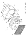
- FIG. 1 A conventional speaker cabinet 10 is illustrated in FIG. 1.
- the speaker cabinet 10 comprises a substantially parallelepiped, hollow case 11 and a cover 12.
- the hollow case 11 comprises a front opening 110, a top 111, a bottom 111, and a rear 112 in which the top 111 and the bottom 111 are obliquely tapered from a pair of opposite edges of the opening 110 to the rear 112.
- Two sides 113 of the hollow case 11 are also extended parallel from another pair of opposite edges of the opening 110 to the rear 112.
- a U-shaped bracket 16 is pivotal about the sides 113 proximate the rear 112. The U-shaped bracket 16 is used to fasten at a predetermined place.
- a sound control circuit 13 is provided on the inner surface of the rear 112 within the hollow case 11.
- the sound control circuit 13 is used to receive audio signals from an amplifier of a sound reproducing device (not shown) and control the same.
- a woofer 120 On the cover 12 there are provided a woofer 120, a tweeter 121, and at least one low-frequency sound reflection channel (one is shown) 122.
- the cover 12 is shaped to snugly fit on the edges of the opening 110.
- audio signals of high and low frequencies generated by the sound control circuit 13 are capable of sending to the woofer 120 and the tweeter 121 respectively.
- the diaphragms of the woofer 120 and the tweeter 121 are thus vibrated to generate low-frequency sounds and high-frequency sounds respectively. Referring to FIG.
- a damping member 14 formed of fabric or foam is provided between the cover 12 and the sound control circuit 13.
- the damping member 14 is used to absorb vibration of low-frequency sounds for avoiding cables 131 and a power cord 132 of the sound control circuit 13 from generating low-frequency resonance. Otherwise, low-frequency sounds may be interfered.
- a grille-like dusk cover 15 is provided on the cover 12 for the protection of the woofer 120 and the tweeter 121 and is used to prevent dust and other tiny, foreign objects from entering into the speaker cabinet 10.
- the top 111 and the bottom 111 of the hollow case 11 are obliquely tapered from a pair of opposite edges of the opening 110 to the rear 112.
- Such design aims at generating an instantaneous vibration on the diaphragm 1201 of the woofer 120 and blowing air inside the hollow case 11 along the oblique inner surfaces of the top 111 and the bottom 111 toward the rear 112 by compressing air inside the case 11 rearward as the diaphragm 1201 moves rearward.
- a 1 V 1 A 2 V 2
- P 1 V 1 P 2 V 2
- a 1 and A 2 are areas of the front containing the opening 110 and the rear 112 of the hollow case 11 respectively
- V 1 and V 2 are flow rates measured at the front containing the opening 110 and the rear 112 of the hollow case 11 respectively when the diaphragm 1201 of the woofer 120 begins to vibrate
- P 1 and P 2 are air pressures measured at the front containing the opening 110 and the rear 112 of the hollow case 11 respectively when the diaphragm 1201 of the woofer 120 begins to vibrate.
- the area A 1 of the front containing the opening 110 is much larger than the area A 2 of the rear 112 since, as stated above, the top 111 and the bottom 111 of the hollow case 11 are obliquely tapered from a pair of opposite edges of the opening 110 to the rear 112.
- the flow rate V 2 at the rear 112 inside the hollow case 11 is much larger than the flow rate V 1 at the opening 110 when the diaphragm 1201 of the woofer 120 vibrates through the application of the above equations.
- air dynamic at the rear 112 inside the hollow case 11 is higher.
- the top 111 and the bottom 111 of the hollow case 11 are obliquely tapered from a pair of opposite edges of the opening 110 to the rear 112. As such, air, flowed from the front to the rear 112 along the oblique inner surfaces of the top 111 and the bottom 111, may flow back toward the opening 110 when it hits the rear 112 due to the compressibility of air.
- At least one low-frequency sounds reflection channel 122 is provided on the cover 12 (or on the rear 112) as best illustrated in the prior speaker cabinet 10 of FIG. 3.
- the provision of the low-frequency sounds reflection channel 122 is adapted to exit the flowed back air toward the outside.
- the prior design suffered a disadvantage.
- the top 111 and the bottom 111 are obliquely tapered from a pair of opposite edges of the opening 110 to the rear 112.
- two sides 113 of the hollow case 11 are extended parallel from another pair of opposite edges of the opening 110 to the rear 112. That is, four sides 111 and 113 are extended to the rear 112.
- most air will flow back from the rear 112 to the cover 12 along the same route only a small portion thereof exits from the low-frequency sounds reflection channel 122.
- the former will cause an adverse vibration of the cover 12, adversely affect the diaphragm 1201 of the woofer 120, and cause distortion in the low-frequency sound.
- the need for improvement with respect to both quality and volume of low-frequency sounds output of the prior speaker cabinet still exists.
- One object of the present invention is to provide a speaker cabinet comprising a hollow case in which a top and a bottom thereof both are wavily tapered from a pair of opposite edges of a front opening to a rear thereof.
- a ratio of an area of the opening to an area of the rear is increased.
- air inside the case will be compressed rearward when a diaphragm of a woofer vibrates.
- the compressed air will quickly flow toward the rear along the wavy, rearward taper inner surfaces of the top and the bottom.
- air dynamic at the rear is higher and stronger low-frequency resonance of the cabinet can be generated.
- air may flow back to the opening when it hits the rear.
- most air will flow back from the rear to at least one low-frequency sounds reflection channel on the cover along the wavy, rearward taper inner surfaces of the top and the bottom prior to exit. This can facilitate air circulation through the case and significantly reduce a probability of secondary reflection of sound wave.
- Another object of the present invention is to provide a speaker cabinet in which two sides of the case are extended parallel from another pair of opposite edges of the opening to the rear. Two arcuate (or inclined) surfaces of the rear proximate the sides are formed integrally with the sides.
- Still another object of the present invention is to provide a speaker cabinet in which by utilizing the wavy, rearward taper shapes of the top and the bottom, air inside the case will be compressed rearward to concentrate on the inner surface of the rear corresponding to the rears of the low-frequency sounds reflection channel when the diaphragm of the woofer vibrates prior to exiting from the low-frequency sounds reflection channel.
- air inside the case will be compressed rearward to concentrate on the inner surface of the rear corresponding to the rears of the low-frequency sounds reflection channel when the diaphragm of the woofer vibrates prior to exiting from the low-frequency sounds reflection channel.
- the vacuum suck effect inside the case outside air will be introduced into the case through the low-frequency sounds reflection channel.
- the speaker cabinet 20 comprises a hollow case 21 and a cover 22.
- the hollow case 21 comprises a front opening 210, a wavy top 211, a wavy bottom 211, and a rear 212 in which the top 211 and the bottom 211 are wavily tapered from a pair of opposite edges of the opening 210 to the rear 212.
- Two sides 213 of the hollow case 21 are also extended parallel from another pair of opposite edges of the opening 210 to the rear 212. In other words, the area of the rear 212 is smaller than that of the opening 210.
- a pivot hole 2130 is provided at either side 213 proximate the rear 212.
- a bracket (not shown) can be provided at the pivot holes 2130 for fastening the hollow case 21 at a predetermined place.
- a sound control circuit 23 is provided on the inner surface of the rear 212 within the hollow case 21. The sound control circuit 23 is used to receive audio signals from an amplifier of a sound reproducing device (not shown) and control the same.
- On the cover 22 there are provided a woofer 220, a tweeter 221, and at least one low-frequency sounds reflection channel (two are shown) 222.
- the cover 22 is shaped to snugly fit on the edges of the opening 210.
- audio signals of high and low frequencies generated by the sound control circuit 23 are capable of sending to the woofer 220 and the tweeter 221 respectively.
- the diaphragms of the woofer 220 and the tweeter 221 are thus vibrated to generate low-frequency sounds and high-frequency sounds respectively.
- a damping member 24 formed of fabric or foam is provided between the cover 22 and the sound control circuit 23 on the inner surface of the rear 212.
- the damping member 24 is used to absorb vibration of low-frequency sounds for avoiding cables 231 and a power cord 232 of the sound control circuit 23 from generating low-frequency resonance. Otherwise, low-frequency sounds may be interfered.
- a grille-like dusk cover 25 is provided on the cover 22 for the protection of the woofer 220 and the tweeter 221 and is used to prevent dust and other tiny, foreign objects from entering into the speaker cabinet 20.
- the wavy top 211 and the wavy bottom 211 of the hollow case 21 are designed to wavily taper from a pair of opposite edges of the opening 210 to the rear 212.
- the top 211 and the bottom 211 are arcuate having two wavy sections in which one wavy section proximate the opening 210 curves inwardly about the hollow case 21 and the other wavy section proximate the rear 212 curves outwardly about the hollow case 21.
- a continuous curve 2110 consisting of the wavy sections is formed.
- a ratio of the area of the opening 210 to the area of the rear 212 is higher than that of the prior speaker cabinet in terms of the same depth of the hollow case 21.
- Air inside the hollow case 21 will be compressed rearward when the diaphragm 2201 of the woofer 220 vibrates (i.e., the diaphragm 2201 moves rearward).
- the compressed air will quickly flow toward the rear 212 along the wavy, rearward taper inner surfaces of the wavy top 211 and the wavy bottom 211.
- air dynamic at the rear 212 is higher and stronger low-frequency resonance of the speaker cabinet 20 can be generated.
- air flowed from the opening 210 to the rear 212 along the wavy, rearward taper inner surfaces of the top 211 and the bottom 211, may flow back toward the opening 210 when it hits the rear 212.
- most air will flow back from the rear 212 to the rears of the low-frequency sounds reflection channels 222 on the cover 22 along a tangent 2111 of the continuous curve 2110 prior to exit because the top 211 and the bottom 211 proximate the rear 212 are curved outwardly toward the hollow case 21.
- each of the top 211 and the bottom 211 may have at least one wavy section in any other embodiment as long as a portion thereof proximate the rear 212 is curved outwardly toward the hollow case 21 for forming a wavy, rearward taper shape without departing from the scope and spirit of the invention.
- This has the advantages of causing the ratio of the area of the opening 210 to the area of the rear 212 to be higher than that of the prior speaker cabinet in terms of the same depth of the hollow case 21.
- two sides 213 of the hollow case 21 are extended parallel from another pair of opposite edges of the opening 210 to the rear 212.
- Two arcuate (or inclined) surfaces 2120 of the rear 212 proximate the sides 213 are formed integrally with the sides 213.
- the surfaces 2120 are curved inwardly toward the hollow case 21, resulting in a rearward taper shape of the rear 212.
- the compressed air is concentrated on the inner surface of the rear 212 corresponding to the low-frequency sounds reflection channels 222. Thereafter, air flowed back from the rear 212 toward the opening 210 will be highly concentrated on the rears of the low-frequency sounds reflection channels 222. As a result, the flowed back air is free to exit from the low-frequency sounds reflection channels 222.
- air circulation through the hollow case 21 is more smooth, probability of secondary reflection of sound wave is significantly reduced, adverse effect on the vibration of the diaphragm 2201 of the woofer 220 caused by the compressed air and vacuum sucking effect inside the hollow case 21 will be substantially eliminated, distortion in the low-frequency sounds is much improved, and both quality and volume of low-frequency sounds output of the woofer are much increased.
Landscapes
- Physics & Mathematics (AREA)
- Engineering & Computer Science (AREA)
- Acoustics & Sound (AREA)
- Signal Processing (AREA)
- Health & Medical Sciences (AREA)
- Otolaryngology (AREA)
- Details Of Audible-Bandwidth Transducers (AREA)
- Obtaining Desirable Characteristics In Audible-Bandwidth Transducers (AREA)
Priority Applications (2)
| Application Number | Priority Date | Filing Date | Title |
|---|---|---|---|
| EP20030024254 EP1526754B1 (fr) | 2003-10-22 | 2003-10-22 | Enceinte de haut-parleur avec circulation d'air à rendement élevé |
| DE2003605187 DE60305187T2 (de) | 2003-10-22 | 2003-10-22 | Lautsprechergehäuse mit erhöhter Effizienz der Luftzirkulation |
Applications Claiming Priority (1)
| Application Number | Priority Date | Filing Date | Title |
|---|---|---|---|
| EP20030024254 EP1526754B1 (fr) | 2003-10-22 | 2003-10-22 | Enceinte de haut-parleur avec circulation d'air à rendement élevé |
Publications (2)
| Publication Number | Publication Date |
|---|---|
| EP1526754A1 true EP1526754A1 (fr) | 2005-04-27 |
| EP1526754B1 EP1526754B1 (fr) | 2006-05-10 |
Family
ID=34384603
Family Applications (1)
| Application Number | Title | Priority Date | Filing Date |
|---|---|---|---|
| EP20030024254 Expired - Lifetime EP1526754B1 (fr) | 2003-10-22 | 2003-10-22 | Enceinte de haut-parleur avec circulation d'air à rendement élevé |
Country Status (2)
| Country | Link |
|---|---|
| EP (1) | EP1526754B1 (fr) |
| DE (1) | DE60305187T2 (fr) |
Cited By (1)
| Publication number | Priority date | Publication date | Assignee | Title |
|---|---|---|---|---|
| WO2009063196A3 (fr) * | 2007-11-14 | 2009-07-23 | Armour Home Electronics Ltd | Haut-parleur audio |
Families Citing this family (1)
| Publication number | Priority date | Publication date | Assignee | Title |
|---|---|---|---|---|
| USD918860S1 (en) | 2019-10-11 | 2021-05-11 | Vizio, Inc. | Low profile speaker |
Citations (4)
| Publication number | Priority date | Publication date | Assignee | Title |
|---|---|---|---|---|
| US3486578A (en) * | 1967-12-21 | 1969-12-30 | Lawrence Albarino | Electro-mechanical reproduction of sound |
| JPH08317486A (ja) * | 1995-05-17 | 1996-11-29 | Clarion Co Ltd | バスレフ型スピーカ装置 |
| US5832099A (en) * | 1997-01-08 | 1998-11-03 | Wiener; David | Speaker system having an undulating rigid speaker enclosure |
| US6176346B1 (en) * | 2000-05-01 | 2001-01-23 | David Wiener | Nesting speaker assembly |
-
2003
- 2003-10-22 EP EP20030024254 patent/EP1526754B1/fr not_active Expired - Lifetime
- 2003-10-22 DE DE2003605187 patent/DE60305187T2/de not_active Expired - Lifetime
Patent Citations (4)
| Publication number | Priority date | Publication date | Assignee | Title |
|---|---|---|---|---|
| US3486578A (en) * | 1967-12-21 | 1969-12-30 | Lawrence Albarino | Electro-mechanical reproduction of sound |
| JPH08317486A (ja) * | 1995-05-17 | 1996-11-29 | Clarion Co Ltd | バスレフ型スピーカ装置 |
| US5832099A (en) * | 1997-01-08 | 1998-11-03 | Wiener; David | Speaker system having an undulating rigid speaker enclosure |
| US6176346B1 (en) * | 2000-05-01 | 2001-01-23 | David Wiener | Nesting speaker assembly |
Non-Patent Citations (1)
| Title |
|---|
| PATENT ABSTRACTS OF JAPAN vol. 1997, no. 03 31 March 1997 (1997-03-31) * |
Cited By (1)
| Publication number | Priority date | Publication date | Assignee | Title |
|---|---|---|---|---|
| WO2009063196A3 (fr) * | 2007-11-14 | 2009-07-23 | Armour Home Electronics Ltd | Haut-parleur audio |
Also Published As
| Publication number | Publication date |
|---|---|
| DE60305187D1 (de) | 2006-06-14 |
| DE60305187T2 (de) | 2007-03-01 |
| EP1526754B1 (fr) | 2006-05-10 |
Similar Documents
| Publication | Publication Date | Title |
|---|---|---|
| US7006648B2 (en) | Speaker cabinet with increased air circulation efficiency | |
| CN106210971B (zh) | 无源声学辐射器模块 | |
| US5875255A (en) | High power electroacoustic speaker system having wide band frequency response | |
| US7481295B2 (en) | Speaker system and speaker enclosure | |
| US8094855B2 (en) | Inverse horn loudspeakers | |
| US6704425B1 (en) | System and method to enhance reproduction of sub-bass frequencies | |
| GB2258365A (en) | Speaker system with opposed drive units | |
| US20110176701A1 (en) | Autoaugmented Speaker Port | |
| GB2319924A (en) | Loudspeaker housing for video display appliance | |
| JPH08504066A (ja) | 高域周波数レスポンスを改善した補聴器マイクロホン | |
| US5975236A (en) | Speaker assembly | |
| WO1990007850A1 (fr) | Assemblage de haut-parleur a mi-bande | |
| KR101539064B1 (ko) | 다수개의 울림공간을 구비한 이어폰 | |
| JP5588752B2 (ja) | 透明音響壁体 | |
| EP1526754B1 (fr) | Enceinte de haut-parleur avec circulation d'air à rendement élevé | |
| US11317178B2 (en) | Low-frequency spiral waveguide speaker | |
| KR101724154B1 (ko) | 2-유닛 사운드 밸런스 이어폰시스템 | |
| JP6277314B1 (ja) | スピーカー装置 | |
| US4679651A (en) | Loudspeaker enclosure | |
| JP3957281B2 (ja) | スピーカを備えた置き台 | |
| US11206480B2 (en) | Open-air type earphone with bracket forming bass pipe | |
| KR102015732B1 (ko) | 무전력 휴대용 스피커 | |
| CN100508648C (zh) | 具有高气流效率的喇叭音箱 | |
| KR20100040987A (ko) | 두 개의 스피커 홀을 구비하는 이어폰 | |
| KR102741565B1 (ko) | 공간감 향상용 이어폰 |
Legal Events
| Date | Code | Title | Description |
|---|---|---|---|
| PUAI | Public reference made under article 153(3) epc to a published international application that has entered the european phase |
Free format text: ORIGINAL CODE: 0009012 |
|
| AK | Designated contracting states |
Kind code of ref document: A1 Designated state(s): AT BE BG CH CY CZ DE DK EE ES FI FR GB GR HU IE IT LI LU MC NL PT RO SE SI SK TR |
|
| AX | Request for extension of the european patent |
Extension state: AL LT LV MK |
|
| 17P | Request for examination filed |
Effective date: 20050708 |
|
| GRAP | Despatch of communication of intention to grant a patent |
Free format text: ORIGINAL CODE: EPIDOSNIGR1 |
|
| AKX | Designation fees paid |
Designated state(s): DE FR GB IT |
|
| GRAS | Grant fee paid |
Free format text: ORIGINAL CODE: EPIDOSNIGR3 |
|
| GRAA | (expected) grant |
Free format text: ORIGINAL CODE: 0009210 |
|
| AK | Designated contracting states |
Kind code of ref document: B1 Designated state(s): DE FR GB IT |
|
| PG25 | Lapsed in a contracting state [announced via postgrant information from national office to epo] |
Ref country code: IT Free format text: LAPSE BECAUSE OF FAILURE TO SUBMIT A TRANSLATION OF THE DESCRIPTION OR TO PAY THE FEE WITHIN THE PRESCRIBED TIME-LIMIT;WARNING: LAPSES OF ITALIAN PATENTS WITH EFFECTIVE DATE BEFORE 2007 MAY HAVE OCCURRED AT ANY TIME BEFORE 2007. THE CORRECT EFFECTIVE DATE MAY BE DIFFERENT FROM THE ONE RECORDED. Effective date: 20060510 |
|
| REG | Reference to a national code |
Ref country code: GB Ref legal event code: FG4D |
|
| REF | Corresponds to: |
Ref document number: 60305187 Country of ref document: DE Date of ref document: 20060614 Kind code of ref document: P |
|
| ET | Fr: translation filed | ||
| PLBE | No opposition filed within time limit |
Free format text: ORIGINAL CODE: 0009261 |
|
| STAA | Information on the status of an ep patent application or granted ep patent |
Free format text: STATUS: NO OPPOSITION FILED WITHIN TIME LIMIT |
|
| 26N | No opposition filed |
Effective date: 20070213 |
|
| REG | Reference to a national code |
Ref country code: FR Ref legal event code: PLFP Year of fee payment: 13 |
|
| REG | Reference to a national code |
Ref country code: FR Ref legal event code: PLFP Year of fee payment: 14 |
|
| REG | Reference to a national code |
Ref country code: FR Ref legal event code: PLFP Year of fee payment: 15 |
|
| REG | Reference to a national code |
Ref country code: FR Ref legal event code: PLFP Year of fee payment: 16 |
|
| PGFP | Annual fee paid to national office [announced via postgrant information from national office to epo] |
Ref country code: DE Payment date: 20191015 Year of fee payment: 17 |
|
| PGFP | Annual fee paid to national office [announced via postgrant information from national office to epo] |
Ref country code: FR Payment date: 20191015 Year of fee payment: 17 Ref country code: IT Payment date: 20191007 Year of fee payment: 17 |
|
| PGFP | Annual fee paid to national office [announced via postgrant information from national office to epo] |
Ref country code: GB Payment date: 20191018 Year of fee payment: 17 |
|
| REG | Reference to a national code |
Ref country code: DE Ref legal event code: R119 Ref document number: 60305187 Country of ref document: DE |
|
| GBPC | Gb: european patent ceased through non-payment of renewal fee |
Effective date: 20201022 |
|
| PG25 | Lapsed in a contracting state [announced via postgrant information from national office to epo] |
Ref country code: DE Free format text: LAPSE BECAUSE OF NON-PAYMENT OF DUE FEES Effective date: 20210501 Ref country code: FR Free format text: LAPSE BECAUSE OF NON-PAYMENT OF DUE FEES Effective date: 20201031 |
|
| PG25 | Lapsed in a contracting state [announced via postgrant information from national office to epo] |
Ref country code: GB Free format text: LAPSE BECAUSE OF NON-PAYMENT OF DUE FEES Effective date: 20201022 |
|
| PG25 | Lapsed in a contracting state [announced via postgrant information from national office to epo] |
Ref country code: IT Free format text: LAPSE BECAUSE OF NON-PAYMENT OF DUE FEES Effective date: 20201022 |