EP1526909B1 - Vorrichtung zur wasserreinigung - Google Patents
Vorrichtung zur wasserreinigung Download PDFInfo
- Publication number
- EP1526909B1 EP1526909B1 EP03784277A EP03784277A EP1526909B1 EP 1526909 B1 EP1526909 B1 EP 1526909B1 EP 03784277 A EP03784277 A EP 03784277A EP 03784277 A EP03784277 A EP 03784277A EP 1526909 B1 EP1526909 B1 EP 1526909B1
- Authority
- EP
- European Patent Office
- Prior art keywords
- cartridge
- water treatment
- wall
- water
- treatment cartridge
- Prior art date
- Legal status (The legal status is an assumption and is not a legal conclusion. Google has not performed a legal analysis and makes no representation as to the accuracy of the status listed.)
- Expired - Lifetime
Links
- XLYOFNOQVPJJNP-UHFFFAOYSA-N water Substances O XLYOFNOQVPJJNP-UHFFFAOYSA-N 0.000 title claims abstract description 119
- 238000007789 sealing Methods 0.000 claims abstract description 26
- 239000000463 material Substances 0.000 claims description 22
- 239000004033 plastic Substances 0.000 claims description 19
- 229920003023 plastic Polymers 0.000 claims description 19
- 238000010438 heat treatment Methods 0.000 claims description 16
- 239000007788 liquid Substances 0.000 claims description 11
- 239000002245 particle Substances 0.000 claims description 9
- 230000002093 peripheral effect Effects 0.000 claims description 6
- 230000005855 radiation Effects 0.000 claims description 6
- 230000015556 catabolic process Effects 0.000 claims description 5
- 238000006731 degradation reaction Methods 0.000 claims description 5
- 230000000295 complement effect Effects 0.000 claims description 2
- 239000012530 fluid Substances 0.000 claims description 2
- OKTJSMMVPCPJKN-UHFFFAOYSA-N Carbon Chemical compound [C] OKTJSMMVPCPJKN-UHFFFAOYSA-N 0.000 description 4
- 239000008187 granular material Substances 0.000 description 4
- 230000008901 benefit Effects 0.000 description 2
- 230000006835 compression Effects 0.000 description 2
- 238000007906 compression Methods 0.000 description 2
- 230000000694 effects Effects 0.000 description 2
- 229910052500 inorganic mineral Inorganic materials 0.000 description 2
- 229910052751 metal Inorganic materials 0.000 description 2
- 239000002184 metal Substances 0.000 description 2
- 239000011707 mineral Substances 0.000 description 2
- 239000000203 mixture Substances 0.000 description 2
- 239000008399 tap water Substances 0.000 description 2
- 235000020679 tap water Nutrition 0.000 description 2
- 238000013022 venting Methods 0.000 description 2
- 239000004411 aluminium Substances 0.000 description 1
- 229910052782 aluminium Inorganic materials 0.000 description 1
- XAGFODPZIPBFFR-UHFFFAOYSA-N aluminium Chemical compound [Al] XAGFODPZIPBFFR-UHFFFAOYSA-N 0.000 description 1
- 230000003466 anti-cipated effect Effects 0.000 description 1
- 238000009835 boiling Methods 0.000 description 1
- 230000001627 detrimental effect Effects 0.000 description 1
- 238000007373 indentation Methods 0.000 description 1
- 230000036512 infertility Effects 0.000 description 1
- 238000005342 ion exchange Methods 0.000 description 1
- 239000002609 medium Substances 0.000 description 1
- 238000004806 packaging method and process Methods 0.000 description 1
- 239000011236 particulate material Substances 0.000 description 1
- 230000002035 prolonged effect Effects 0.000 description 1
- 230000000717 retained effect Effects 0.000 description 1
- 230000000630 rising effect Effects 0.000 description 1
- 229910001220 stainless steel Inorganic materials 0.000 description 1
- 239000010935 stainless steel Substances 0.000 description 1
- 238000005728 strengthening Methods 0.000 description 1
- 239000008400 supply water Substances 0.000 description 1
Images


Classifications
-
- B—PERFORMING OPERATIONS; TRANSPORTING
- B01—PHYSICAL OR CHEMICAL PROCESSES OR APPARATUS IN GENERAL
- B01D—SEPARATION
- B01D35/00—Filtering devices having features not specifically covered by groups B01D24/00 - B01D33/00, or for applications not specifically covered by groups B01D24/00 - B01D33/00; Auxiliary devices for filtration; Filter housing constructions
- B01D35/14—Safety devices specially adapted for filtration; Devices for indicating clogging
- B01D35/147—Bypass or safety valves
-
- B—PERFORMING OPERATIONS; TRANSPORTING
- B01—PHYSICAL OR CHEMICAL PROCESSES OR APPARATUS IN GENERAL
- B01D—SEPARATION
- B01D35/00—Filtering devices having features not specifically covered by groups B01D24/00 - B01D33/00, or for applications not specifically covered by groups B01D24/00 - B01D33/00; Auxiliary devices for filtration; Filter housing constructions
- B01D35/30—Filter housing constructions
-
- A—HUMAN NECESSITIES
- A47—FURNITURE; DOMESTIC ARTICLES OR APPLIANCES; COFFEE MILLS; SPICE MILLS; SUCTION CLEANERS IN GENERAL
- A47J—KITCHEN EQUIPMENT; COFFEE MILLS; SPICE MILLS; APPARATUS FOR MAKING BEVERAGES
- A47J27/00—Cooking-vessels
- A47J27/21—Water-boiling vessels, e.g. kettles
- A47J27/21166—Constructional details or accessories
- A47J27/21183—Water filters
-
- B—PERFORMING OPERATIONS; TRANSPORTING
- B01—PHYSICAL OR CHEMICAL PROCESSES OR APPARATUS IN GENERAL
- B01D—SEPARATION
- B01D36/00—Filter circuits or combinations of filters with other separating devices
- B01D36/001—Filters in combination with devices for the removal of gas, air purge systems
-
- C—CHEMISTRY; METALLURGY
- C02—TREATMENT OF WATER, WASTE WATER, SEWAGE, OR SLUDGE
- C02F—TREATMENT OF WATER, WASTE WATER, SEWAGE, OR SLUDGE
- C02F1/00—Treatment of water, waste water, or sewage
- C02F1/001—Processes for the treatment of water whereby the filtration technique is of importance
- C02F1/003—Processes for the treatment of water whereby the filtration technique is of importance using household-type filters for producing potable water, e.g. pitchers, bottles, faucet mounted devices
-
- B—PERFORMING OPERATIONS; TRANSPORTING
- B01—PHYSICAL OR CHEMICAL PROCESSES OR APPARATUS IN GENERAL
- B01D—SEPARATION
- B01D2201/00—Details relating to filtering apparatus
- B01D2201/34—Seals or gaskets for filtering elements
-
- B—PERFORMING OPERATIONS; TRANSPORTING
- B01—PHYSICAL OR CHEMICAL PROCESSES OR APPARATUS IN GENERAL
- B01D—SEPARATION
- B01D2201/00—Details relating to filtering apparatus
- B01D2201/40—Special measures for connecting different parts of the filter
- B01D2201/4015—Bayonet connecting means
-
- B—PERFORMING OPERATIONS; TRANSPORTING
- B01—PHYSICAL OR CHEMICAL PROCESSES OR APPARATUS IN GENERAL
- B01D—SEPARATION
- B01D2201/00—Details relating to filtering apparatus
- B01D2201/40—Special measures for connecting different parts of the filter
- B01D2201/4046—Means for avoiding false mounting of different parts
-
- C—CHEMISTRY; METALLURGY
- C02—TREATMENT OF WATER, WASTE WATER, SEWAGE, OR SLUDGE
- C02F—TREATMENT OF WATER, WASTE WATER, SEWAGE, OR SLUDGE
- C02F2201/00—Apparatus for treatment of water, waste water or sewage
- C02F2201/002—Construction details of the apparatus
- C02F2201/006—Cartridges
-
- C—CHEMISTRY; METALLURGY
- C02—TREATMENT OF WATER, WASTE WATER, SEWAGE, OR SLUDGE
- C02F—TREATMENT OF WATER, WASTE WATER, SEWAGE, OR SLUDGE
- C02F2307/00—Location of water treatment or water treatment device
- C02F2307/04—Location of water treatment or water treatment device as part of a pitcher or jug
Definitions
- the present invention relates to a mounting part (1) to water treatment apparatus, more particularly to domestic water treatment cartridges.
- Such products are widely known and are used to improve the taste and odour of domestic water supplies.
- the cartridge contains a granular treatment medium such as an ionic exchange medium, activated charcoal, minerals and mixtures of these.
- the treatment medium is retained within the cartridge by grilles provided at the upper and lower ends of the cartridge.
- the cartridge sits within an inlet funnel into which tap water is introduced, the tap water then percolating through the cartridge into a collection vessel below.
- the collection vessel may simply be a jug from which the treated water is dispensed or, as proposed more recently, it may actually be a water heating vessel such as a kettle or the like. Such a proposal is contained in the Applicant's International Patent Application WO 01/47399 .
- the present invention seeks to provide a water treatment cartridge which can be used in either of the above contexts.
- a water treatment apparatus may be connected in-line with the water supply system for a chilled water dispenser or kitchen sink, as is disclosed by US 2002/0036162 .
- treated water in its collection vessel may be stored in a refrigerator prior to dispensing. This has led to the collection vessels tending to be elongate having a major and minor axis in plan view, with a handle and pouring spout arranged on the major axis. At the same time, it is desirable, particularly in water heaters, to reduce the overall height of the cartridge to reduce the possibility of the cartridge coming into contact with the treated water either when standing or pouring, and also and to keep appliances more compact for stability purposes.
- a water treatment cartridge said water treatment artridge having a major and a minor axis in a horizontal cross-section, with mounting lugs being provided at the upper end of the cartridge, generally aligned with the major axis of the cartridge.
- a cartridge can be made in an elliptical shape, for example, whereby it may extend along an elongate water collection vessel and also be less deep than a traditional cartridge, being able to accommodate a greater amount of treatment material within the cartridge body for a given depth due to its elongate major axis.
- the invention also extends to a water treating appliance comprising a chamber for receiving untreated water, said chamber having an outflow opening and having a treatment cartridge in accordance with the invention mounted in fluid communication with the opening for receiving water from the chamber for treatment.
- no mounting lugs extend from any other part of the cartridge whereby its minor axis dimension can be kept to a minimum.
- the cartridge is provided with a circular sealing surface arranged radially inwardly of the mounting lugs. This also avoids the need for sealing means extending outwardly of the minor axis of the cartridge.
- the mounting part has a generally circular sealing surface, and mounting lugs arranged at opposed ends thereof along an elongate direction of the mounting:
- the invention also extends to a water treatment cartridge having such a mounting part which may be an integral part thereof or a separate element.
- the cartridge body, or at least its mounting part is generally elliptical in horizontal cross-section. This provides a particularly aesthetic arrangement when used in elongate jugs and the like. However, this is not essential and the body could be circular, rectangular or some other shape in cross section.
- the mounting lugs are planar and extend for a significant distance around the periphery of the cartridge, most preferably at least 15° around the periphery.
- the mounting lugs are arcuate in shape so as to avoid sharp corners which could pierce packaging to the cartridge, thereby destroying sterility of the cartridge.
- the mounting lugs mount the cartridge in a bayonet type fitting.
- the mounting location for the cartridge has a surface to receive the lugs.
- the lower edge of the lug periphery is chamfered such that as the mounting lug is rotated onto its receiving surface, the chamfer acts to cam the cartridge into sealing engagement with a or the seal.
- the chamfer profile is substantially the same around the entire lug periphery.
- the cartridge or at least the lugs thereof, may be made from a plastics material. This, together with the fact that the lugs are at a significant spacing from the centre of the cartridge (being at the ends of the cartridge's major axis) means that they will be able to flex to some degree to maintain pressure on the seal.
- the plastics material is heat resistant so that the cartridge can be used in a water boiling appliance where it will be subject to steam.
- the plastics material should be resistant to degradation by gamma radiation which is commonly used to sterilise cartridges.
- the invention provides a water treatment cartridge comprising a body made of a heat resistant plastics material which does not suffer degradation by gamma radiation.
- the cartridge body may be made from metal.
- the cartridge body may be made from a thin sheet material such as stainless steel or treated aluminium.
- the sheet material may be drawn into the appropriate shape.
- Other parts of the cartridge, for example the top of the cartridge, may still be formed in a plastics material.
- the seal between the water treatment cartridge and its mounting is provided inboard of the periphery of the cartridge, and that the seal is preferably circular. This avoids the potential problem that marks or scratches received during handling on a peripheral sealing surface could lead to leakage.
- the cartridge is provided with a sealing surface which cooperates with a resilient seal member provided on the water treatment appliance to effect the seal.
- the cartridge sealing surface may be provided on an upwardly, outwardly or inwardly facing surface as appropriate.
- the sealing surface is provided at least in part on an inwardly facing wall of the cartridge, which wall extends, in use, around a depending wall on the appliance. This arrangement is advantageous in that a seal can be placed on the outer surface of the depending wall, for example merely by stretching it over the wall, possibly retaining it in a groove on that wall.
- the invention also extends to a water treatment appliance comprising a downwardly depending wall, and a seal mounted on the outwardly facing surface of the wall for engagement with a sealing surface provided on a water treatment cartridge.
- a particularly advantageous arrangement is one in which the sealing surface is formed around the corner between an upwardly and inwardly facing surface of the upper part of the cartridge. This allows both radial and axial sealing forces to be exerted on the seal.
- the corner may be rounded or chamfered to facilitate lead in.
- the inwardly facing wall tapers inwardly from top to bottom whereby it assists in guiding the cartridge into position on the appliance.
- the inwardly facing wall forms the radially outer wall of an annular channel extending around the top of the cartridge.
- water inlet openings are provided in the inwardly facing wall.
- Preferably water inlet openings are also provided in the radially inner, outwardly facing wall of the channel.
- the inner wall has a smaller open area than the outer.
- the open area of the inner wall is preferably less than 80% of that of the outer wall, more preferably about 65% of that of the outer wall.
- the inlet openings are provided in a lower part of the outer wall and at least an upper part of the inner wall. This is advantageous as it will facilitate venting of air from the cartridge through the upper openings as it is filled.
- the inlet slots need not extend to the top of the annular channel. However, to prevent air being trapped at the very top of area enclosed by the channel, it is desirable to provide some further vent openings at the top of the enclosed area. Preferably these openings are provided by slots which extend around the upper corner of the enclosed area. This is advantageous in that it provides sufficient venting while at the same time avoiding the need for strengthening of the slots.
- One or more ribs may extend across the channel. These ribs may add rigidity to the top of the cartridge, but may also act to vent air from the region radially outwardly of the channel towards vent openings. Preferably a pair of ribs are provided, most preferably aligned with the mounting lugs.
- the inlet openings described above should be of sufficiently small dimension to retain the water treatment particles within the cartridge.
- they comprise axially extending slots, typically having a width of less that about 0.25 mm.
- the actual size of the slots will be chosen in dependence on the size of the treatment medium granules used.
- the cartridge comprises a cartridge body whose upper end is closed by a cap which includes water inlet openings, the sealing surface and so on.
- the cap is welded, for example ultrasonically welded in position.
- a grille is also provided at the bottom of the container body. This grille may either form the bottom wall of the cartridge or, more preferably, may retain treatment particles away from a restricted opening in the base of the container body, as described in our aforementioned International patent application.
- the lower grille is snap fitted into the container body which is provided with suitable retaining means, for example a retaining lip formed on its inside surface.
- the grille is formed with an upwardly dished outer portion in which air will collect in preference to the grille surface. This portion when arranged within the container body is spaced from the container body such that air can escape between the container body and the dished portion of the grille.
- the cartridge body is preferably curved in the region at least of the grille, allowing a spacing to be formed between the dished periphery of the grille and the body wall.
- Curving the container body also has other benefits. As stated above, it is desirable to keep the treatment cartridge out of contact with treated water within a jug. With traditional cartridges, which are relatively tall, this is meant that the cartridge has to be arranged a significant distance above the water level in the container, leading to a relatively tall container which may be disadvantageous particularly in heating appliances. However, it has been found that by tapering the cartridge body in a curved manner from the top to the bottom of the cartridge the likelihood of a cartridge being wetted when water is poured from the vessel is reduced.
- the above arrangement also has the advantage that the curve imparts significant stiffness to the cartridge body, meaning that a minimal wall thickness may be used compared to the prior art. This is advantageous in terms of material cost savings.
- the taper will be preferably aligned with the major axis of the cartridge.
- the curve extends substantially to the centre line of the cartridge.
- both the "front” and “rear” walls of the cartridge are so tapered so that the cartridge may be inserted in a container in either rotational configuration.
- the invention provides a liquid heating appliance comprising a water treatment cartridge, means being provided on the cartridge and on a mounting location for the cartridge to prevent an incorrect cartridge being mounted therein.
- These means may include, for example, one or more keys provided in a portion of the cartridge with a complementary key being provided in the mounting location.
- the keys may take any appropriate shape.
- the keys could be provided on a peripheral surface of the cartridge, in a mounting lug for the cartridge or on an inner wall of the cartridge.
- the present invention is applicable to water treatment cartridges for water treatment jugs in which the water treatment cartridges attached to the bottom of a receptacle for water to be treated. It may also be applied to cartridges which are used in liquid heating appliances in which the cartridge is attached to a suitable mount which may be provided on the appliance itself or on a receptacle for receiving water to be treated. In the latter case, the cartridge preferably fits on to a wall of the heating vessel, e.g. the lid of the heating vessel, which is provided with the appropriate sealing means.
- That mount will also be provided with sealing means to allow a hopper to be placed on top of the mounting means to supply water to the treatment cartridge.
- the mount comprises an inwardly extending resilient lip which seals against a depending wall provided on the hopper to prevent water escaping between the hopper and the mount.
- the hopper is provided with a valve which is operated when the hopper has entered into sealing engagement with the mount.
- a top portion of the cartridge acts on the valve to operate it.
- the treatment cartridge may have associated with it a counter which can be used to indicate the degree of usage of the cartridge and which is typically incremented every time the cartridge is used. It would be desirable for an automatic mechanism for resetting this counter when the cartridge is removed or replaced.
- the cartridge is provided with means which, upon rotation of the cartridge into or out of position engage with an actuator for resetting the counter.
- the invention also extends to a water treatment appliance comprising a counter indication usage of a treatment cartridge, and an actuator for resetting said counter automatically when the cartridge is removed or replaced.
- the cartridge may also be provided with a particle filter. This may take the form of one or more porous sheets or members suitably arranged within the cartridge.
- a water treatment cartridge 2 comprises a body 4 which contains a mass of water treatment granules (not shown).
- the granules may comprise ion exchange particles, activated carbon particles, minerals, other treatment materials or mixtures thereof.
- the cartridge comprises three components, a main body 6, a cap 8 and a grille 10.
- the cap 8 and grille 10 retain the liquid treatment particles within the cartridge body 6.
- the cartridge body 6 is generally elliptical in cross-section, tapering in an arcuate manner from its upper end 12 to its lower end 14.
- An orifice 16 is provided in the bottom end 14 of the cartridge body 6. As described in our aforementioned International Patent application, this orifice 16 restricts the water flow through the cartridge to give a desired residence time within the cartridge.
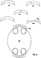
- the cartridge body 6 is also provided with four indentations 18 which acts as finger grips for a user.
- the upper end 12 of the cartridge body 6 is provided with two mounting lugs 20 which serve to mount the cartridge 2 in an appropriate appliance or receptacle.
- these lugs are generally arcuate in shape and as can be seen from Figures 3 and 8 they have a chamfered outer edge 22.
- the mounting lugs 20 are arranged aligned with the major axis of the cartridge body 6. The chamfered edge 22 acts to cam the cartridge into position when it is mounted, as will be discussed further below.
- the grille 10 comprises a generally planar base 24 which is provided with a plurality of slots 26 of the order of 0.25mm wide. Support ribs 26 extend across the slots 26 to prevent their deformation thereby preventing treatment particles escaping through the slots 26.
- the grille 10 is shown with slots 26, other shapes of opening may be provided instead of slots.
- the peripheral region 28 of the grill 10 is formed to extend upwardly at an angle from the planar base 24.
- the upper edge 30 of the peripheral region 28 snaps in behind a rib 32 extending around the internal surface of the container body 6.
- the base 24 of the grille 10 locates inside a raised rib 36 provided on the inside of the cartridge body 6.
- the cap 8 of the cartridge 2 has a downwardly depending flange 40 which fits inside the upper end 12 of the cartridge body 6.
- the cap 8 is welded, for example ultrasonically welded, to the upper part 12 of the cartridge body 6 in the region designated generally as 42.
- the upper surface 44 of the cap 8 has an outer region 46 free from any openings.
- a central region 48 is spaced from outer region 46 by an annular channel 50.
- the channel 50 has a radially outer wall 52, a radially inner wall 54 and a base 56.
- the lower part 58 of the radially outer wall 52 is provided around its entire periphery with a plurality of longitudinally extending slots 60. These slots are approximately 0.25mm wide.
- the upper region 62 of the wall 52 is, however, continuous and contains no such slots.
- the base 56 of the channel 50 is also continuous with no slots, as is the lower region 64 of the inner wall 54.
- an upper region 66 of the inner wall 54 is also provided with longitudinally extending slots 68 of the same dimensions as those slots 60 in the outer wall 52.
- the slots 68 do not extend to the upper surface 48 but terminate at a spacing therefrom.
- Four further vent slots 70 are provided in the surface 48.
- a cartridge 2 in accordance with the invention is intended to be received in the bottom of a water receiving receptacle 80.
- this receptacle comprises an outer wall 82, a base 84 and a depending flange 86.
- An opening 88 is formed centrally in the base 84 and a depending circular lip 90 formed around the opening 88.
- a circular sealing member 93 is mounted around the upper outer surface of the wall 90.
- the outer wall 86 is generally elliptical in shape and is formed with outwardly extending flanges 92 at opposed ends.
- the flanges 92 receive the mounting lugs 20 of the cartridge 2.
- the outer wall has two scalloped regions 96 adjacent the flanges 92 which can receive the lugs 20 which can then be turned in order to position the lugs over the flanges 92 and secure the cartridge 2 in position.
- the cartridge can be turned until the lug 20 engages an end surface 98 of the wall 86, as shown in Figure 10 .
- the act of rotating the cartridge 2 into position seals the cartridge 2 in position.
- the corner 100 between the walls 46 and 52 of the cartridge upper surface is brought into sealing engagement with the sealing ring 93 (see Fig. 13 ).
- the chamfer 22 (seen in Fig. 5 ) of the lug 20 pushes the cartridge 2 upwardly as it rotates over the edge 102 of the flange 92.
- the lug 20 will give different compression characteristics.
- the apparent angle of the chamfer 22 varies at different lateral and axial positions along the lug 20, so depending on where the lug first engages the surface 102, a steep ramp or a more prolonged ramp effect will occur. This can be used to give an appropriate compression characteristic for the particular seal used.
- outer wall 52 is tapered such that it guides the cartridge into position over the depending wall 90.
- the cartridge 2 is mounted to a mount 150 which can, for example, be a mounting member provided in an upper region of a water heating vessel such as a kettle or hot water jug.
- the mount in this embodiment not only receives the cartridge 2 but also a receptacle 152 which contained water and which has a valve 154 which remains closed until such time as a receptacle 152 is placed down on the mounting plate 150.
- the lower surface of the mount 150 is substantially similar to that of the lower surface of the receptacle in the earlier described embodiment and further details would need not, therefore, be given.
- the mount 150 comprises a central circular opening 156 which receives a downwardly depending wall 158 of the receptacle 152.
- the opening 156 of the mount 150 is surrounded by an inverted U-shaped wall 160 which mounts within its channel a fin seal 162 which extends radially inwardly.
- the valve 154 is positioned such that it will not open until a seal is made between the fin seal 162 and wall 158. Once that occurs, the bottom end 166 of the valve contacts the surface 48 of the cartridge 2 forcing the valve member upwardly to allow water to flow from the receptacle into the cartridge 2.
- Figure 15 shows an arrangement in which the water receptacle 200 has a major and a minor access.
- Figure 16 shows a cartridge 2 mounted in a cordless liquid heating appliance 300.
- the mount for the cartridge 2 is formed in the lid 302 of a liquid heating vessel 304 which receives a hopper 306 for untreated water.
- the detail of interengagement of the cartridge, mount and hopper is the same as shown in Figure 14 .
- Figure 17 shows a first arrangement in which a key 250 may be positioned in positions A, B, C and D on a peripheral part of the cartridge 2.
- a corresponding opening will be provided in a flange of the receptacle base in order to receive only cartridges which have the key 250 in the appropriate position.
- the shape of the mounting lug may be different for different cartridges.
- the mounting lug may take a number of different forms, 300, 302, 304, 306 and 308.
- a correspondingly shaped opening in the wall of the mounting plate or receptacle will be provided for each of these.
- key 308 will fit all the openings in the receptacle body and be regarded as a master key.
- Figure 19 shows yet a further concept in which the mounting lug 400 may be provided with notches 402, 404, 406 or 408, as shown, with the corresponding part of the receptacle having corresponding pegs to receive the notches.
- Figure 20 shows an arrangement in which keying lugs 500 are provided on the wall 52 of the cartridge 2, with the corresponding wall 90 being provided with cut outs 502 to receive those lugs.
- cartridge body Other shapes are possible.
- a rectangular section body could be suitably blended into the elliptical mounting part of the cartridge shown in Figure 1 .
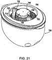
- Figure 21 shows a further cartridge in accordance with the invention.
- the cartridge 700 is substantially the same as that shown in Figure 1 .
- a pair of ribs 702 extend across the annular channel 704 in the cartridge top.
- the ribs 702 extend upwardly from the base of the channel and are hollow so as to allow trapped air to move towards the vents 708 from the region under the base of the channel and the region radially outwardly of the channel.
- the slots 710 in the inner wall of the channel extend to the base of the channel.
- the depending wall 90 of the base 84 onto which the cartridge fits can be reduced in height or removed altogether at least in the region of the ribs 702 to allow the cartridge to be mounted in position.
- the cartridge body 6 and preferably the entire cartridge 2 is made of a plastic which is both heat resistant and resistant to gamma radiation, such as Samsung HJ730+ and Basell Moplen HP371(Gamma Stabilised) to prevent discolouring of the plastic material during use.
- a plastic which is both heat resistant and resistant to gamma radiation
- the cartridge body 6 at least could also be made from metal, for example, with the cap made of plastics, as before.
Landscapes
- Chemical & Material Sciences (AREA)
- Chemical Kinetics & Catalysis (AREA)
- Engineering & Computer Science (AREA)
- Environmental & Geological Engineering (AREA)
- Life Sciences & Earth Sciences (AREA)
- Hydrology & Water Resources (AREA)
- Food Science & Technology (AREA)
- Water Supply & Treatment (AREA)
- Organic Chemistry (AREA)
- Water Treatment By Sorption (AREA)
- Treatment Of Water By Ion Exchange (AREA)
- Cookers (AREA)
- Physical Water Treatments (AREA)
- Biological Treatment Of Waste Water (AREA)
- External Artificial Organs (AREA)
Claims (45)
- Montageteil einer oder für eine Wasserbehandlungspatrone (2; 700), wobei das Montageteil Montagenasen (20) und eine kreisförmige Dichtungsoberfläche, die radial innerhalb der Montagenasen (20) angeordnet ist, besitzt, dadurch gekennzeichnet, dass das Montageteil in einem horizontalen Querschnitt eine Hauptachse und eine Nebenachse besitzt und die Montagenasen (20) sich vom Umfang des Montageteils erstrecken und in einer Längsrichtung, die auf die Hauptachse des Montageteils ausgerichtet ist, an gegenüberliegenden Enden des Montageteils angeordnet sind.
- Montageteil nach Anspruch 1, wobei die Montagenasen (20) eine gekrümmte Form haben.
- Montageteil nach Anspruch 1 oder 2, wobei die Montageteile (20) dazu ausgelegt sind, eine Patrone in einem Bajonettanschluss zu montieren.
- Montageteil nach Anspruch 1, 2 oder 3, wobei die Montagenasen (20) aus einem Kunststoff hergestellt sind.
- Montageteil nach Anspruch 4, wobei der Kunststoff ein wärmebeständiger Kunststoff ist.
- Montageteil nach Anspruch 4 oder 5, wobei der Kunststoff gegenüber einer Verschlechterung durch Gammastrahlung beständig ist.
- Wasserbehandlungsgerät, das eine Wasserbehandlungspatrone (2; 700) aufweist, die durch ein Montageteil nach einem vorhergehenden Anspruch montiert ist, wobei das Gerät eine nach unten hängende Wand (90) und eine Dichtung (93), die an der nach außen weisenden Oberfläche der Wand (90) montiert ist, um mit der kreisförmigen Dichtungsoberfläche in Eingriff zu gelangen, aufweist, wobei die Unterkante des Nasenumfangs angefast ist, so dass dann, wenn die Montagenasen (20) auf eine Aufnahmeoberfläche gedreht werden, die Fase (22) als Nocken für die Patrone (2; 700) wirkt, damit diese in einen Dichtungseingriff mit der Dichtung (93) gelangt.
- Wasserbehandlungspatrone mit einem Montageteil nach einem der Ansprüche 1-6, das damit einteilig ausgebildet ist oder ein getrenntes Element ist.
- Wasserbehandlungspatrone nach Anspruch 8, wobei die Wasserbehandlungspatrone (2-7) einen Patronenkörper (6) aufweist, der an seinem oberen Ende (12) durch eine Kappe (8) verschlossen ist, die Wassereinlassöffnungen (60, 68) enthält, während im unteren Ende des Patronenkörpers (6) eine Auslassöffnung (16) vorgesehen ist, wobei die Patrone (2; 700) in einem horizontalen Querschnitt eine Hauptachse und eine Nebenachse besitzt, wobei die Montagenasen (20) am oberen Ende (12) der Patrone (2; 700) vorgesehen sind und sich vom Umfang der Patrone (2; 700) erstrecken und auf die Hauptachse der Patrone (2; 700) ausgerichtet sind.
- Wasserbehandlungspatrone nach Anspruch 9, wobei der Patronenkörper (6) oder zumindest ihr Montageteil im horizontalen Querschnitt elliptisch ist.
- Wasserbehandlungspatrone nach einem der Ansprüche 8-10, wobei die Montagenasen (20) eben sind und sich über wenigstens 15° um den Umfang der Patrone (2; 700) erstrecken.
- Wasserbehandlungspatrone nach einem der Ansprüche 8-11, wobei die Montagenasen (20) eine gekrümmte Form haben.
- Wasserbehandlungspatrone nach einem der Ansprüche 8-12, wobei die Montagenasen (20) dazu ausgelegt sind, die Patrone (2; 700) in einem Bajonettanschluss zu montieren.
- Wasserbehandlungspatrone nach einem der Ansprüche 8-13, wobei die Patrone (2; 700) oder wenigstens deren Nasen (20) aus einem Kunststoff hergestellt sind.
- Wasserbehandlungspatrone nach Anspruch 14, wobei der Kunststoff ein wärmebeständiger Kunststoff ist.
- Wasserbehandlungspatrone nach Anspruch 14 oder 15, wobei der Kunststoff gegenüber einer Verschlechterung durch Gammastrahlung beständig ist.
- Wasserbehandlungspatrone nach einem der Ansprüche 8-16, wobei die kreisförmige Dichtungsoberfläche wenigstens teilweise durch wenigstens einen Abschnitt einer nach innen weisenden und nach unten sich erstreckenden Wand (52) gebildet ist.
- Wasserbehandlungspatrone nach Anspruch 17, wobei die Dichtungsoberfläche um die Ecke (100) zwischen einer nach oben weisenden Oberfläche (46) und einer nach innen weisenden Oberfläche (52) des oberen Teils der Patrone (2; 700) geformt ist.
- Wasserbehandlungspatrone nach Anspruch 18, wobei die Ecke (100) abgerundet oder angefast ist.
- Wasserbehandlungspatrone nach einem der Ansprüche 17-19, wobei sich die nach innen weisende Wand (52) von oben nach unten einwärts konisch verjüngt.
- Wasserbehandlungspatrone nach einem der Ansprüche 17-20, wobei die einwärts weisende Wand (52) die radial äußere Wand eines ringförmigen Kanals (50; 704) bildet, der sich um die Oberseite der Patrone (2; 700) erstreckt.
- Wasserbehandlungspatrone nach Anspruch 21, wobei in der einwärts weisenden Wand (52) Wassereinlassöffnungen (60) vorgesehen sind.
- Wasserbehandlungspatrone nach Anspruch 22, wobei die Wassereinlassöffnungen (68) auch in der radial inneren und auswärts weisenden Wand (54) des Kanals (50; 704) vorgesehen sind.
- Wasserbehandlungspatrone nach Anspruch 23, wobei die innere Wand (54) eine kleinere Öffnungsfläche als die äußere Wand (54) hat.
- Wasserbehandlungspatrone nach Anspruch 23 oder 24, wobei die Einlassöffnungen (60, 68) in einem unteren Teil der äußeren Wand (52) und in einem oberen Teil der inneren Wand (54) vorgesehen sind.
- Wasserbehandlungspatrone nach einem der Ansprüche 21-25, wobei an der Oberseite der umschlossenen Fläche des ringförmigen Kanals (50; 704) Belüftungsöffnungen (708) vorgesehen sind.
- Wasserbehandlungspatrone nach einem der Ansprüche 21-26, wobei sich über den ringförmigen Kanal (50; 704) ein oder mehrere Stege erstrecken.
- Wasserbehandlungspatrone nach einem der Ansprüche 9-27, die ferner ein an der Unterseite des Patronenkörpers (6) vorgesehenes Gitter (10) aufweist.
- Wasserbehandlungspatrone nach Anspruch 28, wobei das Gitter (10) Behandlungspartikel von einer verengten Öffnung (16) in der Basis des Patronenkörpers (6) abhält.
- Wasserbehandlungspatrone nach Anspruch 29, wobei das Gitter (10) in den Patronenkörper (6) eingerastet ist, der seinerseits mit geeigneten Rückhaltemitteln versehen ist, beispielsweise mit einer an seiner Innenoberfläche ausgebildeten Rückhaltelippe.
- Wasserbehandlungspatrone nach Anspruch 28, 29 oder 30, wobei das Gitter (10) mit einem nach oben konkaven äußeren Abschnitt ausgebildet ist, in dem sich Luft eher als auf der Gitteroberfläche ansammelt und der dann, wenn er im Patronenkörper (6) angeordnet ist, von dem Patronenkörper (6) beabstandet ist, so dass zwischen dem Patronenkörper (6) und dem konkaven Abschnitt des Gitters (10) Luft entweichen kann.
- Wasserbehandlungspatrone nach einem der Ansprüche 9-31, wobei sich der Patronenkörper (6) von der Oberseite zur Unterseite der Patrone (2; 700) gekrümmt konisch verjüngt.
- Wasserbehandlungspatrone nach Anspruch 32, wobei der Verjüngungskonus auf die Hauptachse der Patrone (2; 700) ausgerichtet ist.
- Wasserbehandlungspatrone nach Anspruch 32 oder 33, wobei sich die Krümmung im Wesentlichen zur Mittellinie der Patrone (2; 700) erstreckt.
- Wasserbehandlungspatrone nach Anspruch 32 oder 33, wobei sowohl die vordere als auch die hintere Wand der Patrone (2; 700) auf diese Weise konisch verjüngt sind.
- Wasserbehandlungspatrone nach einem der Ansprüche 8-35, wobei an der Patrone (2) Mittel vorgesehen sind, die verhindern, dass die Patrone (2) in einem nicht geeigneten Gerät verwendet wird.
- Wasserbehandlungspatrone nach Anspruch 36, wobei in einem Abschnitt der Patrone (2) ein oder mehrere Keile vorgesehen sind und wobei der eine oder die mehreren Keile (250) auf einer Umfangsoberfläche der Patrone (2) vorgesehen sind oder wobei der eine oder die mehreren Keile in einer Montagenase (300, 302, 304, 306, 308; 400) für die Patrone (2) vorgesehen sind oder wobei der eine oder die mehreren Keile (500) an einer inneren Wand (52) der Patrone (2) vorgesehen sind.
- Wasserbehandlungspatrone nach einem der Ansprüche 8-37, wobei der Patrone (2; 700) ein Zähler zugeordnet ist, der verwendet werden kann, um den Nutzungsgrad der Patrone (2; 700) anzugeben.
- Wasserbehandlungspatrone nach Anspruch 38, wobei die Patrone (2; 700) mit Mitteln versehen ist, die bei einer Drehung der Patrone (2; 700) in ihre oder aus ihrer Stellung mit einem Aktor in Eingriff gelangen, um den Nutzungszähler zurückzusetzen.
- Wasserbehandlungspatrone nach einem der Ansprüche 8-39, wobei die Patrone (2; 700) außerdem einen Partikelfilter enthält.
- Flüssigkeitsheizgerät, das eine Wasserbehandlungspatrone (2) nach einem der Ansprüche 8-40, Mittel, die an der Patrone (2) und an einem Montageort für die Patrone (2) vorgesehen sind, um zu verhindern, dass eine ungeeignete Patrone in dem Gerät montiert wird, enthält.
- Flüssigkeitsheizgerät nach Anspruch 41, wobei in einem Abschnitt der Patrone (2) ein oder mehrere Keile (250; 300, 302, 304, 306, 308; 400; 500) vorgesehen sind und ein komplementärer Keil in dem Montageort vorgesehen ist.
- Wasserbehandlungsgerät, das eine Wasserbehandlungspatrone nach einem der Ansprüche 8-40 besitzt, wobei das Gerät einen Zähler, der die Nutzung der Patrone (2; 700) angibt, und einen Aktor, um den Zähler automatisch zurückzusetzen, wenn die Patrone (2; 700) entfernt oder ausgetauscht wird, enthält.
- Wasserbehandlungsvorrichtung mit einer Wasserbehandlungspatrone (2) nach einem der Ansprüche 8-40, die in einem Wasseraufnahmegefäß (80; 200; 304) montiert ist, das einen Trichter (152; 306), der nicht behandeltes Wasser enthält, aufnimmt, wobei der Trichter (152; 306) Ventilmittel (154) besitzt, die durch eine obere Oberfläche der Patrone (2) geöffnet werden, wenn der Trichter (152; 306) auf dem Gefäß (80; 200; 304) angeordnet wird.
- Wasserbehandlungsgerät, das eine Kammer für die Aufnahme unbehandelten Wassers aufweist, wobei die Kammer eine Ausflussöffnung besitzt und eine Wasserbehandlungspatrone (2) nach einem der Ansprüche 8-40 besitzt, die in einer Fluidkommunikation mit der Öffnung montiert ist, um Wasser von der Kammer für die Behandlung aufzunehmen.
Priority Applications (1)
| Application Number | Priority Date | Filing Date | Title |
|---|---|---|---|
| EP11191061A EP2436431A3 (de) | 2002-08-07 | 2003-08-07 | Wasserbehandlungsvorrichtung |
Applications Claiming Priority (3)
| Application Number | Priority Date | Filing Date | Title |
|---|---|---|---|
| GB0218318 | 2002-08-07 | ||
| GBGB0218318.4A GB0218318D0 (en) | 2002-08-07 | 2002-08-07 | Water treatment apparatus |
| PCT/GB2003/003471 WO2004014519A2 (en) | 2002-08-07 | 2003-08-07 | Water treatment apparatus |
Related Child Applications (1)
| Application Number | Title | Priority Date | Filing Date |
|---|---|---|---|
| EP11191061.8 Division-Into | 2011-11-29 |
Publications (2)
| Publication Number | Publication Date |
|---|---|
| EP1526909A2 EP1526909A2 (de) | 2005-05-04 |
| EP1526909B1 true EP1526909B1 (de) | 2012-05-02 |
Family
ID=9941885
Family Applications (2)
| Application Number | Title | Priority Date | Filing Date |
|---|---|---|---|
| EP11191061A Withdrawn EP2436431A3 (de) | 2002-08-07 | 2003-08-07 | Wasserbehandlungsvorrichtung |
| EP03784277A Expired - Lifetime EP1526909B1 (de) | 2002-08-07 | 2003-08-07 | Vorrichtung zur wasserreinigung |
Family Applications Before (1)
| Application Number | Title | Priority Date | Filing Date |
|---|---|---|---|
| EP11191061A Withdrawn EP2436431A3 (de) | 2002-08-07 | 2003-08-07 | Wasserbehandlungsvorrichtung |
Country Status (16)
| Country | Link |
|---|---|
| US (1) | US8454826B2 (de) |
| EP (2) | EP2436431A3 (de) |
| JP (1) | JP4642464B2 (de) |
| KR (1) | KR20050069981A (de) |
| CN (3) | CN100593430C (de) |
| AT (1) | ATE555837T1 (de) |
| AU (1) | AU2003251372B2 (de) |
| DE (1) | DE20380258U1 (de) |
| ES (1) | ES2389152T3 (de) |
| GB (1) | GB0218318D0 (de) |
| MX (1) | MXPA04012734A (de) |
| PL (1) | PL212908B1 (de) |
| PT (1) | PT1526909E (de) |
| RU (1) | RU2335327C2 (de) |
| WO (2) | WO2004014519A2 (de) |
| ZA (1) | ZA200409949B (de) |
Families Citing this family (33)
| Publication number | Priority date | Publication date | Assignee | Title |
|---|---|---|---|---|
| US7476314B2 (en) | 2000-08-11 | 2009-01-13 | Reid Roger P | Keyed system for connection of filter cartridge to filter holder |
| US9314722B2 (en) | 2000-08-11 | 2016-04-19 | Omnipure Filter Company, Inc. | Keyed system for connection of filter cartridge to filter holder |
| US20110203985A1 (en) * | 2009-08-21 | 2011-08-25 | Omnipure Filter Company, Pllc | Keyed system for connection of filter to filter holder |
| DE102004026188A1 (de) * | 2004-05-28 | 2005-12-29 | Brita Gmbh | Filterkatusche und Vorrichtung zur Filtration von Flüssigkeiten |
| DE102004026167A1 (de) * | 2004-05-28 | 2005-12-22 | Brita Gmbh | Filterkartusche und Vorrichtung zur Filtration von Flüssigkeiten |
| DE102004026166B3 (de) * | 2004-05-28 | 2006-02-09 | Brita Gmbh | Filterkartusche und Vorrichtung zur Filtration von Flüssigkeiten |
| GB0427825D0 (en) * | 2004-12-17 | 2005-01-19 | Strix Ltd | Water treatment vessels and cartridges therefor |
| US8252180B2 (en) | 2006-08-10 | 2012-08-28 | Aquis Wasser-Luft-Systeme Gmbh, Lindau, Zweigniederlassung Rebstein | Tank |
| DE202007002786U1 (de) * | 2007-02-22 | 2008-06-26 | Mann+Hummel Gmbh | Fluidfilter mit einem in ein Filtergehäuse einsetzbaren Filterelement |
| DE102008015112B9 (de) | 2008-03-20 | 2010-08-12 | Brita Gmbh | Behälter für die Filtration von Flüssigkeit |
| DE102009000231B4 (de) * | 2009-01-14 | 2020-11-19 | Brita Gmbh | Ventilbetätigungseinrichtung eines Ventils, Flüssigkeitsbehälter einer Flüssigkeitsbehandlungsvorrichtung, Flüssigkeitsbehandlungsvorrichtung sowie Verwendung einer solchen Vorrichtung |
| USD712007S1 (en) | 2010-03-03 | 2014-08-26 | Omnipure Filter Company, Inc. | Filter for liquid |
| CN103068741B (zh) | 2010-08-12 | 2014-09-10 | 三菱丽阳可菱水株式会社 | 开口部结构以及净水滤筒 |
| DE102010041664A1 (de) | 2010-09-29 | 2012-03-29 | Brita Gmbh | Vorrichtung zum Behandeln einer Flüssigkeit |
| DE102010063088B3 (de) * | 2010-12-14 | 2012-02-23 | Brita Gmbh | Vorrichtung zum Behandeln einer Flüssigkeit |
| GB201107428D0 (en) | 2011-05-04 | 2011-06-15 | Strix Ltd | Water treatment apparatus |
| GB201107426D0 (en) * | 2011-05-04 | 2011-06-15 | Strix Ltd | Water treatment apparatus |
| KR101343933B1 (ko) | 2011-09-08 | 2014-01-15 | 유한회사 신정알앤디 | 무동력 초기우수 처리장치 |
| EP2570166B1 (de) * | 2011-09-15 | 2020-05-20 | Whirlpool Corporation | Wasserfiltersystem mit einer elektronischen Schnittstelle und Verfahren zur Installation einer Filtereinheit |
| US8950052B2 (en) | 2011-09-15 | 2015-02-10 | Whirlpool Corporation | Method of installing a filter unit |
| US8845896B2 (en) | 2011-09-15 | 2014-09-30 | Whirlpool Corporation | Water filter system |
| US20130068684A1 (en) | 2011-09-15 | 2013-03-21 | Whirlpool Corporation | Filter unit |
| WO2013044079A1 (en) | 2011-09-21 | 2013-03-28 | Hydros Bottle, Llc | Water bottle |
| DE102012210830A1 (de) * | 2012-06-26 | 2014-01-02 | Wmf Württembergische Metallwarenfabrik Ag | Vorrichtung zur Wasserreinigung |
| CA2999505C (en) | 2015-09-24 | 2024-01-23 | Hydros Bottle, Llc | Gravity-flow filter assembly |
| CN106361142A (zh) * | 2016-11-08 | 2017-02-01 | 天津市山谷环保科技有限公司 | 一种底部上水防干烧的电热水壶 |
| USD877565S1 (en) | 2017-03-23 | 2020-03-10 | Hydros Bottle, Llc | Container with a cap and filter assembly |
| WO2018175786A1 (en) | 2017-03-23 | 2018-09-27 | Hydros Bottle, Llc | Gravity-flow filter assembly |
| US10525387B2 (en) | 2017-04-06 | 2020-01-07 | Whirlpool Corporation | Filter cartridge |
| US10584040B2 (en) | 2017-10-06 | 2020-03-10 | Whirlpool Corporation | Filter cartridge |
| DE202017006743U1 (de) | 2017-11-30 | 2018-05-17 | Robert Bosch Gmbh | Strukturelemente, Gehäusestruktur und Heizvorrichtung |
| US10807025B2 (en) | 2018-08-06 | 2020-10-20 | Whirlpool Corporation | Blind attachment interface for filter housing assembly |
| US12005408B1 (en) | 2023-04-14 | 2024-06-11 | Sharkninja Operating Llc | Mixing funnel |
Family Cites Families (41)
| Publication number | Priority date | Publication date | Assignee | Title |
|---|---|---|---|---|
| US691655A (en) * | 1901-07-20 | 1902-01-21 | John F Malloy | Water-cooler. |
| DE8525643U1 (de) * | 1985-10-05 | 1987-01-22 | Alhäuser, Erich, 5412 Ransbach-Baumbach | Drucklos arbeitendes Gerät zum Verbessern der Qualität von Trinkwasser |
| DE8808609U1 (de) * | 1988-07-05 | 1989-12-14 | Surex GmbH, 6204 Taunnusstein | Filtereinsatz |
| US5076922A (en) * | 1990-10-12 | 1991-12-31 | Wilton Industries, Inc. | Water-filtration apparatus |
| JPH04363191A (ja) | 1991-02-28 | 1992-12-16 | Matsushita Electric Works Ltd | 浄水装置 |
| CA2098127C (en) * | 1993-06-10 | 1997-03-18 | Brian Feeney | Air inlet valve for water cooler |
| FR2708452B1 (fr) * | 1993-07-29 | 1997-09-05 | Moulinex Sa | Machine à infusion comportant un dispositif de purification d'eau. |
| JPH0725988U (ja) * | 1993-10-25 | 1995-05-16 | アップルウェアー株式会社 | 浄水容器 |
| JPH07171558A (ja) * | 1993-12-16 | 1995-07-11 | Toray Ind Inc | 浄水器及び浄水器用タワー |
| US5525214A (en) * | 1994-03-08 | 1996-06-11 | Recovery Engineering, Inc. | Filter cartridge for water treatment device |
| US5469708A (en) * | 1994-09-23 | 1995-11-28 | Harrison; Howard R. | Water cooler |
| JP3069267B2 (ja) * | 1995-04-17 | 2000-07-24 | 大日興産株式会社 | シール部の構造 |
| US5591332A (en) * | 1995-05-25 | 1997-01-07 | Omnipure Filter Co. | Filter assembly with automatic shut-off and quick-connect filter cartridge |
| CN2258196Y (zh) * | 1995-12-13 | 1997-07-23 | 朱国柱 | 水龙头净水器 |
| US5609033A (en) * | 1996-01-16 | 1997-03-11 | Chung Ho Nais Incorporation | Water cooling device for water purifiers |
| US5811004A (en) * | 1996-04-30 | 1998-09-22 | Syratech Corporation | Water filtration cartridge |
| US5882507A (en) | 1996-04-30 | 1999-03-16 | Recovery Engineering, Inc. | Water filter cartridge end-of-life mechanism |
| JPH1034138A (ja) | 1996-07-20 | 1998-02-10 | Bridgestone Corp | 冷却機能を備えた浄水器 |
| US20020036162A1 (en) * | 1996-08-08 | 2002-03-28 | Magnusson Jan H. | Appliance with iodinated water source |
| US5753107A (en) * | 1996-08-08 | 1998-05-19 | Wtc Ecomaster Corporation | Dripless purification manifold and cartridge |
| DE69721176T2 (de) | 1996-10-16 | 2004-03-25 | Thermovonics Co. Ltd., Kawasaki | Wasserkühler |
| US5842353A (en) * | 1996-12-13 | 1998-12-01 | Kuo-Liang; Lin | Apparatus for heating or cooling drinks |
| US5873995A (en) * | 1997-05-06 | 1999-02-23 | The Clorox Company | End-of-life indicator for water treatment device |
| JPH10328658A (ja) * | 1997-05-30 | 1998-12-15 | Samsung Electron Co Ltd | 水分配器 |
| JPH1183271A (ja) | 1997-09-05 | 1999-03-26 | Bridgestone Corp | 冷水器 |
| US6103114A (en) * | 1998-01-09 | 2000-08-15 | Recovery Engineering, Inc. | Pour-through water treatment carafe |
| PL348456A1 (en) * | 1998-01-21 | 2002-05-20 | Clorox Co | Faucet mounted water filter |
| US6237345B1 (en) * | 1998-04-17 | 2001-05-29 | Home Pure L.L.C. | Water cooler and dispenser |
| US6003318A (en) * | 1998-04-28 | 1999-12-21 | Oasis Corporation | Thermoelectric water cooler |
| US6099735A (en) * | 1998-06-04 | 2000-08-08 | Kelada; Maher I. | Counter top reverse osmosis water purification system |
| DE19861175B4 (de) * | 1998-10-09 | 2005-01-05 | Brita Gmbh | Wasserfiltervorrichtung mit einer Auffangkanne und mit Heizelement |
| IL132316A0 (en) * | 1999-10-11 | 2001-03-19 | Fitoussi Mayer | Water purification device |
| DE60030455T3 (de) | 1999-12-23 | 2011-05-05 | Strix Ltd. | Elektischer wassererhitzer |
| US6953526B1 (en) * | 2000-03-22 | 2005-10-11 | Cuno Incorporated | Filter assembly |
| WO2002000552A2 (en) | 2000-06-23 | 2002-01-03 | Innova/Pure Water, Inc. | Water-filter lifetime indicator |
| WO2002026615A1 (en) | 2000-09-26 | 2002-04-04 | Oasis Corporation | Removable reservoir cooler |
| IT1318965B1 (it) * | 2000-10-04 | 2003-09-19 | Adriana Brizio | Caffettiera. |
| CA2432899C (en) * | 2000-12-25 | 2009-07-21 | Mitsubishi Rayon Co., Ltd. | Pitcher type water purifier and purification cartridge for the water purifier |
| GB0116878D0 (en) * | 2001-07-11 | 2001-09-05 | Timestrip Ltd | Time indicator |
| US6651824B2 (en) | 2001-08-17 | 2003-11-25 | Dart Industries Inc. | Filter pitcher with ice hopper |
| RU2004129624A (ru) * | 2003-10-03 | 2006-03-10 | Стрикс Лимитед (Gb) | Сосуд для хранения воды |
-
2002
- 2002-08-07 GB GBGB0218318.4A patent/GB0218318D0/en not_active Ceased
-
2003
- 2003-08-07 CN CN03816043A patent/CN100593430C/zh not_active Expired - Lifetime
- 2003-08-07 PL PL373770A patent/PL212908B1/pl unknown
- 2003-08-07 CN CN2010100004428A patent/CN101844818B/zh not_active Expired - Lifetime
- 2003-08-07 MX MXPA04012734A patent/MXPA04012734A/es active IP Right Grant
- 2003-08-07 EP EP11191061A patent/EP2436431A3/de not_active Withdrawn
- 2003-08-07 ES ES03784277T patent/ES2389152T3/es not_active Expired - Lifetime
- 2003-08-07 US US10/523,848 patent/US8454826B2/en not_active Expired - Fee Related
- 2003-08-07 EP EP03784277A patent/EP1526909B1/de not_active Expired - Lifetime
- 2003-08-07 CN CNU039000087U patent/CN2806429Y/zh not_active Expired - Lifetime
- 2003-08-07 DE DE20380258U patent/DE20380258U1/de not_active Expired - Lifetime
- 2003-08-07 RU RU2004136288/15A patent/RU2335327C2/ru active
- 2003-08-07 AU AU2003251372A patent/AU2003251372B2/en not_active Ceased
- 2003-08-07 WO PCT/GB2003/003471 patent/WO2004014519A2/en not_active Ceased
- 2003-08-07 WO PCT/GB2003/003446 patent/WO2004014801A2/en not_active Ceased
- 2003-08-07 JP JP2004527044A patent/JP4642464B2/ja not_active Expired - Fee Related
- 2003-08-07 KR KR1020057002307A patent/KR20050069981A/ko not_active Ceased
- 2003-08-07 PT PT03784277T patent/PT1526909E/pt unknown
- 2003-08-07 AT AT03784277T patent/ATE555837T1/de active
-
2004
- 2004-12-08 ZA ZA200409949A patent/ZA200409949B/xx unknown
Also Published As
| Publication number | Publication date |
|---|---|
| WO2004014519A8 (en) | 2005-03-24 |
| PL212908B1 (pl) | 2012-12-31 |
| PT1526909E (pt) | 2012-06-01 |
| EP2436431A2 (de) | 2012-04-04 |
| RU2335327C2 (ru) | 2008-10-10 |
| JP4642464B2 (ja) | 2011-03-02 |
| CN2806429Y (zh) | 2006-08-16 |
| CN100593430C (zh) | 2010-03-10 |
| WO2004014519A2 (en) | 2004-02-19 |
| RU2004136288A (ru) | 2005-07-10 |
| JP2005534491A (ja) | 2005-11-17 |
| US8454826B2 (en) | 2013-06-04 |
| WO2004014519A3 (en) | 2004-09-23 |
| ES2389152T3 (es) | 2012-10-23 |
| PL373770A1 (en) | 2005-09-19 |
| EP1526909A2 (de) | 2005-05-04 |
| GB0218318D0 (en) | 2002-09-11 |
| CN101844818B (zh) | 2012-11-21 |
| WO2004014801A2 (en) | 2004-02-19 |
| WO2004014801A3 (en) | 2004-10-28 |
| US20060169629A1 (en) | 2006-08-03 |
| AU2003251372A1 (en) | 2004-02-25 |
| MXPA04012734A (es) | 2005-08-15 |
| KR20050069981A (ko) | 2005-07-05 |
| CN1665580A (zh) | 2005-09-07 |
| ZA200409949B (en) | 2006-02-22 |
| ATE555837T1 (de) | 2012-05-15 |
| DE20380258U1 (de) | 2005-04-07 |
| EP2436431A3 (de) | 2012-07-11 |
| CN101844818A (zh) | 2010-09-29 |
| AU2003251372B2 (en) | 2009-07-23 |
Similar Documents
| Publication | Publication Date | Title |
|---|---|---|
| EP1526909B1 (de) | Vorrichtung zur wasserreinigung | |
| AU2003251372A2 (en) | Water treatment apparatus | |
| AU747674B2 (en) | Water filter device having a collecting pot and a heating element | |
| CN1277498C (zh) | 液体处理过滤器、液体处理盒以及液体加热器具 | |
| JP2022153425A (ja) | 重力流式フィルタアセンブリ | |
| CA3064754A1 (en) | Liquid container lid assembly | |
| TW201121632A (en) | Water treatment cartridge | |
| US5012059A (en) | Appliance for heating water by microwave power | |
| GB2517485A (en) | Appliances and components therefor | |
| TW201127706A (en) | Bottle for water treatment device | |
| EP2704994B1 (de) | Vorrichtung zur wasseraufbereitung | |
| CN103582613B (zh) | 水处理设备 | |
| EP0804114A1 (de) | Wasserkocher | |
| JP2025010173A (ja) | 茶こし付き飲用ボトル | |
| KR100832448B1 (ko) | 물 처리 장치 | |
| KR100832446B1 (ko) | 물 처리 장치 | |
| WO2024038274A1 (en) | Water treatment devices and liquid heating devices |
Legal Events
| Date | Code | Title | Description |
|---|---|---|---|
| PUAI | Public reference made under article 153(3) epc to a published international application that has entered the european phase |
Free format text: ORIGINAL CODE: 0009012 |
|
| 17P | Request for examination filed |
Effective date: 20041201 |
|
| AK | Designated contracting states |
Kind code of ref document: A2 Designated state(s): AT BE BG CH CY CZ DE DK EE ES FI FR GB GR HU IE IT LI LU MC NL PT RO SE SI SK TR |
|
| AX | Request for extension of the european patent |
Extension state: AL LT LV MK |
|
| DAX | Request for extension of the european patent (deleted) | ||
| 111Z | Information provided on other rights and legal means of execution |
Free format text: ATBEBGCHCYCZDEDKEEESFIFRGBGRHUIEITLUMCNLPTROSESISKTR Effective date: 20050822 |
|
| 17Q | First examination report despatched |
Effective date: 20091119 |
|
| GRAP | Despatch of communication of intention to grant a patent |
Free format text: ORIGINAL CODE: EPIDOSNIGR1 |
|
| GRAS | Grant fee paid |
Free format text: ORIGINAL CODE: EPIDOSNIGR3 |
|
| GRAA | (expected) grant |
Free format text: ORIGINAL CODE: 0009210 |
|
| AK | Designated contracting states |
Kind code of ref document: B1 Designated state(s): AT BE BG CH CY CZ DE DK EE ES FI FR GB GR HU IE IT LI LU MC NL PT RO SE SI SK TR |
|
| REG | Reference to a national code |
Ref country code: GB Ref legal event code: FG4D |
|
| REG | Reference to a national code |
Ref country code: CH Ref legal event code: EP Ref country code: AT Ref legal event code: REF Ref document number: 555837 Country of ref document: AT Kind code of ref document: T Effective date: 20120515 |
|
| REG | Reference to a national code |
Ref country code: IE Ref legal event code: FG4D |
|
| REG | Reference to a national code |
Ref country code: PT Ref legal event code: SC4A Free format text: AVAILABILITY OF NATIONAL TRANSLATION Effective date: 20120524 |
|
| REG | Reference to a national code |
Ref country code: DE Ref legal event code: R096 Ref document number: 60340836 Country of ref document: DE Effective date: 20120621 |
|
| REG | Reference to a national code |
Ref country code: NL Ref legal event code: T3 |
|
| REG | Reference to a national code |
Ref country code: ES Ref legal event code: FG2A Ref document number: 2389152 Country of ref document: ES Kind code of ref document: T3 Effective date: 20121023 |
|
| PG25 | Lapsed in a contracting state [announced via postgrant information from national office to epo] |
Ref country code: FI Free format text: LAPSE BECAUSE OF FAILURE TO SUBMIT A TRANSLATION OF THE DESCRIPTION OR TO PAY THE FEE WITHIN THE PRESCRIBED TIME-LIMIT Effective date: 20120502 Ref country code: CY Free format text: LAPSE BECAUSE OF FAILURE TO SUBMIT A TRANSLATION OF THE DESCRIPTION OR TO PAY THE FEE WITHIN THE PRESCRIBED TIME-LIMIT Effective date: 20120502 Ref country code: SE Free format text: LAPSE BECAUSE OF FAILURE TO SUBMIT A TRANSLATION OF THE DESCRIPTION OR TO PAY THE FEE WITHIN THE PRESCRIBED TIME-LIMIT Effective date: 20120502 |
|
| REG | Reference to a national code |
Ref country code: AT Ref legal event code: MK05 Ref document number: 555837 Country of ref document: AT Kind code of ref document: T Effective date: 20120502 |
|
| PG25 | Lapsed in a contracting state [announced via postgrant information from national office to epo] |
Ref country code: SI Free format text: LAPSE BECAUSE OF FAILURE TO SUBMIT A TRANSLATION OF THE DESCRIPTION OR TO PAY THE FEE WITHIN THE PRESCRIBED TIME-LIMIT Effective date: 20120502 Ref country code: GR Free format text: LAPSE BECAUSE OF FAILURE TO SUBMIT A TRANSLATION OF THE DESCRIPTION OR TO PAY THE FEE WITHIN THE PRESCRIBED TIME-LIMIT Effective date: 20120803 |
|
| PG25 | Lapsed in a contracting state [announced via postgrant information from national office to epo] |
Ref country code: BE Free format text: LAPSE BECAUSE OF FAILURE TO SUBMIT A TRANSLATION OF THE DESCRIPTION OR TO PAY THE FEE WITHIN THE PRESCRIBED TIME-LIMIT Effective date: 20120502 |
|
| PG25 | Lapsed in a contracting state [announced via postgrant information from national office to epo] |
Ref country code: RO Free format text: LAPSE BECAUSE OF FAILURE TO SUBMIT A TRANSLATION OF THE DESCRIPTION OR TO PAY THE FEE WITHIN THE PRESCRIBED TIME-LIMIT Effective date: 20120502 Ref country code: CZ Free format text: LAPSE BECAUSE OF FAILURE TO SUBMIT A TRANSLATION OF THE DESCRIPTION OR TO PAY THE FEE WITHIN THE PRESCRIBED TIME-LIMIT Effective date: 20120502 Ref country code: SK Free format text: LAPSE BECAUSE OF FAILURE TO SUBMIT A TRANSLATION OF THE DESCRIPTION OR TO PAY THE FEE WITHIN THE PRESCRIBED TIME-LIMIT Effective date: 20120502 Ref country code: AT Free format text: LAPSE BECAUSE OF FAILURE TO SUBMIT A TRANSLATION OF THE DESCRIPTION OR TO PAY THE FEE WITHIN THE PRESCRIBED TIME-LIMIT Effective date: 20120502 Ref country code: EE Free format text: LAPSE BECAUSE OF FAILURE TO SUBMIT A TRANSLATION OF THE DESCRIPTION OR TO PAY THE FEE WITHIN THE PRESCRIBED TIME-LIMIT Effective date: 20120502 Ref country code: DK Free format text: LAPSE BECAUSE OF FAILURE TO SUBMIT A TRANSLATION OF THE DESCRIPTION OR TO PAY THE FEE WITHIN THE PRESCRIBED TIME-LIMIT Effective date: 20120502 |
|
| PLBE | No opposition filed within time limit |
Free format text: ORIGINAL CODE: 0009261 |
|
| STAA | Information on the status of an ep patent application or granted ep patent |
Free format text: STATUS: NO OPPOSITION FILED WITHIN TIME LIMIT |
|
| REG | Reference to a national code |
Ref country code: CH Ref legal event code: PL |
|
| PG25 | Lapsed in a contracting state [announced via postgrant information from national office to epo] |
Ref country code: MC Free format text: LAPSE BECAUSE OF NON-PAYMENT OF DUE FEES Effective date: 20120831 |
|
| 26N | No opposition filed |
Effective date: 20130205 |
|
| PG25 | Lapsed in a contracting state [announced via postgrant information from national office to epo] |
Ref country code: LI Free format text: LAPSE BECAUSE OF NON-PAYMENT OF DUE FEES Effective date: 20120831 Ref country code: CH Free format text: LAPSE BECAUSE OF NON-PAYMENT OF DUE FEES Effective date: 20120831 |
|
| REG | Reference to a national code |
Ref country code: IE Ref legal event code: MM4A |
|
| REG | Reference to a national code |
Ref country code: DE Ref legal event code: R097 Ref document number: 60340836 Country of ref document: DE Effective date: 20130205 |
|
| PG25 | Lapsed in a contracting state [announced via postgrant information from national office to epo] |
Ref country code: IE Free format text: LAPSE BECAUSE OF NON-PAYMENT OF DUE FEES Effective date: 20120807 Ref country code: BG Free format text: LAPSE BECAUSE OF FAILURE TO SUBMIT A TRANSLATION OF THE DESCRIPTION OR TO PAY THE FEE WITHIN THE PRESCRIBED TIME-LIMIT Effective date: 20120802 |
|
| PG25 | Lapsed in a contracting state [announced via postgrant information from national office to epo] |
Ref country code: TR Free format text: LAPSE BECAUSE OF FAILURE TO SUBMIT A TRANSLATION OF THE DESCRIPTION OR TO PAY THE FEE WITHIN THE PRESCRIBED TIME-LIMIT Effective date: 20120502 |
|
| PG25 | Lapsed in a contracting state [announced via postgrant information from national office to epo] |
Ref country code: LU Free format text: LAPSE BECAUSE OF NON-PAYMENT OF DUE FEES Effective date: 20120807 |
|
| PG25 | Lapsed in a contracting state [announced via postgrant information from national office to epo] |
Ref country code: HU Free format text: LAPSE BECAUSE OF FAILURE TO SUBMIT A TRANSLATION OF THE DESCRIPTION OR TO PAY THE FEE WITHIN THE PRESCRIBED TIME-LIMIT Effective date: 20030807 |
|
| REG | Reference to a national code |
Ref country code: ES Ref legal event code: FD2A Effective date: 20140908 |
|
| PG25 | Lapsed in a contracting state [announced via postgrant information from national office to epo] |
Ref country code: ES Free format text: LAPSE BECAUSE OF NON-PAYMENT OF DUE FEES Effective date: 20130808 |
|
| REG | Reference to a national code |
Ref country code: ES Ref legal event code: NE2A Effective date: 20150119 |
|
| PGRI | Patent reinstated in contracting state [announced from national office to epo] |
Ref country code: ES Effective date: 20150119 |
|
| PGFP | Annual fee paid to national office [announced via postgrant information from national office to epo] |
Ref country code: NL Payment date: 20150820 Year of fee payment: 13 |
|
| PGFP | Annual fee paid to national office [announced via postgrant information from national office to epo] |
Ref country code: PT Payment date: 20150709 Year of fee payment: 13 |
|
| REG | Reference to a national code |
Ref country code: FR Ref legal event code: PLFP Year of fee payment: 14 |
|
| REG | Reference to a national code |
Ref country code: NL Ref legal event code: MM Effective date: 20160901 |
|
| PG25 | Lapsed in a contracting state [announced via postgrant information from national office to epo] |
Ref country code: PT Free format text: LAPSE BECAUSE OF NON-PAYMENT OF DUE FEES Effective date: 20170207 |
|
| PG25 | Lapsed in a contracting state [announced via postgrant information from national office to epo] |
Ref country code: NL Free format text: LAPSE BECAUSE OF NON-PAYMENT OF DUE FEES Effective date: 20160901 |
|
| REG | Reference to a national code |
Ref country code: FR Ref legal event code: PLFP Year of fee payment: 15 |
|
| REG | Reference to a national code |
Ref country code: FR Ref legal event code: PLFP Year of fee payment: 16 |
|
| REG | Reference to a national code |
Ref country code: DE Ref legal event code: R082 Ref document number: 60340836 Country of ref document: DE |
|
| PGFP | Annual fee paid to national office [announced via postgrant information from national office to epo] |
Ref country code: FR Payment date: 20210819 Year of fee payment: 19 |
|
| PGFP | Annual fee paid to national office [announced via postgrant information from national office to epo] |
Ref country code: DE Payment date: 20210819 Year of fee payment: 19 |
|
| PGFP | Annual fee paid to national office [announced via postgrant information from national office to epo] |
Ref country code: IT Payment date: 20220824 Year of fee payment: 20 Ref country code: GB Payment date: 20220817 Year of fee payment: 20 Ref country code: ES Payment date: 20220906 Year of fee payment: 20 |
|
| REG | Reference to a national code |
Ref country code: DE Ref legal event code: R119 Ref document number: 60340836 Country of ref document: DE |
|
| P01 | Opt-out of the competence of the unified patent court (upc) registered |
Effective date: 20230525 |
|
| PG25 | Lapsed in a contracting state [announced via postgrant information from national office to epo] |
Ref country code: FR Free format text: LAPSE BECAUSE OF NON-PAYMENT OF DUE FEES Effective date: 20220831 Ref country code: DE Free format text: LAPSE BECAUSE OF NON-PAYMENT OF DUE FEES Effective date: 20230301 |
|
| REG | Reference to a national code |
Ref country code: GB Ref legal event code: PE20 Expiry date: 20230806 |
|
| PG25 | Lapsed in a contracting state [announced via postgrant information from national office to epo] |
Ref country code: GB Free format text: LAPSE BECAUSE OF EXPIRATION OF PROTECTION Effective date: 20230806 |