EP1527007B1 - Procede et dispositif pour empiler des objets sous forme de feuilles - Google Patents
Procede et dispositif pour empiler des objets sous forme de feuilles Download PDFInfo
- Publication number
- EP1527007B1 EP1527007B1 EP03766368A EP03766368A EP1527007B1 EP 1527007 B1 EP1527007 B1 EP 1527007B1 EP 03766368 A EP03766368 A EP 03766368A EP 03766368 A EP03766368 A EP 03766368A EP 1527007 B1 EP1527007 B1 EP 1527007B1
- Authority
- EP
- European Patent Office
- Prior art keywords
- stacker
- stripper
- sheet material
- stack
- stacker wheel
- Prior art date
- Legal status (The legal status is an assumption and is not a legal conclusion. Google has not performed a legal analysis and makes no representation as to the accuracy of the status listed.)
- Expired - Lifetime
Links
Images

Classifications
-
- B—PERFORMING OPERATIONS; TRANSPORTING
- B65—CONVEYING; PACKING; STORING; HANDLING THIN OR FILAMENTARY MATERIAL
- B65H—HANDLING THIN OR FILAMENTARY MATERIAL, e.g. SHEETS, WEBS, CABLES
- B65H29/00—Delivering or advancing articles from machines; Advancing articles to or into piles
- B65H29/38—Delivering or advancing articles from machines; Advancing articles to or into piles by movable piling or advancing arms, frames, plates, or like members with which the articles are maintained in face contact
- B65H29/40—Members rotated about an axis perpendicular to direction of article movement, e.g. star-wheels formed by S-shaped members
-
- B—PERFORMING OPERATIONS; TRANSPORTING
- B65—CONVEYING; PACKING; STORING; HANDLING THIN OR FILAMENTARY MATERIAL
- B65H—HANDLING THIN OR FILAMENTARY MATERIAL, e.g. SHEETS, WEBS, CABLES
- B65H31/00—Pile receivers
- B65H31/32—Auxiliary devices for receiving articles during removal of a completed pile
-
- B—PERFORMING OPERATIONS; TRANSPORTING
- B65—CONVEYING; PACKING; STORING; HANDLING THIN OR FILAMENTARY MATERIAL
- B65H—HANDLING THIN OR FILAMENTARY MATERIAL, e.g. SHEETS, WEBS, CABLES
- B65H2301/00—Handling processes for sheets or webs
- B65H2301/40—Type of handling process
- B65H2301/42—Piling, depiling, handling piles
- B65H2301/421—Forming a pile
- B65H2301/4212—Forming a pile of articles substantially horizontal
-
- B—PERFORMING OPERATIONS; TRANSPORTING
- B65—CONVEYING; PACKING; STORING; HANDLING THIN OR FILAMENTARY MATERIAL
- B65H—HANDLING THIN OR FILAMENTARY MATERIAL, e.g. SHEETS, WEBS, CABLES
- B65H2301/00—Handling processes for sheets or webs
- B65H2301/40—Type of handling process
- B65H2301/42—Piling, depiling, handling piles
- B65H2301/426—Forming batches
-
- B—PERFORMING OPERATIONS; TRANSPORTING
- B65—CONVEYING; PACKING; STORING; HANDLING THIN OR FILAMENTARY MATERIAL
- B65H—HANDLING THIN OR FILAMENTARY MATERIAL, e.g. SHEETS, WEBS, CABLES
- B65H2701/00—Handled material; Storage means
- B65H2701/10—Handled articles or webs
- B65H2701/19—Specific article or web
- B65H2701/1912—Banknotes, bills and cheques or the like
Definitions
- the invention relates to a method for stacking sheet material and to a spiral slot stacker, in particular for use in a bank note processing apparatus.
- the banknotes are generally singulated in a stack and guided past a sensor device by means of a transport path.
- the individual banknotes are checked by sensors of the sensor device and supplied to specific destinations or stacker units depending on the test result.
- a plurality of sensors may be provided which judge the banknotes according to different criteria.
- there are a plurality of stacker units which stack the banknotes of the different categories into units of an adjustable number of units. For example, if banknotes of a certain category are stacked with a quantity of 100 banknotes, it is necessary to make a separation between the one hundredth and the subsequent banknote intended for the same stacker after the arrival of the one hundredth banknote on the stacker in the continuous banknote stream.
- the stacker is a spiral slot stacker executed, such as in the DE-OS 32 32 348 described.
- the stripper is designed to strip the recorded in the subjects of Staplerrades notes movable so that it can be moved out of the stacker or driven into the stacker.
- the components cooperate in such a way that, when moving out of the stacker wheel, the movable stripper strips the one hundredth banknote onto the stacking tray and the banknotes in the next following compartments of the stacker remain in the stacker wheel. Meanwhile, the stacker wheel continues to rotate and picks up the banknotes that were already separated at the time of the interruption. As soon as the stacker tray is emptied and ready to unstack a next batch of banknotes, the stripper is retracted back into the stacker wheel. Subsequently, the stacking process is continued in the usual way.
- a disadvantage of this solution is that the stacker must be stopped in order to simplify the stripper back into the stacker. Because with a rotating stacker wheel there is a risk that the stripper collides with the banknotes in the compartments before it has reached its stripping position. This means, however, that the transport system not only has to be interrupted when the predetermined quantity of a category has been reached, but possibly again when the stripper is returned to the stacker wheel.
- JP 58 113067 A a Spiralfachstapler is described which comprises a stacker with spirally arranged one behind the other about a rotation axis compartments for receiving the sheet material and two movable scrapers, one of which has a stack tray.
- the object of the present invention is to propose a method and an apparatus for stacking sheet material, in which the transfer of banknotes to the transport system does not necessarily have to be interrupted when the predetermined quantity of a category is reached, or at least such a break is short in time is held.
- the solution according to the invention is based on a spiral slot stacker according to the DE 44 37 722 A1 from, in which the sheet material is cached in the stacker itself.
- the one hundredth banknote for example, is stripped out of the stacker wheel by means of a movable stripper, while the banknotes of the next following pockets remain in the stacker wheel.
- the DE 44 37 722 A1 including the constructive solutions described therein.
- the stripper In order to prevent the stripper from colliding with the bank notes located therein when returning to the stacker wheel, or that the stacker wheel must be stopped in order to avoid such a collision, the stripper is formed at least in two parts, with only a first part in the manner described Stacker wheel is moved out. At the moment when the first part of the stripper is moved out of the stacker, the second part of the stripper is released from its stripping position. The second part of the stripper is also movable. However, it is not moved out of the stacker wheel but rotates, after it has been released from the Ausstreifposition, with the stacker wheel with. Meanwhile, more bills are fed to the stacker wheel, so that the transfer of banknotes to the transport system of the banknote processing machine need not be interrupted.
- the second part of the stripper co-rotating with the stacker wheel is returned to its stripping position counter to the direction of rotation of the stacker wheel and locked.
- This has the advantage that it does not pass the bank note delivery point and the delivery of further bank notes to the stacker wheel is accordingly not blocked.
- this second embodiment is only practicable if the second part of the stripper has not yet moved too far away from the stack tray, as the bank notes while retracting the second Ausstreiferteils indeed stripped from the subjects, but would not be unstacked stacked on the stack tray.
- the stack tray is prepared as quickly as possible for receiving the next stack of banknotes to be stacked.
- the co-moving second part of the stripper can already be moved back to its stripping position, wherein the located in the intermediate compartments of Staplerrads notes are stripped onto the auxiliary stacking tray.
- the first part of the scraper moved out of the stacker wheel is moved back into the stacker wheel. The batch process is then continued in the usual way.
- the auxiliary stacking tray and the stacking tray are preferably designed like a rake so that they can be brought to the same level when the stacked banknote stack has been removed from the stacking tray.
- FIGS. 1a and 1d show a spiral tray stacker of a banknote processing machine at different times of operation.
- the not shown here in detail bank note processing machine is otherwise constructed as it is in the DE 44 37 722 A1 including transport systems, switches, sensors and the like.
- the spiral tray stacker described below is also suitable in other devices for stacking sheet material.
- the spiral slot stacker has a stacker wheel 1 with compartments arranged spirally one behind the other about a rotation axis. The direction of rotation of the stacker wheel is indicated by an arrow.
- the stacker wheel 1 is successively fed banknotes 98 to 104.
- FIG. 1a shows the spiral slot stacker 1 at the moment of feeding the banknote 104.
- a stripper 2 engages in the usual manner in the spiral tray stacker.
- the bins receiving the bills are formed by juxtaposed, mutually spaced Staplerradfinger 3, between which the stripper 2 engages with suitably adapted, juxtaposed Ausstreiffingern.
- FIG. 1a is the spiral tray stacker shown schematically in section, so that only one Ausstreiffinger and a Staplerradfingerebene are shown.
- the stacking process is interrupted so that the banknote stack 5 can be removed from the stacking bin 4 before the stacking of a next banknote stack is begun.
- the stripper 2 as in DE 44 37 722 A1 described, moved out of the stacker wheel 1 in a very specific way, so that just the one hundredth banknote 100 is stripped from the stacker wheel 1 on the banknote stack 5, as in FIG. 1b indicated.
- each stripping finger of the stripper 2 is divided into two parts 2a, 2b.
- each second Ausstreiffinger be carried out as moving along Ausstreiffinger 2b and the remaining Ausstreiffinger as extendable Ausstreiffinger 2a.
- the movement of the stripper part 2a is correlated by suitable measures with the rotation of the stacker wheel 1 so that the desired purpose of just stripping a particular banknote and leaving the next banknote in the stacker wheel is achieved.
- the Ausstreiferteil 2a may have a separate, electronically controlled drive or be mechanically coupled to a contour disc, as in DE 44 37 722 A1 described.
- the stripper is connected to the drive shaft of the stacker wheel 1 via a clutch, not shown, and arrested in its stripping position by means of a release mechanism or released after stripping the hundredth bill over the release mechanism so that it rotates synchronously with the stacker wheel 1.
- the clutch may also be designed as an electrically operable magnetic coupling.
- FIG. 2 shows the stacker wheel 1 with the co-rotating part 2b of the stripper 2 and the first part 2a of the stripper 2 completely moved out of the stacker wheel 1 after the hundredth banknote 100 has been stripped onto the banknote stack 5. Meanwhile, the 106th banknote 106 is already brought to the stacker wheel 1.
- the banknote stack 5 is now removed from the stacker tray 4 to prepare the stacker tray for receiving the next batch of banknotes.
- the stacker wheel 1 continues to rotate until the second part 2b of the stripper 2 again the stripping position according to FIG. 1a has reached. This is in Figure 1d shown. Since the stacker wheel 1 while other banknotes 107 to 112 are supplied, are in individual Klacherern the stacker 1 two or possibly more banknotes when the second part 2b of the stripper 2 has reached its stripping position again.
- the second part 2b of the stripper 2 is then locked again in the stripping position, so that the banknotes located in the compartments of the stacker wheel are stripped by the second part 2b of the stripper 2 in the usual way on the stack tray 4.
- the first part 2a of the stripper 2 can be moved back into the stripping position. It can not come to a collision with the banknotes located in the stacker, since they are now stripped by the second part 2b of the stripper 2.
- the stacker wheel 1 thus does not need to be stopped when the first part 2a of the stripper 2 is moved back into the stripping position.
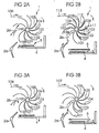
- FIGS. 2a and 2b a second embodiment of the spiral tray stacker is shown, which works in principle as well as the previously with respect to the FIGS. 1a to 1d described embodiment.
- FIG. 2a shows the stacker 1 at the same time as Figure 1c , The procedure is identical in this respect.
- an auxiliary stacking tray 6 is inserted between the stacker wheel 1 and the banknote stack 5, so that the spiral slot stacker is much faster ready for stacking a next sheet stack.
- the co-moving second part 2b of the stripper can be locked in the stripping position after one revolution of the stacker wheel 1 again.
- the stack tray 4 and the auxiliary stack tray 6 are formed like a comb.
- the stack tray 4 is lowered with the banknote stack 5, so that the auxiliary stacking unit 6 can be positioned over it.
- the banknote stack 5 After the banknote stack 5 has been removed from the stacking tray 4, it is raised to the level of the auxiliary stacking tray 6 with the banknotes 101, 109, 102, 110 etc. stacked thereon such that the tines of the two trays 4 and 6 mesh in a comb-like manner and form a common storage level.
- the auxiliary stacking tray 6 In order to avoid a collision of the auxiliary stacking tray 6 with the first part 2a of the stripper 2 moved out of the stacker wheel 1, the auxiliary stacking tray 6 is supplied, for example, in a direction parallel to the axis of rotation of the stacker wheel.
- FIG. 3a shows the spiral forklift in the same position as FIG. 2a ,
- the second part 2b of the stripper 2 is only moved along with the stacker wheel 1 until the hundredth banknote 100 has been stripped onto the stacking tray 4.
- the stack tray 4 is lowered, the auxiliary stack tray 6 positioned over the lowered stack tray 4 and the second part 2b of the stripper 2 is moved back against the direction of rotation of the stacker wheel 1 in the stripping position.
- FIG. 3b FIG. 2 shows the stacker wheel 1 with the second part 2b of the stripper 2 moved back into the stripping position and the intermediate stacking tray 6 inserted.
- the stripping of the first banknote 101 for the next banknote stack begins with the second part 2b of the stripper 2 moving back to the stripping position and is approximately then terminated when the auxiliary stacking tray 6 has reached its position for destacking the next batch of banknotes.
- the first part 2a of the stripper 2 can be retracted without risk of collision with the banknotes in the stacker wheel 1 into the stacker wheel 1.
- the stack tray 4 is raised in the manner described above to the level of the auxiliary stack tray 6, and this can be moved out of their comb-like engagement with the stack tray 4.
Landscapes
- Engineering & Computer Science (AREA)
- Mechanical Engineering (AREA)
- Pile Receivers (AREA)
- Discharge By Other Means (AREA)
Claims (8)
- Dispositif d'empilage en hélice pour l'empilage d'objets en forme de feuilles, comportant- une roue (1) avec des compartiments, qui sont agencés en forme d'hélice les uns derrière les autres autour d'un axe de rotation et sont destinés à recevoir l'objet en forme de feuille,- un éjecteur (2 ; 2a, 2b), qui comporte une première partie mobile (2) qui, dans une position d'éjection, éjecte l'objet en forme de feuille hors des compartiments de la roue, et- un collecteur (4) pour empiler l'objet en forme de feuille éjecté hors des compartiments,sachant que la première partie mobile (2) de l'éjecteur (2), pendant la rotation de la roue (1), peut être déplacée hors de la position d'éjection, de telle sorte que l'objet en forme de feuille (100) de l'un des compartiments est éjecté hors de la roue et l'objet en forme de feuille (100) d'un compartiment consécutif reste dans la roue, caractérisé en ce que
une deuxième partie mobile (2b) de l'éjecteur (2) peut être bloquée dans la position d'éjection et, dans la position non bloquée, peut être entraînée en rotation avec la roue (1) qui tourne. - Dispositif d'empilage en hélice selon la revendication 1, caractérisé par un collecteur auxiliaire (6), qui peut être déplacé au-dessus du collecteur (4) et peut être amené avec le collecteur (4) au même niveau.
- Dispositif d'empilage en hélice selon la revendication 2, caractérisé en ce que le collecteur auxiliaire (6) et le collecteur (4) peuvent s'engager l'un dans l'autre à la manière d'un engrènement.
- Dispositif d'empilage en hélice selon l'une quelconque des revendications 1 à 3, caractérisé en ce que la deuxième partie mobile (2b) de l'éjecteur (2) peut être ramenée dans la position d'éjection dans le sens opposé au sens de rotation de la roue (1).
- Dispositif de traitement de billets de banque, comportant un ou plusieurs dispositifs d'empilage en hélice selon l'une quelconque des revendications 1 à 4.
- Procédé pour l'empilage d'objets en forme de feuilles au moyen d'un dispositif d'empilage en hélice comportant une roue (1) qui est munie de compartiments, qui sont agencés en forme d'hélice les uns derrière les autres autour d'un axe de rotation et sont destinés à recevoir l'objet en forme de feuille (98 à 113), comportant les étapes suivantes :- admission de l'objet en forme de feuille dans les compartiments de la roue,- éjection de l'objet en forme de feuille hors des compartiments de la roue sur un collecteur (4) au moyen d'un éjecteur (2 ; 2a, 2b), disposé dans une position d'éjection, en vue de former une pile (5) d'objets en forme de feuilles,- lorsqu'un nombre prédéterminé de feuilles est empilé, déplacement d'une première partie mobile (2a) de l'éjecteur (2) hors de la position d'éjection pendant que la roue (1) tourne, de telle sorte que la dernière feuille (100) du nombre prédéterminé de feuilles est éjectée hors de la roue et la feuille (101) d'un compartiment consécutif reste dans la roue,- préparation du dispositif d'empilage en hélice pour l'empilage d'une prochaine pile d'objets en forme de feuilles, et- retour de la première partie mobile (2a) de l'éjecteur (2) dans la position d'éjection,caractérisé par les étapes suivantes :- déblocage d'une deuxième partie mobile (2b) de l'éjecteur (2) hors de la position d'éjection et entraînement en rotation de celle-ci avec la roue (1) qui tourne, lorsque la première partie (2a) de l'éjecteur (2) est déplacée hors de la position d'éjection,- admission supplémentaire de feuilles dans les compartiments de la roue, pendant que la deuxième partie (2b) de l'éjecteur (2) est entraînée en rotation avec la roue (1),- blocage de la deuxième partie (2b) de l'éjecteur (2) dans la position d'éjection, lorsque le dispositif d'empilage en hélice est prêt à empiler la pile suivante d'objets en forme de feuilles, et éjection de l'objet en forme de feuille contenu dans les compartiments au moyen de la deuxième partie (2b) de l'éjecteur (2) avant que la première partie (2a) de l'éjecteur (2) soit ramenée dans la position d'éjection.
- Procédé selon la revendication 6, dans lequel l'étape de la préparation du dispositif d'empilage en hélice pour l'empilage d'une pile suivante d'objets en forme de feuilles comporte les étapes suivantes :- acheminement d'un collecteur auxiliaire (6) au-dessus du collecteur (4) pour empiler temporairement sur celui-ci la pile suivante d'objets en forme de feuilles,- enlèvement de la pile de feuilles (5) posée sur le collecteur (4), et- déplacement du collecteur auxiliaire (6) sur lequel est empilée temporairement la pile de feuilles, et déplacement du collecteur (4) sur le même niveau une fois que la pile de feuilles (5) a été enlevée du collecteur (4).
- Procédé selon la revendication 6 ou 7, dans lequel la deuxième partie (2b) de l'éjecteur (2) est déplacée en retour dans le sens opposé au sens de rotation de la roue (1), pour la bloquer dans la position d'éjection.
Applications Claiming Priority (3)
| Application Number | Priority Date | Filing Date | Title |
|---|---|---|---|
| DE10234970 | 2002-07-31 | ||
| DE10234970A DE10234970B4 (de) | 2002-07-31 | 2002-07-31 | Verfahren und Vorrichtung zum Stapeln von Blattgut |
| PCT/EP2003/008434 WO2004013025A1 (fr) | 2002-07-31 | 2003-07-30 | Procede et dispositif pour empiler des objets sous forme de feuilles |
Publications (2)
| Publication Number | Publication Date |
|---|---|
| EP1527007A1 EP1527007A1 (fr) | 2005-05-04 |
| EP1527007B1 true EP1527007B1 (fr) | 2011-09-14 |
Family
ID=30128564
Family Applications (1)
| Application Number | Title | Priority Date | Filing Date |
|---|---|---|---|
| EP03766368A Expired - Lifetime EP1527007B1 (fr) | 2002-07-31 | 2003-07-30 | Procede et dispositif pour empiler des objets sous forme de feuilles |
Country Status (9)
| Country | Link |
|---|---|
| US (1) | US7318586B2 (fr) |
| EP (1) | EP1527007B1 (fr) |
| JP (1) | JP4390145B2 (fr) |
| CN (1) | CN100532229C (fr) |
| AT (1) | ATE524402T1 (fr) |
| AU (1) | AU2003255328A1 (fr) |
| DE (1) | DE10234970B4 (fr) |
| RU (1) | RU2317935C2 (fr) |
| WO (1) | WO2004013025A1 (fr) |
Families Citing this family (10)
| Publication number | Priority date | Publication date | Assignee | Title |
|---|---|---|---|---|
| DE102004016109A1 (de) * | 2004-04-01 | 2005-11-03 | Goss International Americas, Inc.(N.D.Ges.D. Staates Delaware) | Schaufelradauslage für einen Falzapparat |
| DE102004023312A1 (de) | 2004-05-11 | 2005-12-15 | Giesecke & Devrient Gmbh | Verfahren und Vorrichtung zum Stapeln von Blattgut |
| DE102004030143A1 (de) * | 2004-06-22 | 2006-01-19 | Giesecke & Devrient Gmbh | Vorrichtung und Verfahren zur Bearbeitung von Banknoten |
| ITBO20060289A1 (it) * | 2006-04-14 | 2007-10-15 | Tech S R L S | Dispositivo di impilamento per fazzoletti, tovaglioli e simili. |
| CN103562105B (zh) * | 2011-03-30 | 2015-12-16 | 光荣株式会社 | 叶轮、纸张积累装置以及叶轮的制造方法 |
| JP5983334B2 (ja) * | 2012-11-13 | 2016-08-31 | 沖電気工業株式会社 | 位置調整装置及び紙葉類処理装置 |
| JP2014179033A (ja) * | 2013-03-15 | 2014-09-25 | Toshiba Corp | 紙葉類処理装置 |
| US11084680B1 (en) | 2018-04-05 | 2021-08-10 | Imaging Business Machines Llc | Continually running pocket spindle |
| JP6778782B2 (ja) | 2019-04-18 | 2020-11-04 | 日本金銭機械株式会社 | 紙葉処理装置、集積トレイ、及び紙葉集積方法 |
| CN116169375B (zh) * | 2023-03-08 | 2026-04-14 | 海目星激光科技集团股份有限公司 | 一种叠片装置 |
Family Cites Families (22)
| Publication number | Priority date | Publication date | Assignee | Title |
|---|---|---|---|---|
| US3531108A (en) * | 1968-06-04 | 1970-09-29 | Control Data Corp | Document stacker and/or sorter |
| US3851773A (en) * | 1972-07-08 | 1974-12-03 | W Kluge | Stacking device, particularly for newspapers |
| SU431081A1 (ru) * | 1972-09-06 | 1974-06-05 | В. В. Макаров Слав нский керамический комбинат | Устройство для укладки стоп из плоских изделий |
| US4501418A (en) * | 1981-02-24 | 1985-02-26 | Tokyo Shibaura Denki Kabushiki Kaisha | Stacking device for paper sheets |
| JPS57138847U (fr) * | 1981-02-24 | 1982-08-30 | ||
| JPS58113067A (ja) | 1981-12-25 | 1983-07-05 | Toshiba Corp | 紙葉類の集積装置 |
| JPS5943762A (ja) * | 1982-09-03 | 1984-03-10 | Toshiba Corp | 紙葉類回収装置 |
| JPS59172354A (ja) * | 1983-03-16 | 1984-09-29 | Toshiba Corp | 紙葉類回収装置 |
| JPS59182156A (ja) * | 1983-03-31 | 1984-10-16 | Toshiba Corp | 紙葉類回収装置 |
| JPS59184989A (ja) * | 1983-04-04 | 1984-10-20 | 株式会社東芝 | 区分集積装置 |
| JPS59223650A (ja) * | 1983-05-31 | 1984-12-15 | Toshiba Corp | 紙葉類の集積装置 |
| US5104282A (en) * | 1991-03-11 | 1992-04-14 | Bell & Howell Phillipsburg Co. | Document feeder |
| US5359930A (en) * | 1993-09-17 | 1994-11-01 | Rockwell International Corporation | Device for aligning flies for a printing press |
| DE69421783T2 (de) * | 1993-09-20 | 2000-07-06 | Kabushiki Kaisha Toshiba, Kawasaki | Vorrichtung zur Kontrolle von bogenförmigen Materialien und Transportvorrichtung für diese |
| DE4437722A1 (de) * | 1994-10-21 | 1996-04-25 | Giesecke & Devrient Gmbh | Verfahren und Vorrichtung zur Verarbeitung von Banknoten |
| GB9510297D0 (en) * | 1995-05-22 | 1995-07-19 | De La Rue Systems Ltd | Improvements relating to sheet feeding |
| GB9515437D0 (en) * | 1995-07-27 | 1995-09-27 | Rue De Systems Ltd | Sheet feeding apparatus and method |
| DE19719239A1 (de) * | 1997-05-07 | 1998-11-12 | Giesecke & Devrient Gmbh | Vorrichtung zur automatischen Bündelung von Blattgut |
| US6131903A (en) * | 1999-07-20 | 2000-10-17 | Quad/Tech, Inc. | Signature stripping mechanism |
| ITBO20000475A1 (it) * | 2000-07-31 | 2002-01-31 | Cat System S R L | Dispositivo per la separazione di gruppi di foglietti in una apparecchiatura per la formazione e la fascettatura di gruppi di fogli , quali |
| US6877740B2 (en) * | 2003-07-30 | 2005-04-12 | C.G. Bretting Manufacturing Company, Inc. | Starwheel feed apparatus and method |
| JP2005335949A (ja) * | 2004-04-30 | 2005-12-08 | Komori Corp | 排紙装置 |
-
2002
- 2002-07-31 DE DE10234970A patent/DE10234970B4/de not_active Expired - Fee Related
-
2003
- 2003-07-30 US US10/523,248 patent/US7318586B2/en not_active Expired - Lifetime
- 2003-07-30 JP JP2004525385A patent/JP4390145B2/ja not_active Expired - Fee Related
- 2003-07-30 AU AU2003255328A patent/AU2003255328A1/en not_active Abandoned
- 2003-07-30 EP EP03766368A patent/EP1527007B1/fr not_active Expired - Lifetime
- 2003-07-30 AT AT03766368T patent/ATE524402T1/de active
- 2003-07-30 CN CNB038180251A patent/CN100532229C/zh not_active Expired - Fee Related
- 2003-07-30 RU RU2005105689/11A patent/RU2317935C2/ru not_active IP Right Cessation
- 2003-07-30 WO PCT/EP2003/008434 patent/WO2004013025A1/fr not_active Ceased
Also Published As
| Publication number | Publication date |
|---|---|
| US20050253322A1 (en) | 2005-11-17 |
| AU2003255328A1 (en) | 2004-02-23 |
| RU2317935C2 (ru) | 2008-02-27 |
| DE10234970A1 (de) | 2004-02-12 |
| RU2005105689A (ru) | 2006-04-10 |
| CN100532229C (zh) | 2009-08-26 |
| EP1527007A1 (fr) | 2005-05-04 |
| ATE524402T1 (de) | 2011-09-15 |
| US7318586B2 (en) | 2008-01-15 |
| WO2004013025A1 (fr) | 2004-02-12 |
| CN1671611A (zh) | 2005-09-21 |
| DE10234970B4 (de) | 2005-04-28 |
| JP2005535027A (ja) | 2005-11-17 |
| JP4390145B2 (ja) | 2009-12-24 |
Similar Documents
| Publication | Publication Date | Title |
|---|---|---|
| EP0708419B1 (fr) | Procédé et appareil pour le traitement des billets de banque | |
| DE3420336C2 (de) | Papierblatt-Ablagevorrichtung | |
| DE2502222C3 (de) | Vorrichtung zum Prüfen eines Banknotenbündels auf Vollzähligkeit | |
| DE2758007B1 (de) | Verfahren zum Steuern des Abzugsvorgangs bei einer Einrichtung zur Abgabe vereinzelter Sendungen von unterschiedlicher Laenge sowie entsprechende Einrichtung | |
| CH667621A5 (de) | Sammelhefter. | |
| DE3316740A1 (de) | Vorrichtung zum zusammentragen von zeitungen | |
| DE2553518A1 (de) | Blattwende- und ablegevorrichtung | |
| EP1527007B1 (fr) | Procede et dispositif pour empiler des objets sous forme de feuilles | |
| WO1995009796A1 (fr) | Procede et dispositif permettant de former et de deplacer des piles de feuilles imprimees | |
| EP2190763B1 (fr) | Dispositif de séparation d'objets en forme de feuilles | |
| DE3008897C2 (de) | Sortierer für von einem Kopiergerät oder einem Drucker zugeführte, einzelne Blätter | |
| EP0265735A1 (fr) | Procédure et dispositif pour enlever les produits imprimés et pliés des machines d'imprimerie | |
| DE2747799C2 (fr) | ||
| EP1747159B1 (fr) | Procede et dispositif pour empiler des elements se presentant sous la forme de feuilles | |
| DE60121654T2 (de) | Vorrichtung zum Zählen und Stapeln von flachen Produkten | |
| DE2651533A1 (de) | Schriftstueckableiteinrichtung | |
| EP1149791B1 (fr) | Dispositif pour prélever une feuille d'essai dans un appareil de sortie d'une machine à imprimer des feuilles | |
| EP0591099A1 (fr) | Procédé et dispositif pour fabriquer des piles de produits en papier liées | |
| DE19940405C2 (de) | Verfahren und Vorrichtung zum Ausgeben einer vorbestimmten Anzahl von Blättern aus einer Gruppe von Blättern | |
| EP0185395B1 (fr) | Dispositif de séparation de feuilles | |
| WO2005073116A1 (fr) | Dispositif pour empiler des objets souples plats | |
| EP1704107B1 (fr) | Empileuse a compartiments en spirale | |
| DE10140101B4 (de) | Blattgutstapelvorrichtung | |
| DE3839305A1 (de) | Vorrichtung zum stapelweisen ablegen von einzeln zugefuehrten blaettern | |
| DE9104607U1 (de) | Vorrichtung zum Sammeln und Falzen von Papierbogen |
Legal Events
| Date | Code | Title | Description |
|---|---|---|---|
| PUAI | Public reference made under article 153(3) epc to a published international application that has entered the european phase |
Free format text: ORIGINAL CODE: 0009012 |
|
| 17P | Request for examination filed |
Effective date: 20050228 |
|
| AK | Designated contracting states |
Kind code of ref document: A1 Designated state(s): AT BE BG CH CY CZ DE DK EE ES FI FR GB GR HU IE IT LI LU MC NL PT RO SE SI SK TR |
|
| AX | Request for extension of the european patent |
Extension state: AL LT LV MK |
|
| DAX | Request for extension of the european patent (deleted) | ||
| 17Q | First examination report despatched |
Effective date: 20080529 |
|
| GRAJ | Information related to disapproval of communication of intention to grant by the applicant or resumption of examination proceedings by the epo deleted |
Free format text: ORIGINAL CODE: EPIDOSDIGR1 |
|
| GRAP | Despatch of communication of intention to grant a patent |
Free format text: ORIGINAL CODE: EPIDOSNIGR1 |
|
| GRAS | Grant fee paid |
Free format text: ORIGINAL CODE: EPIDOSNIGR3 |
|
| GRAA | (expected) grant |
Free format text: ORIGINAL CODE: 0009210 |
|
| AK | Designated contracting states |
Kind code of ref document: B1 Designated state(s): AT BE BG CH CY CZ DE DK EE ES FI FR GB GR HU IE IT LI LU MC NL PT RO SE SI SK TR |
|
| REG | Reference to a national code |
Ref country code: GB Ref legal event code: FG4D Free format text: NOT ENGLISH |
|
| REG | Reference to a national code |
Ref country code: CH Ref legal event code: EP |
|
| REG | Reference to a national code |
Ref country code: IE Ref legal event code: FG4D Free format text: LANGUAGE OF EP DOCUMENT: GERMAN Ref country code: DE Ref legal event code: R081 Ref document number: 50313952 Country of ref document: DE Owner name: GIESECKE+DEVRIENT CURRENCY TECHNOLOGY GMBH, DE Free format text: FORMER OWNER: GIESECKE & DEVRIENT GMBH, 81677 MUENCHEN, DE |
|
| REG | Reference to a national code |
Ref country code: DE Ref legal event code: R096 Ref document number: 50313952 Country of ref document: DE Effective date: 20111201 |
|
| REG | Reference to a national code |
Ref country code: NL Ref legal event code: VDEP Effective date: 20110914 |
|
| PG25 | Lapsed in a contracting state [announced via postgrant information from national office to epo] |
Ref country code: FI Free format text: LAPSE BECAUSE OF FAILURE TO SUBMIT A TRANSLATION OF THE DESCRIPTION OR TO PAY THE FEE WITHIN THE PRESCRIBED TIME-LIMIT Effective date: 20110914 Ref country code: SE Free format text: LAPSE BECAUSE OF FAILURE TO SUBMIT A TRANSLATION OF THE DESCRIPTION OR TO PAY THE FEE WITHIN THE PRESCRIBED TIME-LIMIT Effective date: 20110914 |
|
| PG25 | Lapsed in a contracting state [announced via postgrant information from national office to epo] |
Ref country code: CY Free format text: LAPSE BECAUSE OF FAILURE TO SUBMIT A TRANSLATION OF THE DESCRIPTION OR TO PAY THE FEE WITHIN THE PRESCRIBED TIME-LIMIT Effective date: 20110914 Ref country code: SI Free format text: LAPSE BECAUSE OF FAILURE TO SUBMIT A TRANSLATION OF THE DESCRIPTION OR TO PAY THE FEE WITHIN THE PRESCRIBED TIME-LIMIT Effective date: 20110914 Ref country code: GR Free format text: LAPSE BECAUSE OF FAILURE TO SUBMIT A TRANSLATION OF THE DESCRIPTION OR TO PAY THE FEE WITHIN THE PRESCRIBED TIME-LIMIT Effective date: 20111215 |
|
| REG | Reference to a national code |
Ref country code: IE Ref legal event code: FD4D |
|
| PG25 | Lapsed in a contracting state [announced via postgrant information from national office to epo] |
Ref country code: IE Free format text: LAPSE BECAUSE OF FAILURE TO SUBMIT A TRANSLATION OF THE DESCRIPTION OR TO PAY THE FEE WITHIN THE PRESCRIBED TIME-LIMIT Effective date: 20110914 Ref country code: CZ Free format text: LAPSE BECAUSE OF FAILURE TO SUBMIT A TRANSLATION OF THE DESCRIPTION OR TO PAY THE FEE WITHIN THE PRESCRIBED TIME-LIMIT Effective date: 20110914 Ref country code: SK Free format text: LAPSE BECAUSE OF FAILURE TO SUBMIT A TRANSLATION OF THE DESCRIPTION OR TO PAY THE FEE WITHIN THE PRESCRIBED TIME-LIMIT Effective date: 20110914 |
|
| PG25 | Lapsed in a contracting state [announced via postgrant information from national office to epo] |
Ref country code: NL Free format text: LAPSE BECAUSE OF FAILURE TO SUBMIT A TRANSLATION OF THE DESCRIPTION OR TO PAY THE FEE WITHIN THE PRESCRIBED TIME-LIMIT Effective date: 20110914 Ref country code: PT Free format text: LAPSE BECAUSE OF FAILURE TO SUBMIT A TRANSLATION OF THE DESCRIPTION OR TO PAY THE FEE WITHIN THE PRESCRIBED TIME-LIMIT Effective date: 20120116 Ref country code: RO Free format text: LAPSE BECAUSE OF FAILURE TO SUBMIT A TRANSLATION OF THE DESCRIPTION OR TO PAY THE FEE WITHIN THE PRESCRIBED TIME-LIMIT Effective date: 20110914 Ref country code: EE Free format text: LAPSE BECAUSE OF FAILURE TO SUBMIT A TRANSLATION OF THE DESCRIPTION OR TO PAY THE FEE WITHIN THE PRESCRIBED TIME-LIMIT Effective date: 20110914 |
|
| PLBE | No opposition filed within time limit |
Free format text: ORIGINAL CODE: 0009261 |
|
| STAA | Information on the status of an ep patent application or granted ep patent |
Free format text: STATUS: NO OPPOSITION FILED WITHIN TIME LIMIT |
|
| PG25 | Lapsed in a contracting state [announced via postgrant information from national office to epo] |
Ref country code: DK Free format text: LAPSE BECAUSE OF FAILURE TO SUBMIT A TRANSLATION OF THE DESCRIPTION OR TO PAY THE FEE WITHIN THE PRESCRIBED TIME-LIMIT Effective date: 20110914 |
|
| 26N | No opposition filed |
Effective date: 20120615 |
|
| REG | Reference to a national code |
Ref country code: DE Ref legal event code: R097 Ref document number: 50313952 Country of ref document: DE Effective date: 20120615 |
|
| BERE | Be: lapsed |
Owner name: GIESECKE & DEVRIENT G.M.B.H. Effective date: 20120731 |
|
| PG25 | Lapsed in a contracting state [announced via postgrant information from national office to epo] |
Ref country code: MC Free format text: LAPSE BECAUSE OF NON-PAYMENT OF DUE FEES Effective date: 20120731 |
|
| REG | Reference to a national code |
Ref country code: CH Ref legal event code: PL |
|
| PG25 | Lapsed in a contracting state [announced via postgrant information from national office to epo] |
Ref country code: LI Free format text: LAPSE BECAUSE OF NON-PAYMENT OF DUE FEES Effective date: 20120731 Ref country code: ES Free format text: LAPSE BECAUSE OF FAILURE TO SUBMIT A TRANSLATION OF THE DESCRIPTION OR TO PAY THE FEE WITHIN THE PRESCRIBED TIME-LIMIT Effective date: 20111225 Ref country code: CH Free format text: LAPSE BECAUSE OF NON-PAYMENT OF DUE FEES Effective date: 20120731 |
|
| PG25 | Lapsed in a contracting state [announced via postgrant information from national office to epo] |
Ref country code: BE Free format text: LAPSE BECAUSE OF NON-PAYMENT OF DUE FEES Effective date: 20120731 |
|
| PG25 | Lapsed in a contracting state [announced via postgrant information from national office to epo] |
Ref country code: BG Free format text: LAPSE BECAUSE OF FAILURE TO SUBMIT A TRANSLATION OF THE DESCRIPTION OR TO PAY THE FEE WITHIN THE PRESCRIBED TIME-LIMIT Effective date: 20111214 |
|
| REG | Reference to a national code |
Ref country code: AT Ref legal event code: MM01 Ref document number: 524402 Country of ref document: AT Kind code of ref document: T Effective date: 20120731 |
|
| PG25 | Lapsed in a contracting state [announced via postgrant information from national office to epo] |
Ref country code: AT Free format text: LAPSE BECAUSE OF NON-PAYMENT OF DUE FEES Effective date: 20120731 |
|
| PG25 | Lapsed in a contracting state [announced via postgrant information from national office to epo] |
Ref country code: TR Free format text: LAPSE BECAUSE OF FAILURE TO SUBMIT A TRANSLATION OF THE DESCRIPTION OR TO PAY THE FEE WITHIN THE PRESCRIBED TIME-LIMIT Effective date: 20110914 |
|
| PG25 | Lapsed in a contracting state [announced via postgrant information from national office to epo] |
Ref country code: LU Free format text: LAPSE BECAUSE OF NON-PAYMENT OF DUE FEES Effective date: 20120730 |
|
| PG25 | Lapsed in a contracting state [announced via postgrant information from national office to epo] |
Ref country code: HU Free format text: LAPSE BECAUSE OF FAILURE TO SUBMIT A TRANSLATION OF THE DESCRIPTION OR TO PAY THE FEE WITHIN THE PRESCRIBED TIME-LIMIT Effective date: 20030730 |
|
| PGFP | Annual fee paid to national office [announced via postgrant information from national office to epo] |
Ref country code: IT Payment date: 20140728 Year of fee payment: 12 |
|
| REG | Reference to a national code |
Ref country code: FR Ref legal event code: PLFP Year of fee payment: 13 |
|
| PGFP | Annual fee paid to national office [announced via postgrant information from national office to epo] |
Ref country code: FR Payment date: 20150730 Year of fee payment: 13 |
|
| PG25 | Lapsed in a contracting state [announced via postgrant information from national office to epo] |
Ref country code: IT Free format text: LAPSE BECAUSE OF NON-PAYMENT OF DUE FEES Effective date: 20150730 |
|
| REG | Reference to a national code |
Ref country code: DE Ref legal event code: R084 Ref document number: 50313952 Country of ref document: DE |
|
| PG25 | Lapsed in a contracting state [announced via postgrant information from national office to epo] |
Ref country code: FR Free format text: LAPSE BECAUSE OF NON-PAYMENT OF DUE FEES Effective date: 20160801 |
|
| REG | Reference to a national code |
Ref country code: FR Ref legal event code: ST Effective date: 20170331 |
|
| REG | Reference to a national code |
Ref country code: DE Ref legal event code: R081 Ref document number: 50313952 Country of ref document: DE Owner name: GIESECKE+DEVRIENT CURRENCY TECHNOLOGY GMBH, DE Free format text: FORMER OWNER: GIESECKE & DEVRIENT GMBH, 81677 MUENCHEN, DE |
|
| REG | Reference to a national code |
Ref country code: GB Ref legal event code: 732E Free format text: REGISTERED BETWEEN 20180118 AND 20180124 |
|
| PGFP | Annual fee paid to national office [announced via postgrant information from national office to epo] |
Ref country code: DE Payment date: 20190731 Year of fee payment: 17 |
|
| PGFP | Annual fee paid to national office [announced via postgrant information from national office to epo] |
Ref country code: GB Payment date: 20190725 Year of fee payment: 17 |
|
| REG | Reference to a national code |
Ref country code: DE Ref legal event code: R119 Ref document number: 50313952 Country of ref document: DE |
|
| GBPC | Gb: european patent ceased through non-payment of renewal fee |
Effective date: 20200730 |
|
| PG25 | Lapsed in a contracting state [announced via postgrant information from national office to epo] |
Ref country code: GB Free format text: LAPSE BECAUSE OF NON-PAYMENT OF DUE FEES Effective date: 20200730 |
|
| PG25 | Lapsed in a contracting state [announced via postgrant information from national office to epo] |
Ref country code: DE Free format text: LAPSE BECAUSE OF NON-PAYMENT OF DUE FEES Effective date: 20210202 |