EP1527824A2 - Amélioration pour cabines de pulverisation et stations de séchage - Google Patents
Amélioration pour cabines de pulverisation et stations de séchage Download PDFInfo
- Publication number
- EP1527824A2 EP1527824A2 EP04025413A EP04025413A EP1527824A2 EP 1527824 A2 EP1527824 A2 EP 1527824A2 EP 04025413 A EP04025413 A EP 04025413A EP 04025413 A EP04025413 A EP 04025413A EP 1527824 A2 EP1527824 A2 EP 1527824A2
- Authority
- EP
- European Patent Office
- Prior art keywords
- air
- space
- panels
- spray booth
- preparation station
- Prior art date
- Legal status (The legal status is an assumption and is not a legal conclusion. Google has not performed a legal analysis and makes no representation as to the accuracy of the status listed.)
- Ceased
Links
Images


Classifications
-
- F—MECHANICAL ENGINEERING; LIGHTING; HEATING; WEAPONS; BLASTING
- F26—DRYING
- F26B—DRYING SOLID MATERIALS OR OBJECTS BY REMOVING LIQUID THEREFROM
- F26B3/00—Drying solid materials or objects by processes involving the application of heat
- F26B3/28—Drying solid materials or objects by processes involving the application of heat by radiation, e.g. from the sun
- F26B3/30—Drying solid materials or objects by processes involving the application of heat by radiation, e.g. from the sun from infrared-emitting elements
- F26B3/305—Drying solid materials or objects by processes involving the application of heat by radiation, e.g. from the sun from infrared-emitting elements the infrared radiation being generated by combustion or combustion gases
-
- B—PERFORMING OPERATIONS; TRANSPORTING
- B05—SPRAYING OR ATOMISING IN GENERAL; APPLYING FLUENT MATERIALS TO SURFACES, IN GENERAL
- B05B—SPRAYING APPARATUS; ATOMISING APPARATUS; NOZZLES
- B05B14/00—Arrangements for collecting, re-using or eliminating excess spraying material
- B05B14/40—Arrangements for collecting, re-using or eliminating excess spraying material for use in spray booths
- B05B14/41—Arrangements for collecting, re-using or eliminating excess spraying material for use in spray booths by cleaning the walls of the booth
- B05B14/412—Arrangements for collecting, re-using or eliminating excess spraying material for use in spray booths by cleaning the walls of the booth wherein the walls of the booth is perforated or porous walls and the walls are cleaned of or prevented from being contacted with excess material by a flow of fluid, e.g. air or water, directed into the booth
-
- B—PERFORMING OPERATIONS; TRANSPORTING
- B05—SPRAYING OR ATOMISING IN GENERAL; APPLYING FLUENT MATERIALS TO SURFACES, IN GENERAL
- B05B—SPRAYING APPARATUS; ATOMISING APPARATUS; NOZZLES
- B05B16/00—Spray booths
- B05B16/40—Construction elements specially adapted therefor, e.g. floors, walls or ceilings
-
- F—MECHANICAL ENGINEERING; LIGHTING; HEATING; WEAPONS; BLASTING
- F26—DRYING
- F26B—DRYING SOLID MATERIALS OR OBJECTS BY REMOVING LIQUID THEREFROM
- F26B21/00—Arrangements for supplying or controlling air or other gases for drying solid materials or objects
- F26B21/001—Air generating units, e.g. movable or independent of drying enclosure
- F26B21/002—Air generating units, e.g. movable or independent of drying enclosure with means for indirect air heating, i.e. using heat exchangers
-
- F—MECHANICAL ENGINEERING; LIGHTING; HEATING; WEAPONS; BLASTING
- F26—DRYING
- F26B—DRYING SOLID MATERIALS OR OBJECTS BY REMOVING LIQUID THEREFROM
- F26B21/00—Arrangements for supplying or controlling air or other gases for drying solid materials or objects
- F26B21/003—Air or gas filters
-
- F—MECHANICAL ENGINEERING; LIGHTING; HEATING; WEAPONS; BLASTING
- F26—DRYING
- F26B—DRYING SOLID MATERIALS OR OBJECTS BY REMOVING LIQUID THEREFROM
- F26B21/00—Arrangements for supplying or controlling air or other gases for drying solid materials or objects
- F26B21/50—Ducting arrangements from the source of air or other gases to the materials or objects being dried
-
- F—MECHANICAL ENGINEERING; LIGHTING; HEATING; WEAPONS; BLASTING
- F26—DRYING
- F26B—DRYING SOLID MATERIALS OR OBJECTS BY REMOVING LIQUID THEREFROM
- F26B2210/00—Drying processes and machines for solid objects characterised by the specific requirements of the drying goods
- F26B2210/12—Vehicle bodies, e.g. after being painted
Definitions
- the present invention refers to the so called section relating to spray booths or and preparation stations.
- the spray booth structure consists of a principle space where an operator can feasibly carry out a painting operation for example, but not only, on parts of a vehicle. In the inside of the space in the booth warm air is introduced to dry the paint. Although it can be employed in the paint sector and for the drying one for parts of vehicles or in the industry connected with the spray booth it can also be employed in the drying of cereal, plastics, materials etc.
- the spray booth is an area where the operator or the robot paints, normally by spraying, the objects contained within, for example parts of vehicles.
- the present invention is to do with the improving of a spray booth and or a preparation station as indicated above.
- a spray booth which is destined to the drying of parts inside of it is composed of the following , as shown in figure 1:
- the normal system for the heating of the air introduced into the spray booth is based on a boiler with a combustion burner which heats the air before being released.
- a heating system for the air with a boiler and burner calls for an enormous space and an enormous consumption of energy.
- modifications have to be made and relevant permission has to be had.
- it is necessary to build walls to incorporate the heating apparatus thus reducing the space in the principal space for the spray booth.
- the goal of the actual invention is to solve the above problems.
- the goal is to diminish considerably the power ensuring the efficiency of the spray booth, and finally to simplify the installation and the running of the heating plant, eliminating the necessity for any administrative work and reducing the energy consumed in the using of the spray booth, increasing the space in the principal space of the spray booth.
- the goal is to make the cleaning of the booth more economic.
- the goal is to have a spray booth and or a working station working more efficiently both economically and technically in a notable way.
- the object of the invention is a spray booth and preparation station having the characteristics indicated in the claims paragraph.
- the invention With regard to the first aspect of the invention there are in the upper space in the spray booth ( as of now referred to as ceiling ) a series of panels radiating infrareds orientated towards the filters called plenum in such a way as to put heat in to fill the upper space concentrating the radiation on the filters called plenum. Instead of using the radiant panels the invention takes into account catalectic ones.
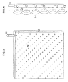
- a part of the walls of the spray booth and or the preparation station are constructed in panels hermetically sandwiched together, where the superficial of the panels turned towards the spray booth have a series of openings with a small distance between them, from which exits air which becomes fed into the sandwiched panels through a feeding tube.
- the air which exits at a certain pressure through the small openings creates a turbulence which distances the kind of fog from the spray away from the inside walls of the spray booth.
- a spray booth or preparation station where the objects which are to be painted or dried are placed, and which is normally accessible by the operator and is suited to the various operational movements of the objects and or the painting.
- an upper space 2 used as a pipe for the input of the air coming from the heating system directly from the main space 5.
- the upper space 2 is connected with the main space 5 with interposition of a layer of filters 4, called plenum, which have the function of filtering air, coming from the upper space 2 and directly towards the main space 5.
- the lower space 6 Under the main space 5 is situated the lower space 6, connected with the main space 5 with the interposition of a grilled floor or another similar system.
- the lower space 6 acts for the extraction of air after it has passed through the main space 5.
- a group of ventilators 7 for the extraction of air are situated at the end of the lower space 6 of a type generally known, while the emission group 8 are situated before of the upper space 2, and also they are also known in this field.
- the reference number 1 indicates the position of one or more radiation lamps or panels of infrareds, positioned in correspondence to the upper space or to the ceiling of the upper space 2 of the spray booth and are orientated in such a way that they guide the radiated energy towards the filters 4.
- the lamps or panels 1 radiant catalytic.
- the air destined to dry the objects placed in the main space 5 comes from the upper space 2 thanks to the group of emission ventilators 8, while the radiant panels 1 are activated in such away as to put heat into the whole of the upper space 2, and therefore the air which it comes into contact with, and in particular concentrating the radiation on to the filters 4, as shown in the schematic illustration in the figure 2 with the arrow 3.
- the emission group 8 in the upper space 2 happens the first transfer of energy released from the radiant panels 1 of the air.
- the moment in which the air, already partially heated, passes through the filter 4 there happens a total exchange of heat.
- the air becomes heated at the moment when it passes through the filters 4, heated by radiation from the panels or the radiant panels 1.
- At least a part of the walls of the spray booth and or the preparation station are covered with panels in sandwich form, consisting of two sheets with a parallel distance opposite each other, forming a room 13, preferably water tight or air tight, having internally in the space a tube 11 for feeding air.
- a room 13 preferably water tight or air tight
Landscapes
- Engineering & Computer Science (AREA)
- Mechanical Engineering (AREA)
- General Engineering & Computer Science (AREA)
- Chemical & Material Sciences (AREA)
- Combustion & Propulsion (AREA)
- Life Sciences & Earth Sciences (AREA)
- Microbiology (AREA)
- Details Or Accessories Of Spraying Plant Or Apparatus (AREA)
Applications Claiming Priority (2)
| Application Number | Priority Date | Filing Date | Title |
|---|---|---|---|
| IT000637A ITBO20030637A1 (it) | 2003-10-28 | 2003-10-28 | Cabina forno di verniciatura con sistema di riscaldamento |
| ITBO20030637 | 2003-10-28 |
Publications (2)
| Publication Number | Publication Date |
|---|---|
| EP1527824A2 true EP1527824A2 (fr) | 2005-05-04 |
| EP1527824A3 EP1527824A3 (fr) | 2009-07-29 |
Family
ID=34401299
Family Applications (1)
| Application Number | Title | Priority Date | Filing Date |
|---|---|---|---|
| EP04025413A Ceased EP1527824A3 (fr) | 2003-10-28 | 2004-10-26 | Amélioration pour cabines de pulverisation et stations de séchage |
Country Status (2)
| Country | Link |
|---|---|
| EP (1) | EP1527824A3 (fr) |
| IT (1) | ITBO20030637A1 (fr) |
Cited By (2)
| Publication number | Priority date | Publication date | Assignee | Title |
|---|---|---|---|---|
| CN111111991A (zh) * | 2020-01-14 | 2020-05-08 | 南京林业大学 | 一种金属展示架加工用喷涂装置 |
| CN114425547A (zh) * | 2022-04-07 | 2022-05-03 | 天津市英格环保科技有限公司 | 一种吸附催化式废气处理系统及方法 |
Citations (2)
| Publication number | Priority date | Publication date | Assignee | Title |
|---|---|---|---|---|
| US5473844A (en) | 1993-08-05 | 1995-12-12 | Omia | Cell for repairing vehicle bodywork |
| US6431857B1 (en) | 1999-03-25 | 2002-08-13 | Sunkiss | Catalytic combustion device emitting infrared radiation |
Family Cites Families (3)
| Publication number | Priority date | Publication date | Assignee | Title |
|---|---|---|---|---|
| GB1588503A (en) * | 1978-01-05 | 1981-04-23 | Toff J D | Installation and method for electrostatic powder coating of articles |
| US4787330A (en) * | 1987-12-22 | 1988-11-29 | Bolf Carl R | Self-cleaning powder coating booth |
| WO1997014508A1 (fr) * | 1995-10-18 | 1997-04-24 | Michael Eder | Dispositif pour le transport de substances finement reparties se formant lors du traitement de surface d'articles |
-
2003
- 2003-10-28 IT IT000637A patent/ITBO20030637A1/it unknown
-
2004
- 2004-10-26 EP EP04025413A patent/EP1527824A3/fr not_active Ceased
Patent Citations (2)
| Publication number | Priority date | Publication date | Assignee | Title |
|---|---|---|---|---|
| US5473844A (en) | 1993-08-05 | 1995-12-12 | Omia | Cell for repairing vehicle bodywork |
| US6431857B1 (en) | 1999-03-25 | 2002-08-13 | Sunkiss | Catalytic combustion device emitting infrared radiation |
Cited By (3)
| Publication number | Priority date | Publication date | Assignee | Title |
|---|---|---|---|---|
| CN111111991A (zh) * | 2020-01-14 | 2020-05-08 | 南京林业大学 | 一种金属展示架加工用喷涂装置 |
| CN111111991B (zh) * | 2020-01-14 | 2023-08-15 | 南京林业大学 | 一种金属展示架加工用喷涂装置 |
| CN114425547A (zh) * | 2022-04-07 | 2022-05-03 | 天津市英格环保科技有限公司 | 一种吸附催化式废气处理系统及方法 |
Also Published As
| Publication number | Publication date |
|---|---|
| EP1527824A3 (fr) | 2009-07-29 |
| ITBO20030637A1 (it) | 2005-04-29 |
Similar Documents
| Publication | Publication Date | Title |
|---|---|---|
| US9513057B2 (en) | Radiant convection oven | |
| US6062850A (en) | Paint curing oven | |
| US4785552A (en) | Convection stabilized radiant oven | |
| US5661912A (en) | Drier for a painting plant | |
| US7677243B2 (en) | Solar heating system and architectural structure with a solar heating system | |
| US5230161A (en) | Apparatus and process for generating radiant energy | |
| US4635381A (en) | Paint bake oven | |
| KR101320087B1 (ko) | 건조성능을 향상시킨 다목적 도장부스 | |
| US6533654B2 (en) | Integrated air flow booth and methods | |
| US7014338B2 (en) | Spray booth | |
| CN101934266A (zh) | 横向烘箱和烘烤工件的方法 | |
| CN113304937B (zh) | 一种机器人全自动喷涂生产线 | |
| US4136463A (en) | Radiant heat paint spray chamber | |
| EP2029950A1 (fr) | Four à combustion par convection | |
| JP2525652B2 (ja) | 塗装品乾燥炉 | |
| JP3112582B2 (ja) | 自動車塗装ブース並びに乾燥ブース | |
| CA2005416C (fr) | Appareil et methode de production d'energie rayonnante | |
| KR100542337B1 (ko) | 할로겐히터 도장 건조장치 | |
| CN102589077A (zh) | 送排风加热一体装置 | |
| KR100619427B1 (ko) | 루비코트 근적외선히터를 이용한 도장건조장치 | |
| KR100574832B1 (ko) | 원적외선 방사기능을 갖는 열풍식 농작물 건조장치 | |
| WO2006112600A1 (fr) | Dispositif de sechage de peinture faisant appel a un appareil de chauffage halogene | |
| KR100579509B1 (ko) | 원적외선 방사기능을 갖는 열풍식 농작물 건조장치의 채반 | |
| CA2639830C (fr) | Four a chauffage par rayonnement | |
| EP1527824A3 (fr) | Amélioration pour cabines de pulverisation et stations de séchage |
Legal Events
| Date | Code | Title | Description |
|---|---|---|---|
| PUAI | Public reference made under article 153(3) epc to a published international application that has entered the european phase |
Free format text: ORIGINAL CODE: 0009012 |
|
| AK | Designated contracting states |
Kind code of ref document: A2 Designated state(s): AT BE BG CH CY CZ DE DK EE ES FI FR GB GR HU IE IT LI LU MC NL PL PT RO SE SI SK TR |
|
| AX | Request for extension of the european patent |
Extension state: AL HR LT LV MK |
|
| RAP1 | Party data changed (applicant data changed or rights of an application transferred) |
Owner name: SYMACH S.R.L. |
|
| RIC1 | Information provided on ipc code assigned before grant |
Ipc: F23D 14/18 20060101ALI20090219BHEP Ipc: F26B 23/02 20060101ALI20090219BHEP Ipc: B05B 15/12 20060101AFI20050217BHEP |
|
| PUAL | Search report despatched |
Free format text: ORIGINAL CODE: 0009013 |
|
| AK | Designated contracting states |
Kind code of ref document: A3 Designated state(s): AT BE BG CH CY CZ DE DK EE ES FI FR GB GR HU IE IT LI LU MC NL PL PT RO SE SI SK TR |
|
| AX | Request for extension of the european patent |
Extension state: AL HR LT LV MK |
|
| 17P | Request for examination filed |
Effective date: 20100125 |
|
| AKX | Designation fees paid |
Designated state(s): DE FR GB IT |
|
| 17Q | First examination report despatched |
Effective date: 20100712 |
|
| STAA | Information on the status of an ep patent application or granted ep patent |
Free format text: STATUS: THE APPLICATION HAS BEEN REFUSED |
|
| 18R | Application refused |
Effective date: 20120930 |