EP1528036A2 - Zapfhahn für Getränke - Google Patents
Zapfhahn für Getränke Download PDFInfo
- Publication number
- EP1528036A2 EP1528036A2 EP04256724A EP04256724A EP1528036A2 EP 1528036 A2 EP1528036 A2 EP 1528036A2 EP 04256724 A EP04256724 A EP 04256724A EP 04256724 A EP04256724 A EP 04256724A EP 1528036 A2 EP1528036 A2 EP 1528036A2
- Authority
- EP
- European Patent Office
- Prior art keywords
- valve
- handle
- tap
- open
- dispense
- Prior art date
- Legal status (The legal status is an assumption and is not a legal conclusion. Google has not performed a legal analysis and makes no representation as to the accuracy of the status listed.)
- Withdrawn
Links
Images


Classifications
-
- B—PERFORMING OPERATIONS; TRANSPORTING
- B67—OPENING, CLOSING OR CLEANING BOTTLES, JARS OR SIMILAR CONTAINERS; LIQUID HANDLING
- B67D—DISPENSING, DELIVERING OR TRANSFERRING LIQUIDS, NOT OTHERWISE PROVIDED FOR
- B67D1/00—Apparatus or devices for dispensing beverages on draught
- B67D1/08—Details
- B67D1/12—Flow or pressure control devices or systems, e.g. valves, gas pressure control, level control in storage containers
- B67D1/1256—Anti-dripping devices
-
- B—PERFORMING OPERATIONS; TRANSPORTING
- B67—OPENING, CLOSING OR CLEANING BOTTLES, JARS OR SIMILAR CONTAINERS; LIQUID HANDLING
- B67D—DISPENSING, DELIVERING OR TRANSFERRING LIQUIDS, NOT OTHERWISE PROVIDED FOR
- B67D1/00—Apparatus or devices for dispensing beverages on draught
- B67D1/08—Details
- B67D1/12—Flow or pressure control devices or systems, e.g. valves, gas pressure control, level control in storage containers
- B67D1/14—Reducing valves or control taps
- B67D1/1405—Control taps
-
- B—PERFORMING OPERATIONS; TRANSPORTING
- B67—OPENING, CLOSING OR CLEANING BOTTLES, JARS OR SIMILAR CONTAINERS; LIQUID HANDLING
- B67D—DISPENSING, DELIVERING OR TRANSFERRING LIQUIDS, NOT OTHERWISE PROVIDED FOR
- B67D1/00—Apparatus or devices for dispensing beverages on draught
- B67D1/08—Details
- B67D1/12—Flow or pressure control devices or systems, e.g. valves, gas pressure control, level control in storage containers
- B67D1/14—Reducing valves or control taps
- B67D1/1405—Control taps
- B67D1/145—Control taps comprising a valve shutter movable in a direction perpendicular to the valve seat
- B67D1/1466—Control taps comprising a valve shutter movable in a direction perpendicular to the valve seat the valve shutter being opened in a direction opposite to the liquid flow
-
- B—PERFORMING OPERATIONS; TRANSPORTING
- B67—OPENING, CLOSING OR CLEANING BOTTLES, JARS OR SIMILAR CONTAINERS; LIQUID HANDLING
- B67D—DISPENSING, DELIVERING OR TRANSFERRING LIQUIDS, NOT OTHERWISE PROVIDED FOR
- B67D1/00—Apparatus or devices for dispensing beverages on draught
- B67D1/08—Details
- B67D1/12—Flow or pressure control devices or systems, e.g. valves, gas pressure control, level control in storage containers
- B67D1/14—Reducing valves or control taps
- B67D2001/1494—Taps with means for adjusting the position of a compensator from outside
Definitions
- This invention concerns improvements in or relating to beverage dispense. More especially, the invention relates to taps for dispensing a beverage and in particular, but not exclusively, to taps for dispensing beverages containing dissolved gas commonly referred to as carbonated beverages.
- Beverage dispense taps typically employ a tap body having an inlet connectable to a source of beverage, an outlet for dispensing the beverage into a receptacle, usually a glass, and a valve between the inlet and outlet that is manually operable via a handle to control dispense of the beverage.
- the tap may be provided with a compensator upstream of the valve to regulate the flow and maintain pressure in the supply line to prevent excessive, uncontrolled foaming of the beverage occurring in the dispense tap.
- the handle is connected to the valve in such a way that the handle is exposed to the flow of fluid through the tap when the valve is opened and which requires the handle to be detached from the tap body in order that the valve can be removed from the tap body for cleaning.
- Some taps are designed to be self-closing if the handle is released when the valve is open.
- a spring is usually provided that biases the valve towards the closed position.
- Such spring acts indirectly on the handle through the valve and may be exposed to the fluid flow through the tap so as to require cleaning. This adds to the complexity of the design.
- these normally include a control member that is axially adjustable to vary the size of an annular clearance gap.
- the control member is often coupled to a lever arranged externally of the tap body. Such lever is readily accessible and can result in the set position of the control member being altered by bar staff which may have an adverse effect on the dispense.
- the present invention has been made from a consideration of the foregoing problems and disadvantages of existing dispense taps.
- the present invention preferably seeks to provide a dispense tap that is self-closing in a reliable manner.
- the present invention optionally aims to provide a dispense tap with a compensator that is resistant to accidental or unauthorised adjustment of the set position.
- a dispense tap having an inlet for connection to a source of beverage, an outlet for dispensing a beverage, a valve between the inlet and outlet for controlling dispense of beverage, and a handle for actuating the valve, the handle being movable to a position in which the handle is uncoupled from the valve.
- the valve can be inserted in and removed from the tap with the handle in situ. As a result, removal of the valve for cleaning is facilitated.
- the tap has a tap body provided with the inlet and outlet and the valve is located within the tap body in a flow path between the inlet and outlet.
- the valve comprises a valve member operatively connected to the handle and movable relative to a valve seat in response to actuation of the handle to open and close the valve.
- the handle is movable from a first position in which the valve is closed to a second position to open the valve, and the handle is uncoupled from the valve member in the second position to permit removal of the valve member from the tap body.
- the handle is mounted for pivotal movement and has a drive formation for transmitting movement of the handle to the valve member.
- valve member has a piston slidable in a bore
- drive formation on the handle is co-operable with the piston in response to pivotal movement of the handle for displacing the piston to open and close the valve
- the bore is aligned with the inlet whereby the valve member can be withdrawn from the tap body through the inlet when the handle is in the second position.
- valve member is spring loaded to permit pivotal movement of the handle from the first position to a third position in a direction away from the second position to open a restricted flow passage that causes the beverage to foam and assist forming a head on the dispensed beverage.
- the handle has a stop formation co-operable with the tap body in each of the second and third positions.
- the handle is biased towards the first position so that the tap is self-closing if the handle is released when the valve is open.
- the resilient biasing is provided by a spring acting between the handle and the tap body.
- a spring acting between the handle and the tap body for example a torsion spring.
- the tap is provided with a compensator upstream of the valve.
- the compensator may comprise a control member axially movable to vary the size of an annular flow path around the control member.
- control member is adjustable externally of the tap body to permit the flow path setting to be altered without dis-assembly of the tap.
- control member is operatively connected to a rotatable drive shaft projecting from the tap body for actuation of the control member.
- the drive shaft is retained by a lock nut and has an outer end connected to an over-cap for rotating the drive shaft to adjust the set position of the control member.
- the lock nut may be operable to prevent rotation of the drive shaft to adjust the set position of the control member and the over-cap may conceal the lock nut. In this way, the setting of the control member can be fixed and accidental or unauthorised adjustment of the control member is inhibited.
- the tap body includes an air vent for introducing air to the flow path downstream of the valve.
- the air vent is preferably closed when the valve is open and is opened when the valve is closed. In this way, air is introduced to assist draining the tap when the valve is closed and fluid is prevented from escaping through the air vent when the valve is open.
- the air vent comprises a duct open at one end to atmosphere and communicating with the valve piston bore at the other end, and the valve piston is arranged to open the air vent when the valve is closed and to close the air vent when the valve is open.
- a dispense tap having an inlet for connection to a source of beverage, an outlet for dispensing a beverage, a valve between the inlet and outlet for controlling dispense of a beverage, and a handle for actuating the valve, the handle being operatively connected to the valve outside the flow path through the tap.
- the handle By arranging the handle outside the flow path through the tap, the handle is not exposed to the fluid and does not require regular cleaning.
- a dispense tap having a body provided with an inlet for connection to a source of beverage, an outlet for dispensing a beverage, a valve between the inlet and outlet for controlling dispense of a beverage, and a handle for actuating the valve, the handle being biased towards a position in which the valve is closed by biasing means acting between the handle and the tap body.
- the biasing means By arranging the biasing means between the handle and the tap body, the biasing means is outside the flow path and acts directly on the handle to provide a positive return action.
- a dispense tap having an inlet for connection to a beverage source, an outlet for dispensing a beverage, a valve between the inlet and outlet for controlling dispense of the beverage, a compensator upstream of the valve, the compensator being adjustable externally of the valve, and means for inhibiting adjustment of the compensator.
- a dispense tap 1 for dispensing carbonated beverages such as beer, lager, cider and the like.
- carbonated beverage' refers to beverages including a dissolved gas, typically, but not exclusively carbon dioxide.
- the tap 1 comprises a tap body 2 having an inlet 3 and an outlet 4, a manually operable handle 5, and a valve 6 disposed within the body 2 between the inlet 3 and outlet 4.
- the inlet 3 is releasably connected to an externally threaded spigot 7 secured by means of a union nut 8 rotatably mounted on the spigot 7 and engageable with an external screw thread 9 on the tap body 2.
- An O-ring 10 located between the spigot 7 and tap body 2 provides a fluid-tight seal.
- the spigot 7 is connected to a font (not shown) or other suitable counter top mounting to which a remote source of the beverage to be dispensed is connected.
- the beverage may be stored in a barrel in a cellar and delivered to the font in a supply line arranged to deliver the beverage at a desired dispense temperature.
- the outlet 4 is connected to a dispense nozzle 11 that is removable for cleaning.
- the nozzle 11 may be a plastics moulding with the tap body 2 typically being a metal casting.
- the nozzle 11 and tap body 2 may be formed integrally in one piece.
- a compensator 12 is mounted in the inlet 3 upstream of the valve 6.
- the compensator 12 comprises a control member 13 having a generally cylindrical front end portion 13a and a tapered rear end portion 13b.
- the front end portion 13a is a clearance fit in a cylindrical bore portion 3a of the inlet 3.
- the rear end portion 13b is received in a tapered bore portion 7a of the spigot 7.
- the control member 13 is axially adjustable to vary the size of an annular clearance gap 14 between the rear end portion 13b and the bore portion 7a to control the fluid flow and maintain the fluid pressure within the supply line to prevent a sudden pressure drop occurring during dispense that would allow dissolved gas in the beverage to escape in an uncontrolled manner leading to excessive frothing or foaming of the dispense beverage. This is commonly referred to as "break-out" and the set position of the compensator 12 is normally determined by the characteristics of the beverage to be dispensed.
- adjustment of the compensator 12 is effected by means of a rotatable shaft 15 connected to the control member 13 via a rack and pinion gear drive 16 for converting rotation of the shaft 15 into linear movement of the control member 13.
- the shaft 15 is provided with axial splines 17 at a front end that is received in a transverse slot 18 in the front end 13a of the control member 13.
- the splines 17 engage a row of teeth 19 on one side of the slot 18 for transmitting drive from the shaft 15 to the control member 13.
- the shaft 15 has an external collar 20 axially spaced from the splines 17 that provides a seat for a friction washer (not shown).
- the shaft 15 extends through a cross drilling 22 in the tap body 2 and carries an O-ring 21 engageable within the cross-drilling 22 to provide a fluid-tight seal.
- a lock nut 25 fits over the outer end of the shaft 15 and has an internal screw thread 26 engageable with an external thread 27 of a transverse boss 23 integral with the tap body 2.
- the lock nut 25 engages the collar 20 so that the shaft 15 is urged axially towards the end face of the boss 23 on tightening the lock nut 25 to retain the shaft 15 in position.
- An outer end of the shaft 15 is of non-circular cross-section, for example square, and is received in a complementary blind bore 24a of an internal bush 24 of an over-cap 28 that is a clearance fit over the lock nut 25.
- the over-cap 28 is made of ABS (acrylonitrile-butadiene-styrene) which may be electroplated to match the colour of the tap body 2 and the bush 24 is made of acetal bonded or keyed to the over-cap 28. It will be understood that other materials may be employed and the over-cap 28 and bush 24 may be made of the same material either separately or in one piece.
- the over-cap 28 is rotateable relative to the lock nut 25 to rotate the shaft 15 to adjust the position of the control member 13 when the lock nut 25 is not fully tightened.
- the shaft 15 is secured against rotation to maintain the set position of the control member 13 when the lock nut 25 is tightened to compress the friction washer between the collar 20 and the outer end of the boss 23. Over-tightening of the lock nut 25 is prevented by engagement of the lock nut 25 with a shoulder 23a of the boss 23.
- the over-cap 28 fits over and conceals the lock nut 25 preventing access to release the lock nut 25 without removing the over-cap 28. As a result, when the lock nut 25 is tightened to secure the shaft 15 and the over-cap 28 fitted accidental or inadvertent adjustment of the compensator 12 from its set position is prevented. If it is desired to adjust the compensator 12, the over-cap 28 has to be removed to allow the lock nut 25 to be released and the over-cap 28 replaced to allow the shaft 15 to be rotated to adjust the set position of the control member 13.
- the friction washer may be omitted to leave a small clearance between the collar 15 and the outer end of the boss 23 when the lock nut 15 is fully tightened such that the drive shaft 15 can be rotated to adjust the set position of the control member 13 without releasing the lock nut 25.
- the bush 24 may be detachable from the over-cap 28 and the over-cap 28 releasably secured in place over the lock nut 25 so as to permit rotation of the over-cap 28 relative to the lock nut 25.
- the over-cap 28 can be fitted with the bush 24 if it is desired to adjust the set position of the control member 13 or without the bush 24 if it desired to prevent adjustment of the set position.
- the set position of the control member 13 may be adjusted by removing the over-cap 28 and connecting a tool to the outer end of the shaft 15 to rotate the shaft 15.
- the valve 6 comprises a valve piston 29 having a tail portion 29a and a head portion 29b.
- the tail portion 29a is slidably mounted in a through bore 30 at the front end of the tap body 2 and carries an O-ring 31 located in an annular groove 32 to provide a fluid-tight seal with the bore 30.
- the head portion 29b carries a valve member 33 co-operable with a valve seat 34 within the tap body 2 for controlling fluid flow through the tap 1.
- the valve seat 34 is of frusto-conical shape and the valve member 33 has a radiused edge providing line contact with the valve seat 34.
- the valve member 33 is resiliently biased towards an abutment shoulder 35 on the piston 29 by a spring 36 acting between the valve member 33 and an end stop 37, The end stop 37 screws onto an externally threaded end portion of the piston 29 to retain the spring 36 and compress the spring 36 to produce the spring force acting on the valve member 33.
- the through bore 30 opens at the front of body 2 between a pair of spaced arms 38.
- the handle 5 has an annular mounting plate 5a that is received between the arms 38 and a hollow grip portion 5b extending radially from the mounting plate 5a.
- the mounting plate 5a has a central hole 5c aligned with holes 38a in the arms 38 through which a hollow shank 39a of a hinge pin 39 extends.
- the hinge pin 39 has a head 39b at one end integral with the shank 39a and a detachable head 39c at the other end of the shank 39a by means of which the handle 5 is releasably connected to the tap body 2 for pivotal movement about an axis through the hinge pin 39.
- the mounting plate 5a is provided with an annular groove 5d concentric with the hole 5c in which a torsion spring 40 is located.
- the spring 40 has a tag 40a at one end that is received in a hole (not shown) in the mounting plate 5a and a leg 40b at the other end that terminates in a tag 40c that engages a hole (not shown) in the tap body 2.
- the mounting plate 5a is also provided with a recess 5e in the peripheral edge and two circumferentially spaced radial lugs 5f,5g.
- the tail portion 29a of the piston 29 is received in the recess 5e and the lug 5f is engageable with an annular groove 41 in the tail end portion 29a such that pivotal movement of the handle 5 is converted into linear movement of the valve piston 29.
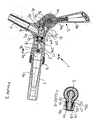
- the handle 5 is biased by the spring 40 to an upright position shown in Figure 2 in which the valve member 33 engages the valve seat 34 to close the valve 6 and prevent fluid flow through the tap body 2.
- the handle 5 is pivotal in the direction of arrow A from the position shown in Figure 2 to the position shown in Figure 3 in which the piston 29 is displaced axially to the right as viewed in Figure 2 to move the valve member 33 away from the valve seat 34 to open the valve 6 and allow fluid to flow from the inlet 3 to the outlet 4.
- Pivotal movement of the handle 5 to open the valve 6 is limited by engagement of the lug 5g with the tap body 2 as shown in Figure 3.
- the lugs 5f,5g are arranged so that the lug 5f comes out of the groove 41 and clears the bore 30 when the valve 6 is fully open as shown in Figure 3.
- the piston 29 is prevented from moving to the left as viewed in Figure 3 under the pressure of the fluid flow through the tap body 2 by engagement of the tail end portion 29a with the recess 5e.
- the lug 5f re-engages the groove 41 to move the piston 29 in a direction to close the valve 6 when the handle 5 is pivoted in the reverse direction either manually or by the spring 40 if the handle 5 is released in the open position of the valve 6.
- the tap body 2 When the tap 1 is to be cleaned, the tap body 2 can be detached from the spigot 7 and the shaft 15 withdrawn to allow the control member 13 to be removed from the inlet 3.
- the piston 29 is uncoupled from the handle 5 by pivoting the handle 5 to the position shown in Figure 3 allowing the piston 29 to be withdrawn from the tap body 2 through the inlet 3 by applying an axial force to the tail end 29a to displace the piston 29 to the right as viewed in Figure 3.
- the piston 29 is re-fitted by a reverse of this operation and is automatically re-coupled to the handle 5 when the handle 5 is pivoted to the position shown in Figure 2. In this way, the valve 6 can be removed, cleaned and re-fitted without detaching the handle 5 from the tap body 2.
- the piston 29 has an internal passageway (not shown) extending from the end of the head portion 29b that communicates with an annular groove 42 adjacent to the abutment shoulder 35 via a radial port (not shown).
- the valve member 33 closes the groove 42 under the biasing of spring 36 to prevent fluid flow through the passageway in both the closed position of the valve 6 shown in Figure 2 and the open position of the valve 6 shown in Figure 3.
- the handle 5 can also be pivoted in the direction of arrow B a short distance beyond the closed position shown in Figure 2 to displace the valve piston 29 axially to the left as viewed in Figure 2.
- the valve member 33 is prevented from moving by engagement with the valve seat 34 and the abutment shoulder 35 moves away from the valve member 33 to expose the annular groove 42 to open the valve 6 and allow a restricted flow of fluid through the head portion 29b to cause foaming and assist the creation of a head on the beverage at the end of a dispense.
- Pivotal movement of the handle 5 to open the passageway is limited by engagement of the lug 5g with the tap body 2.
- the spring 36 is compressed and assists return movement of the handle 5 to the upright position.
- the tap body 2 is provided with an air duct 43 open to atmosphere at one end and communicating with the bore 30 at the other end.
- the tail portion 29a of the piston 29 has an annular groove 44 that aligns with the end of the air duct in the closed position of the valve 6 to open the duct 43 and admit air to drain any fluid remaining in the tap body 2 on the downstream side of the valve 6.
- the duct 43 is closed by the tail portion 29a of the piston 29 either side of the groove 44 on pivotal movement of the handle 5 in either direction from the upright position to open the valve 6 and prevent beverage escaping through the duct 43.
- the handle 5 is operatively connected to the valve 6 so as to be outside the flow of fluid through the tap body 2 and can be pivoted to a position that permits the piston 29 to be removed from the tap body 2 without detaching the handle 5 from the tap body 2.
- the handle 5 is biased to the upright position in which the valve 6 is closed by a spring acting between the tap body 2 and the handle 5 so as to be outside the fluid flow and which provides a positive return action when the handle 5 is pivoted away from the upright position to open the valve 6.
- the compensator 12 can be set in the required position and secured by tightening the lock nut 25 to compress the friction washer and the lock nut 25 concealed with the over cap 28 to inhibit accidental or unauthorised adjustment to alter the set position by bar staff when dispensing a beverage.
Landscapes
- Devices For Dispensing Beverages (AREA)
- Mechanically-Actuated Valves (AREA)
Applications Claiming Priority (2)
| Application Number | Priority Date | Filing Date | Title |
|---|---|---|---|
| GBGB0325558.5A GB0325558D0 (en) | 2003-11-01 | 2003-11-01 | Beverage dispense |
| GB0325558 | 2003-11-01 |
Publications (2)
| Publication Number | Publication Date |
|---|---|
| EP1528036A2 true EP1528036A2 (de) | 2005-05-04 |
| EP1528036A3 EP1528036A3 (de) | 2005-06-22 |
Family
ID=29725805
Family Applications (1)
| Application Number | Title | Priority Date | Filing Date |
|---|---|---|---|
| EP04256724A Withdrawn EP1528036A3 (de) | 2003-11-01 | 2004-10-30 | Zapfhahn für Getränke |
Country Status (2)
| Country | Link |
|---|---|
| EP (1) | EP1528036A3 (de) |
| GB (1) | GB0325558D0 (de) |
Cited By (4)
| Publication number | Priority date | Publication date | Assignee | Title |
|---|---|---|---|---|
| EP1604946A1 (de) * | 2004-06-08 | 2005-12-14 | CMB Schankanlagen GmbH | Zapfhahn für Getränke, insbesondere Biere, mit einer Ausflusstüllenbelüftung |
| WO2007083181A3 (en) * | 2006-01-23 | 2007-11-22 | Vin Service Srl | Delivery spout for beverages |
| ITMI20131278A1 (it) * | 2013-07-30 | 2015-01-31 | Odl Srl | Sistema di controllo della spillatura di bevande gassate e non |
| EP3170788A1 (de) * | 2015-11-19 | 2017-05-24 | Micro Matic A/S | Getränkezapfhahn fur schaumkontrolle |
Family Cites Families (6)
| Publication number | Priority date | Publication date | Assignee | Title |
|---|---|---|---|---|
| FR1136781A (fr) * | 1954-12-21 | 1957-05-20 | Robinet à soupape | |
| GB950077A (en) * | 1960-07-15 | 1964-02-19 | Chadburns Liverpool Ltd | Improvements in or relating to liquid dispensing valves |
| GB1274075A (en) * | 1969-09-08 | 1972-05-10 | Laurie Burdett Kempe | Improvements in or relating to dispensing taps |
| DE2420293A1 (de) * | 1974-04-26 | 1975-11-06 | Willi Trampe | Bierzapfvorrichtung |
| US4869396A (en) * | 1987-08-24 | 1989-09-26 | Kirin Beer Kabushiki Kaisha | Draught beer dispensing system |
| GB2275263B (en) * | 1993-02-17 | 1996-09-04 | Imi Cornelius | Beer dispense |
-
2003
- 2003-11-01 GB GBGB0325558.5A patent/GB0325558D0/en not_active Ceased
-
2004
- 2004-10-30 EP EP04256724A patent/EP1528036A3/de not_active Withdrawn
Cited By (9)
| Publication number | Priority date | Publication date | Assignee | Title |
|---|---|---|---|---|
| EP1604946A1 (de) * | 2004-06-08 | 2005-12-14 | CMB Schankanlagen GmbH | Zapfhahn für Getränke, insbesondere Biere, mit einer Ausflusstüllenbelüftung |
| WO2007083181A3 (en) * | 2006-01-23 | 2007-11-22 | Vin Service Srl | Delivery spout for beverages |
| ITMI20131278A1 (it) * | 2013-07-30 | 2015-01-31 | Odl Srl | Sistema di controllo della spillatura di bevande gassate e non |
| WO2015015275A1 (en) | 2013-07-30 | 2015-02-05 | O.D.L. S.R.L. | Control system for a beverage dispenser |
| DE212014000162U1 (de) | 2013-07-30 | 2016-04-01 | O.D.L. S.R.L. | Steuerungssystem für Ausschank und Lagerung von Getränken |
| EP3170788A1 (de) * | 2015-11-19 | 2017-05-24 | Micro Matic A/S | Getränkezapfhahn fur schaumkontrolle |
| WO2017085261A1 (en) * | 2015-11-19 | 2017-05-26 | Micro Matic A/S | Beverage dispensing unit with a dispensing valve having a piston |
| CN108430909A (zh) * | 2015-11-19 | 2018-08-21 | 微马蒂奇股份公司 | 包括具有活塞的分配阀的饮料分配单元 |
| RU2744368C2 (ru) * | 2015-11-19 | 2021-03-05 | Микро Матик А/С | Дозирующий узел для напитков |
Also Published As
| Publication number | Publication date |
|---|---|
| GB0325558D0 (en) | 2003-12-03 |
| EP1528036A3 (de) | 2005-06-22 |
Similar Documents
| Publication | Publication Date | Title |
|---|---|---|
| EP1847508B1 (de) | Getränkeausgabeventil | |
| AU2012233151B2 (en) | Creamy foam beer dispensing system | |
| US7264016B2 (en) | Self-closing rotary valve | |
| US10589978B2 (en) | Beverage dispensers with dual flow dispensing valves | |
| US8016168B2 (en) | Dispense valve | |
| IE852856L (en) | Dispensing tap | |
| EP3614036B1 (de) | Anschlussvorrichtung für einen gasdruckbehälter | |
| DE20321260U1 (de) | Bierabgabegerät | |
| US7775462B2 (en) | Spray device | |
| US6478200B1 (en) | Beverage dispense device | |
| EP1412280A1 (de) | Vorrichtung und verfahren zum verbinden eines behälters an einer druckquelle | |
| GB2436558A (en) | Beverage dispense valve | |
| ZA200503103B (en) | Sanitary faucet with improved flow restriction feature and foam control feature | |
| GB2489953A (en) | A beverage dispense apparatus dispensing the required amount of foam | |
| EP1236677B1 (de) | Vorrichtung zur beschützten Einstellung einer Durchflussreguliereinrichtung in Getränkeabgabeanlagen | |
| CZ308189B6 (cs) | Zařízení pro čepování piva | |
| IES20060250A2 (en) | Beverage dispense valve | |
| WO2023000035A1 (en) | Flow control faucet for a beverage dispensing system | |
| CZ36310U1 (cs) | Výčepní kohout | |
| CZ9903247A3 (cs) | Zařízení pro čepování piva | |
| ES2932202A1 (es) | Grifo dispensador de bebidas | |
| IE20060250U1 (en) | Beverage dispense valve | |
| JPH0735887Y2 (ja) | 水 栓 | |
| IES84844Y1 (en) | Beverage dispense valve | |
| AU2021201593A1 (en) | Beverage tap |
Legal Events
| Date | Code | Title | Description |
|---|---|---|---|
| PUAI | Public reference made under article 153(3) epc to a published international application that has entered the european phase |
Free format text: ORIGINAL CODE: 0009012 |
|
| AK | Designated contracting states |
Kind code of ref document: A2 Designated state(s): AT BE BG CH CY CZ DE DK EE ES FI FR GB GR HU IE IT LI LU MC NL PL PT RO SE SI SK TR |
|
| AX | Request for extension of the european patent |
Extension state: AL HR LT LV MK |
|
| PUAL | Search report despatched |
Free format text: ORIGINAL CODE: 0009013 |
|
| AK | Designated contracting states |
Kind code of ref document: A3 Designated state(s): AT BE BG CH CY CZ DE DK EE ES FI FR GB GR HU IE IT LI LU MC NL PL PT RO SE SI SK TR |
|
| AX | Request for extension of the european patent |
Extension state: AL HR LT LV MK |
|
| AKX | Designation fees paid | ||
| REG | Reference to a national code |
Ref country code: DE Ref legal event code: 8566 |
|
| STAA | Information on the status of an ep patent application or granted ep patent |
Free format text: STATUS: THE APPLICATION IS DEEMED TO BE WITHDRAWN |
|
| 18D | Application deemed to be withdrawn |
Effective date: 20051223 |