EP1528128A2 - Râtelier porte-bobines pour machines textiles - Google Patents
Râtelier porte-bobines pour machines textiles Download PDFInfo
- Publication number
- EP1528128A2 EP1528128A2 EP04018187A EP04018187A EP1528128A2 EP 1528128 A2 EP1528128 A2 EP 1528128A2 EP 04018187 A EP04018187 A EP 04018187A EP 04018187 A EP04018187 A EP 04018187A EP 1528128 A2 EP1528128 A2 EP 1528128A2
- Authority
- EP
- European Patent Office
- Prior art keywords
- thread
- slot opening
- aufsteckdome
- creel
- axes
- Prior art date
- Legal status (The legal status is an assumption and is not a legal conclusion. Google has not performed a legal analysis and makes no representation as to the accuracy of the status listed.)
- Withdrawn
Links
- 239000004753 textile Substances 0.000 title description 3
- 210000000056 organ Anatomy 0.000 abstract description 5
- 230000007246 mechanism Effects 0.000 description 2
- 238000000034 method Methods 0.000 description 2
- 230000007704 transition Effects 0.000 description 2
- 238000010276 construction Methods 0.000 description 1
- 230000000630 rising effect Effects 0.000 description 1
Images

Classifications
-
- D—TEXTILES; PAPER
- D01—NATURAL OR MAN-MADE THREADS OR FIBRES; SPINNING
- D01H—SPINNING OR TWISTING
- D01H1/00—Spinning or twisting machines in which the product is wound-up continuously
- D01H1/14—Details
- D01H1/18—Supports for supply packages
-
- D—TEXTILES; PAPER
- D01—NATURAL OR MAN-MADE THREADS OR FIBRES; SPINNING
- D01H—SPINNING OR TWISTING
- D01H13/00—Other common constructional features, details or accessories
- D01H13/04—Guides for slivers, rovings, or yarns; Smoothing dies
Definitions
- the invention relates to a creel with at least two superimposed Bobbin domes attached to a machine frame attached Mounted between a lower loading station and an upper operating position is pivotable.
- a creel is for example, in FR-A-2 794 136.
- a described in DE-AS 1 145 527 coil holder is designed so that during rewinding of yarns after expiry of a delivery reel, a standstill thereby To avoid that the expiration process is designed continuously by the thread end of the delivery bobbin with the thread beginning of a reserve coil connected is.
- one is with several, for example two Arranged on spiked spool holder provided around a centric between the two Aufsteckdomen axis is rotatable.
- a creel described in US 1,180,284 contains several side by side and one above the other arranged arbors for drain coils, wherein each two coils are associated with each other so that the yarn end of the a bobbin with the thread beginning a second, a reserve coil forming drain coil is connected.
- the individual arbors are with in essential upwardly oriented axes whereby in particular the Attachment of original or processing bobbins is difficult to a holder attached, which is about a horizontal axis from a substantially vertical Position in an obliquely upward position towards the front of the machine pivotal in the effort, the exchange empty-wound coils to facilitate new reserve spools.
- Each arbor pair for two too a drain unit associated coils are for an orderly Thread withdrawal on the one hand above the arbors and the other side of the Arranged on arbors arranged yarn guide eyelets. It concerns with this known creel to such, in the not generic to at least two superposed Spulen Aufsteckdome the present invention for associated with one another on a machine frame Attached bracket are mounted between a lower bracket Loading station and an upper operating position is pivotable.
- the invention is based on the object, a creel according to the preamble of patent claim 1 to be designed so that it compared to that in DE-AS 1 145 527 described creel has a simplified construction to after the emptying of a drain spool in a reliable way the deduction of Thread from the second, a spare spool forming drain spool guarantee.
- Figure 1 shows a schematic representation of a side view of a machine in the longitudinal direction provided on both sides with jobs textile machine, for example Cabling machine, at the top of each opposite Machine side serving creel 3,3 'are pivotally mounted;
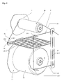
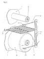
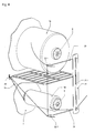
- Figures 2 to 4 show a schematic representation of individual elements of the yarn transfer device and the threadline during the transition of the thread withdrawal from a feed bobbin to a second feed bobbin.
- the textile machine 1 shown only schematically in FIG. 1 is for example, a machine longitudinal direction on both sides with Kablierspindeln 2 equipped cabling machine.
- the one associated with a single Kablierspindel 2 Bobbin creel 3 is for example by means of a four-bar linkage 4 at the top the machine frame 5 pivotally mounted.
- the single creel 3 may be formed in a conventional manner as a double creel, such that each creel can be loaded or loaded with four supply spools Sp, so that in each case two adjacent Kablierspindeln the cabling of a individual creels can be operated.
- the creel 3 includes a support plate 6, on both sides of each one is attached substantially vertically aligned holding plate 7, the two vertically superimposed and after aligned Aufsteckdome 8 for attachment of supply spools Sp bears.
- the Aufsteckdome 8 are opposite to the horizontal by an angle in the range of 5-10 ° after rising from inclined placed in order to ensure a secure fit of the plugged spool Sp.
- a directed arm 9 which is a Fadenumlenkinate 10 carries to the withdrawn from the individual supply spool Sp thread F 1 to the lower machine area, d. H. towards the cabling spindle 2, redirect.
- This thread F 1 is in accordance with the usual Kablierprozeß in Area of the thread guide eye 11 with the thread F2 united, the overhead of a withdrawn within the cabling spindle 2 feed bobbin is deducted.
- Above the Kablierspindel is in the usual way a yarn delivery mechanism 12 and a Fadenaufwickelaggregat 13 stored.
- a thread guide member 21 forming plate is attached, the is provided with a slot opening 21.1, the length of which is substantially the vertical distance between the axes of Aufsteckdorne 8 corresponds.
- the Plate 21 is positioned so that the ends of the slot opening in the Extension of the axes of arbors 8 are located.
- the plate 21 carries two elongated Fadenleitorgane 22, 23, which at the Aufsteckdomen 8 facing Side of the plate 21 in the region of the ends of the slot opening laterally next to the Slot opening 21.1 attached and aligned so that they Cross slot opening.
- the single Fadenleitorgan 22 or 23 is in essentially from a wire fastened with its one end to the plate 21, which is bent at its free end to a hook 22.1 or 23.1, the one laterally in the direction of the slot opening 21.1 forms an open eyelet.
- Every thread guide organ 22 and 23 has a length such that the thread eye forming Hooks 22.1 and 23.1 substantially outside the maximum coil diameter which is foundedsteckenden on the Aufsteckdome coil Sp.
- the thread guide organs 22 and 23 are just before the ends of the slot opening 21.1 at the Plate 21 attached such that these Fadenleitorgane 22 and 23 in the region of Ends of the slot opening 21.1 with these one in the extension of Aufsteckdomachsen Limit lying thread withdrawal opening.
- a Separator Assembly 25 attached on the holding plate 7 is centrally between the Aufsteckdomen 8 a Separator Structure 25 attached.
- a thread holding member 24th attached, which is preferably designed as a thread clamp and at least one resiliently against a support member 24.1 fitting clamping tongue 24.2 contains.
- the Holding force of the yarn holding member 24 is set so that it slightly below the Tensile force is at which the thread F is subtracted from the supply spool Sp, such that a held by this thread-holding member 24 thread released is, if on him one of the trigger tension of the thread F corresponding tensile force is exercised.
- Figure 2 shows a state in which a thread F from an upper original spool Sp is withdrawn just before it is unwound.
- the one from the upper coil In this case, thread F drawn off over the head is in the area of the upper end the slot opening 21.1 located opening deducted, the down is limited by the upper wire-shaped Fadenleitorgan 23. That of the upper one Coil coming, expiring thread end is fully wound with that of the lower Coil coming thread beginning at Fn connected.
- the between the two coils located thread section is inserted into the yarn holding member 24 and from above to put around the hook 23.1 and then to the placed lower hooks 22.1.
- FIG. 4 For the thread change or the thread transfer from a lower supply spool too an upper feed bobbin is shown in FIG. 4 that of the thread reserve of the lower Coil coming outgoing thread end in an analogous manner to Figure 2 with connected to the beginning of the upper, fully wound coil thread beginning.
- the thread section located between the two coils is in the thread holding member 24 inserted and then from the outside and below inwards and upwards wrapped around the hook 22.1 and then from the bottom and inside up and inserted outside in the upper hooks 23.1.
- the Spulenaufsteckdome are preferably in lateral Direction swiveling.
Landscapes
- Engineering & Computer Science (AREA)
- Mechanical Engineering (AREA)
- Textile Engineering (AREA)
- Yarns And Mechanical Finishing Of Yarns Or Ropes (AREA)
- Unwinding Of Filamentary Materials (AREA)
- Guides For Winding Or Rewinding, Or Guides For Filamentary Materials (AREA)
- Spinning Or Twisting Of Yarns (AREA)
Applications Claiming Priority (2)
| Application Number | Priority Date | Filing Date | Title |
|---|---|---|---|
| DE10348279A DE10348279A1 (de) | 2003-10-17 | 2003-10-17 | Spulengatter für Textilmaschinen |
| DE10348279 | 2003-10-17 |
Publications (1)
| Publication Number | Publication Date |
|---|---|
| EP1528128A2 true EP1528128A2 (fr) | 2005-05-04 |
Family
ID=34399536
Family Applications (1)
| Application Number | Title | Priority Date | Filing Date |
|---|---|---|---|
| EP04018187A Withdrawn EP1528128A2 (fr) | 2003-10-17 | 2004-07-31 | Râtelier porte-bobines pour machines textiles |
Country Status (5)
| Country | Link |
|---|---|
| US (1) | US20050082404A1 (fr) |
| EP (1) | EP1528128A2 (fr) |
| JP (1) | JP2005119881A (fr) |
| CN (1) | CN1609293A (fr) |
| DE (1) | DE10348279A1 (fr) |
Cited By (2)
| Publication number | Priority date | Publication date | Assignee | Title |
|---|---|---|---|---|
| EP1760174A2 (fr) | 2005-08-18 | 2007-03-07 | Saurer GmbH & Co. KG | Machine textile pour la fabrication des bobines de fil retordu |
| EP2893065A4 (fr) * | 2012-09-07 | 2016-04-27 | American Linc Llc | Ensemble cantre conçu pour porter de multiples enroulements de fil mutuellement reliés dans une pluralité de postes d'enroulement verticalement espacés |
Families Citing this family (7)
| Publication number | Priority date | Publication date | Assignee | Title |
|---|---|---|---|---|
| JP2011226031A (ja) * | 2010-04-22 | 2011-11-10 | Murata Mach Ltd | 紡績機 |
| CN103614818B (zh) * | 2013-12-11 | 2016-03-16 | 宜昌经纬纺机有限公司 | 气动高低纱架 |
| US10472199B1 (en) * | 2016-09-09 | 2019-11-12 | American Linc, Llc | Creel safety latch, overhead bobbin creel, and method for loading and unloading an overhead bobbin creel |
| DE202017106858U1 (de) * | 2017-11-10 | 2019-02-13 | Saurer Germany Gmbh & Co. Kg | Arbeitsstelle einer Doppeldrahtzwirn- oder Kabliermaschine zur Herstellung von Teppichgarn |
| USD968476S1 (en) | 2019-06-18 | 2022-11-01 | Saurer Technologies GmbH & Co. KG | Textile machine |
| CN111891820A (zh) * | 2020-07-14 | 2020-11-06 | 安徽华茂纺织股份有限公司 | 有利于降低s捻筒纱退绕断头数的方法 |
| JP7618519B2 (ja) * | 2021-08-20 | 2025-01-21 | Tmtマシナリー株式会社 | 糸加工設備 |
Family Cites Families (8)
| Publication number | Priority date | Publication date | Assignee | Title |
|---|---|---|---|---|
| US1180284A (en) * | 1915-07-26 | 1916-04-25 | American Thread Co | Creel. |
| US1538956A (en) * | 1924-12-04 | 1925-05-26 | David S Seaman | Process or method and apparatus for spinning or twisting and winding yarn |
| DE1145527B (de) * | 1955-11-03 | 1963-03-14 | Reiners Walter Dr Ing | Spulenhalter |
| US4163357A (en) * | 1977-06-13 | 1979-08-07 | Hamel Gmbh, Zwirnmaschinen | Apparatus for cable-twisting two yarns |
| FR2418762A1 (fr) * | 1978-03-02 | 1979-09-28 | Verdol Sa | Cantre perfectionne pour machine a retordre |
| US4240594A (en) * | 1979-03-16 | 1980-12-23 | Rca Corporation | Creel |
| US4464891A (en) * | 1979-04-17 | 1984-08-14 | Manly Jr W Judson | Yarn processing machine and creel assembly |
| DE68902801T2 (de) * | 1988-07-25 | 1993-01-14 | Picanol Nv | Schussfadenzufuehrvorrichtung an webmaschinen. |
-
2003
- 2003-10-17 DE DE10348279A patent/DE10348279A1/de not_active Withdrawn
-
2004
- 2004-07-31 EP EP04018187A patent/EP1528128A2/fr not_active Withdrawn
- 2004-09-20 CN CNA2004100780480A patent/CN1609293A/zh active Pending
- 2004-10-15 US US10/966,500 patent/US20050082404A1/en not_active Abandoned
- 2004-10-15 JP JP2004301665A patent/JP2005119881A/ja active Pending
Cited By (2)
| Publication number | Priority date | Publication date | Assignee | Title |
|---|---|---|---|---|
| EP1760174A2 (fr) | 2005-08-18 | 2007-03-07 | Saurer GmbH & Co. KG | Machine textile pour la fabrication des bobines de fil retordu |
| EP2893065A4 (fr) * | 2012-09-07 | 2016-04-27 | American Linc Llc | Ensemble cantre conçu pour porter de multiples enroulements de fil mutuellement reliés dans une pluralité de postes d'enroulement verticalement espacés |
Also Published As
| Publication number | Publication date |
|---|---|
| JP2005119881A (ja) | 2005-05-12 |
| US20050082404A1 (en) | 2005-04-21 |
| CN1609293A (zh) | 2005-04-27 |
| DE10348279A1 (de) | 2005-05-25 |
Similar Documents
| Publication | Publication Date | Title |
|---|---|---|
| DE4420979B4 (de) | Fadenendevorbereitungseinrichtung für Kreuzspulen herstellende Textilmaschinen | |
| DE2648621C3 (de) | Doppeldraht-Zwirnmaschine | |
| DE3602574C2 (de) | Kreuzspulen herstellende Maschine mit Vorrichtung zur Bildung einer Fadenendreserve auf einer fertig gewickelten Spule | |
| DE102016002695A1 (de) | Fadenspleißvorrichtung für eine Arbeitsstelle einer Kreuzspulen herstellenden Textilmaschine | |
| DE2543986A1 (de) | Verfahren und vorrichtung zur sicherung einer reservewicklung auf einer spulenhuelse | |
| DD299664A5 (de) | Betriebsverfahren und vorrichtung zum automatisierten auswechseln von auflaufspulen, insbesondere zwirnkreuzspulen, gegen leere aufwickelhuelsen | |
| EP1528128A2 (fr) | Râtelier porte-bobines pour machines textiles | |
| DE2710821C3 (de) | Fadenliefervorrichtung für Textilmaschinen | |
| DE2118443A1 (de) | Vorrichtung zum Aufnehmen, Bereithalten und Abspulen von Garnkörpern an Textilmaschinen | |
| DE2744424B2 (de) | Spiniunaschinenrahmen | |
| DE69826230T2 (de) | Aufwickelmaschine für elastischen Faden und Wickel | |
| DE2357430C3 (de) | Fadenführungs- und Überwachungsvorrichtung an einem Schär- und Zettelgatter | |
| DE2443616C3 (de) | Automatische an Ringspinnmaschinen verfahrbare Einfädelvorrichtung | |
| DE10050693A1 (de) | Hülsenzubringer für eine Arbeitsstelle einer Kreuzspulen herstellenden Textilmaschine | |
| DE4125107A1 (de) | Spulenhuelsenaufnahmevorrichtung | |
| EP0534121A1 (fr) | Dispositif pour enrouler un fil sur une bobine | |
| DE2330961C3 (de) | Vorrichtung zur Bildung einer Fadenreserve auf einer Aufwickelspule mit wilder Wicklung an schnellaufenden Spulmaschinen | |
| DE19524946B4 (de) | Kreuzspulen herstellende Textilmaschine | |
| WO1982001540A1 (fr) | Procede et dispositif pour introduire des fils et similaires dans une machine a bobiner | |
| DE2726603B2 (de) | Aufwärtszwirnmaschine | |
| EP0521816A1 (fr) | Procédé pour transferer le fil d'une bobine pleine à une bobine vide et un bobinoir | |
| DE3924000C2 (fr) | ||
| DE3604658C2 (fr) | ||
| DE1226465B (de) | Vorrichtung zum Wechseln der Aufwickelspulen bei mit grosser Geschwindigkeit arbeitenden Garn- bzw. Fadenwickelmaschinen | |
| EP0092511A2 (fr) | Procédé de formation d'une réserve de fil sans vrilles ainsi qu'une machine de bobinage |
Legal Events
| Date | Code | Title | Description |
|---|---|---|---|
| PUAI | Public reference made under article 153(3) epc to a published international application that has entered the european phase |
Free format text: ORIGINAL CODE: 0009012 |
|
| AK | Designated contracting states |
Kind code of ref document: A2 Designated state(s): AT BE BG CH CY CZ DE DK EE ES FI FR GB GR HU IE IT LI LU MC NL PL PT RO SE SI SK TR |
|
| AX | Request for extension of the european patent |
Extension state: AL HR LT LV MK |
|
| STAA | Information on the status of an ep patent application or granted ep patent |
Free format text: STATUS: THE APPLICATION HAS BEEN WITHDRAWN |
|
| 18W | Application withdrawn |
Effective date: 20060504 |