EP1528181A1 - Doppelboden - Google Patents
Doppelboden Download PDFInfo
- Publication number
- EP1528181A1 EP1528181A1 EP04292481A EP04292481A EP1528181A1 EP 1528181 A1 EP1528181 A1 EP 1528181A1 EP 04292481 A EP04292481 A EP 04292481A EP 04292481 A EP04292481 A EP 04292481A EP 1528181 A1 EP1528181 A1 EP 1528181A1
- Authority
- EP
- European Patent Office
- Prior art keywords
- longitudinal
- slabs
- longitudinal members
- floor
- floor according
- Prior art date
- Legal status (The legal status is an assumption and is not a legal conclusion. Google has not performed a legal analysis and makes no representation as to the accuracy of the status listed.)
- Withdrawn
Links
Images

Classifications
-
- E—FIXED CONSTRUCTIONS
- E04—BUILDING
- E04F—FINISHING WORK ON BUILDINGS, e.g. STAIRS, FLOORS
- E04F15/00—Flooring
- E04F15/02—Flooring or floor layers composed of a number of similar elements
- E04F15/024—Sectional false floors, e.g. computer floors
- E04F15/02447—Supporting structures
- E04F15/02452—Details of junctions between the supporting structures and the panels or a panel-supporting framework
-
- E—FIXED CONSTRUCTIONS
- E04—BUILDING
- E04F—FINISHING WORK ON BUILDINGS, e.g. STAIRS, FLOORS
- E04F15/00—Flooring
- E04F15/02—Flooring or floor layers composed of a number of similar elements
- E04F15/024—Sectional false floors, e.g. computer floors
- E04F15/02447—Supporting structures
- E04F15/02458—Framework supporting the panels
-
- E—FIXED CONSTRUCTIONS
- E04—BUILDING
- E04F—FINISHING WORK ON BUILDINGS, e.g. STAIRS, FLOORS
- E04F15/00—Flooring
- E04F15/02—Flooring or floor layers composed of a number of similar elements
- E04F15/024—Sectional false floors, e.g. computer floors
- E04F15/02447—Supporting structures
- E04F15/02464—Height adjustable elements for supporting the panels or a panel-supporting framework
- E04F15/0247—Screw jacks
Definitions
- the invention generally relates to the field of raised floors.
- the invention relates to a floor raised to be installed at a certain height above a floor, this floor including feet resting on the ground arranged along several lines parallel to a longitudinal direction, longitudinal members longitudinal resting on the feet and arranged next said parallel lines, transverse cross members extending between the longitudinal members, and slabs resting at less on the spars and sleepers.
- Floors of this type have been known for over 40 years. As shown in Figure 1, they include typically checkered feet with height-adjustable support heads with respect to ground. The rails and cross members are fixed by their respective ends on the support heads. The slabs are square and all show the same dimensions. Each rests by its four-headed corners of support, and by its edges on two longitudinal members and two sleepers.
- the sleepers and spars are identical and are slotted section profiles. Faces lower slabs rest on the upper sides profiles, such that these profiles extend entirely under the slabs.
- the present invention aims to to present a raised floor concept that breaks radically with the type of floor used since 40 years, and which overcomes the defects mentioned above.
- the device of the invention for otherwise consistent with the generic definition given in the preamble above is essentially characterized in that the longitudinal members are profiles comprising a longitudinal central core, and two longitudinal wings extending transversely from a part bottom of the central core of both transverse sides opposite of this soul, the slabs resting on the wings spars.
- the beams are ⁇ -shaped profiles, the core central having a U-shaped section open to the ground, this section with opposite ends extended transversely towards the outside of the U by the wings.
- the central souls of the side members have a height substantially equal to the thickness slabs, so that these central souls extend in the thickness of the slabs.
- the feet each comprise a base resting on the ground, a threaded rod extending from the base in a vertical direction substantially perpendicular to the longitudinal directions transverse, and a support plate with a threaded hole in which the threaded rod is engaged, the spars resting on the support plates by their respective wings.
- the threaded rod has one end free engaged in the central core of the spar.
- the two opposite wings of the side members each comprise a longitudinal flange drawn towards the floor, the support plates being arranged between the raised edges of two opposite wings of the same spar.
- the sleepers have the same general shape as the longitudinal members, the slabs also resting on the wings sleepers.
- the sleepers rest with respective ends on the wings of the side members.
- spars and sleepers are preferably made of steel one millimeter thick minimum.
- the central souls of the side members and / or sleepers have sections of shapes general parallelepipedal or trapezoidal.
- feet can be irregularly spaced along at least one line longitudinal.
- the floor may include slabs of first longitudinal length and slabs of second longitudinal length different from the first.
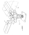
- the floor 1 shown in FIG. 2 is a raised technical floor, intended to be installed in a certain height above a floor 2 so as to allow the passage of high current electrical cables or weak current, of pipes, of sheaths ventilation or other networks between the floor and the ground.
- This floor 1 comprises feet 10 resting on the floor 2 arranged along several lines parallel to a longitudinal direction X-X ', longitudinal longitudinal members 20 resting on the feet 10 and arranged according to said parallel lines, cross ties 50 extending between the longitudinal members 20, and slabs 60 resting on at least the longitudinal members 20 and the sleepers 50.
- Slabs 60 are typically made of particles of agglomerated wood, and exhibit a strong density. They can be provided on one side upper 61 opposed to the floor 2 of a coating chosen in according to the use of the floor. This coating can for example, laminate, vinyl, linoleum, rubber, textile, mineral, ceramic or parquet.
- These slabs 60 are parallelepipedic and have two longitudinal straight edges 62 and two transverse straight edges 63.
- the longitudinal members 20 are metal sections comprising a central core 30 longitudinal, and two longitudinal wings 40 extending transversely from a lower part of the central core 30, of the two opposite transverse sides of this soul.
- the lower part of the central core 30 is relatively closer to the ground 2, the central core 30 comprising a relatively higher upper part far from the ground 2 having a free upper face 31 plane turned one side opposite the ground 2.
- the slabs 60 rest on the wings 40 of the longitudinal members 20 by their two longitudinal edges 62 opposed. Slabs 60 rest on lower faces respective opposing upper faces 61 on one side wings 40 opposite the ground 2.
- the longitudinal members 20 are ⁇ profiles, the central core 30 having perpendicular to the longitudinal direction a U section open to the ground 2.
- This section has opposite 32 ends extended transversely towards the outside of the U by the wings 40.
- the two wings 40 extend in the same plane.
- the central webs 30 of the longitudinal members 20 have, along a vertical axis perpendicular to the directions longitudinal and transverse, a height substantially equal to the thickness of the slabs 60.
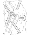
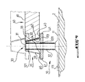
- the central souls 30 thus extend into the thickness of slabs 60, their free upper faces 31 being exactly in the extension of the faces upper 61 slabs 60 as shown in Figure 3.
- feet 10 each comprise a base 11 resting on the ground 2, a threaded rod 12 extending from the base 11 into the vertical direction, and a support plate 13 having a threaded orifice 131 in which the rod Threaded 12 is engaged.
- the height of floor 1 above ground 2 is adjusted by moving the plate 13 along the rod threaded 12, by rotation of this plate 13 in the direction adequate.
- the support plate 13 is a steel plate massive, of thickness between 5 and 10 millimeters. It has an elongated rectangular shape in the longitudinal direction, its transverse width being substantially equal to the transverse width of the spar 20.
- the transverse width of the spar 20 corresponds to the spacing between respective outer edges of two wings 40 of this spar 20, the outer edges being the opposite edges to the central core 30.
- the longitudinal members 20 rest on the plates of support 13 by their respective wings 40, and more precisely by the lower sides of these wings 40 turned to the ground 2.
- the outer edges of the two opposed wings 40 of the same spar each have a longitudinal flange 41 raised to the ground 2, the support plates 13 being arranged between the raised edges 41 of the two wings 40 opposite of the same spar.
- the plate 13 thus extends along the edges raised 41, in contact therewith.
- the spar 20 is blocked in translation transversely relative to the plate 13, but is free in translation longitudinally relative to this plate.
- Support plate 13 serves then guide in translation to the spar 20.
- the threaded rod 12 has a free end 121 which, in certain positions vertical of the plate 13 along the rod 12, made protruding above this plate 13. This end 121 is then engaged inside the central core 30 of spar 20.
- the base 11 of the foot 10 is a steel plate round, with holes 111.
- This base is rigidly fixed on the floor 2, for example by screws, no represented, engaged in holes 111.
- This plate may also have a square shape, or any other shape adapted to the environment where the foot is placed.
- the sleepers 50 have the same general shape that the longitudinal members 20. These are metal profiles in ⁇ , provided with a central transverse core, and two 40 transverse wings extending longitudinally to from the central core 30, on both longitudinal sides opposite of this soul.
- the central core 30 of the crosspiece 50 presents perpendicular to the transverse direction a open U-shaped section 2, the ends of which 32 opposites are extended longitudinally towards the outside of the U by the wings 40.
- the two wings 40 extend in the same plane.
- the central core 30 is provided with an upper face free 31 plane turned to a side opposite the ground 2.
- the outer edges of the wings 40 bear ledges 41 raised to the ground 2.
- the slabs 60 rest on the wings 40 of the crosspieces 50 by their two transverse edges 63 opposed.
- the slabs 60 rest on one side of the wings 40 opposite to the ground 2.
- Each crossmember 50 rests by ends opposite transverses on the wings 40 of two longitudinal members 20.
- the led edges 41 of the wings 40 stop at a distance from transverse ends of the crossbar 50.
- the wings 40 of the crosspiece 50 rest, at both ends thereof, by a lower side on an upper side of the wing 40 of a spar 20.
- the central webs 30 of the sleepers 50 have, along the vertical axis, a height substantially equal to the thickness of slabs 60.
- the central souls 30 of the sleepers 50 extend and in the thickness of slabs 60, their faces free upper 31 being exactly in the extension of the upper faces 61 of the slabs 60 as shown in Figure 3.
- the longitudinal members 20 and the cross members 50 are of preferably made of steel one millimeter thick minimum. They can also be realized in other metals, for example aluminum, the thickness of the metal being chosen according to the size of the slabs and the load to bear.
- central souls 40 of the longitudinal members 20 and / or sleepers 50 have sections of general parallelepipedal or trapezoidal forms.
- the sections of the central webs 40 of the side members 20 and sleepers 50 are preferably identical.
- the central core 30 comprises a top sail defining the upper free face 31, and two sails lateral 32 extending symmetrically with respect to a median vertical plane of the central core 30. These sails lateral 32 connect the upper veil to the wings 40.
- lateral sails 32 are planar. When the soul Central is of parallelepipedal section, the sails 32 are mutually parallel, and are perpendicular to the upper veil. When the central soul is of trapezoidal section, lateral sails extend divergently from the veil upper to the wings 40.
- the longitudinal 62 and transverse edges 63 of the slabs 60 are pressed against the sails 32 respectively longitudinal members 20 and cross members 50.
- the edges of slabs 60 are rights.
- the edges of slabs 60 are bevelled, and are inclined towards the inside of the slab 60 from its upper face 61.
- the floor structure is therefore reinforced precisely in the areas where slabs are particularly fragile, that is to say along their edges.
- slabs of 20 are used in the invention. millimeters thick only. In addition, these slabs do not need to be reinforced with a steel tray dressing their underside and their edges.
- the feet of several different ways can, as in the prior art, support the ends of two contiguous spars.
- the feet can be arranged at a distance from the ends of the spar, for example one to a quarter of the length longitudinal and one to three quarters of the length longitudinal of the spar.
- the feet are arranged in checkerboard and always present the same longitudinal spacing. This spacing corresponds to the length of the spars.
- the invention makes it possible to dissociate the length of foot rails, since it is possible to place several support legs along of the same spar. We can therefore use side members long distances without compromising the resistance of the floor. This resistance is preserved by arranging the along the spar a sufficiently large number of feet, these feet being separated by an adequate spacing.
- the invention also makes it easy to use rectangular slabs. It allows in particular to integrate in the same floor slabs 60 with transversely the same width and lengthwise different lengths.
- floor 1 includes slabs 60 of first length longitudinal and slabs 60 of second length longitudinal, the second length being twice the first.
- the side members 20 are arranged according to several mutually parallel lines and spacing transversal constant.
- the sleepers 50 are positioned between two adjacent lines, with corresponding to either the first or the second longitudinal length. It is very easy to adjust this longitudinal spacing since the sleepers 50 simply rest on the wings of rails and can slide freely along them.
- slabs of floor described above may be made other materials than chipboard without leaving the framework of the invention.
- the slabs can for example be made of calcium silicate.
- the installation height of the floor above the soil is reduced. This result is achieved first of all by the slab thickness but also because the sleepers and the longitudinal members are arranged in the thickness slabs and not below them.
- the height of installation corresponds to the height that it is necessary to leave free for the passage of networks, the height of the slabs, spars and sleepers.
- the range of adjustment of the height of the support plate along the foot is larger in the invention than in the prior art.
- the free end of the threaded rod may protrude above of the plaque because it is lodged inside of the central core of the spars.
- the plates rest directly on the heads of support.
- the threaded rods of the feet can not to go above the heads. We can hardly move your head down from the end free of the threaded rod.
- the invention also allows great flexibility for slab size, especially in the direction longitudinal.
Landscapes
- Engineering & Computer Science (AREA)
- Architecture (AREA)
- General Engineering & Computer Science (AREA)
- Civil Engineering (AREA)
- Structural Engineering (AREA)
- Floor Finish (AREA)
Applications Claiming Priority (2)
| Application Number | Priority Date | Filing Date | Title |
|---|---|---|---|
| FR0312599A FR2861412B1 (fr) | 2003-10-28 | 2003-10-28 | Plancher sureleve de conception amelioree. |
| FR0312599 | 2003-10-28 |
Publications (1)
| Publication Number | Publication Date |
|---|---|
| EP1528181A1 true EP1528181A1 (de) | 2005-05-04 |
Family
ID=34400852
Family Applications (1)
| Application Number | Title | Priority Date | Filing Date |
|---|---|---|---|
| EP04292481A Withdrawn EP1528181A1 (de) | 2003-10-28 | 2004-10-19 | Doppelboden |
Country Status (2)
| Country | Link |
|---|---|
| EP (1) | EP1528181A1 (de) |
| FR (1) | FR2861412B1 (de) |
Cited By (4)
| Publication number | Priority date | Publication date | Assignee | Title |
|---|---|---|---|---|
| EP2354371A1 (de) | 2010-01-22 | 2011-08-10 | Subfloor ApS | Stützsystem für einen Fußboden |
| ITMI20130278A1 (it) * | 2013-02-26 | 2014-08-27 | Belink S A | Struttura di supporto |
| FR3007052A1 (fr) * | 2013-06-18 | 2014-12-19 | Wilfried Andres | Dispositif support de type plot pour la construction de terrasses. |
| EP3196382A1 (de) * | 2016-01-19 | 2017-07-26 | R&M International GmbH | Schalldämmender boden, insbesondere für schiffe |
Citations (5)
| Publication number | Priority date | Publication date | Assignee | Title |
|---|---|---|---|---|
| US4901490A (en) * | 1984-12-17 | 1990-02-20 | Gabalan Corporation | Raised flooring panel and raised flooring assemblies |
| US5048242A (en) * | 1990-04-04 | 1991-09-17 | C-Tec, Inc. | Access floor system with hemmed edge panel |
| FR2724403A1 (fr) * | 1994-09-14 | 1996-03-15 | Bouche Michel | Faux plancher pour local technique, salle informatique notamment |
| DE19607511A1 (de) * | 1995-04-12 | 1996-10-17 | Beat Cadosch | Doppelboden |
| EP0770743A1 (de) * | 1995-10-24 | 1997-05-02 | SICOWA Verfahrenstechnik für Baustoffe GmbH & Co. KG | Stützenanordnung für einen Installationsboden |
Family Cites Families (4)
| Publication number | Priority date | Publication date | Assignee | Title |
|---|---|---|---|---|
| GB1140957A (en) * | 1966-07-11 | 1969-01-22 | Denco Miller Ltd | Cavity floors |
| CH490585A (fr) * | 1969-01-07 | 1970-05-15 | Meyer Gerard | Support de panneaux pour plancher mobile |
| DE4204033C2 (de) * | 1992-02-12 | 1997-08-07 | Mero Werke Kg | Doppelboden |
| DE29615764U1 (de) * | 1996-08-05 | 1996-11-21 | Betonbau GmbH, 68753 Waghäusel | Tragprofil für einen Zwischenboden in einer Schalt- oder Netzstation |
-
2003
- 2003-10-28 FR FR0312599A patent/FR2861412B1/fr not_active Expired - Fee Related
-
2004
- 2004-10-19 EP EP04292481A patent/EP1528181A1/de not_active Withdrawn
Patent Citations (5)
| Publication number | Priority date | Publication date | Assignee | Title |
|---|---|---|---|---|
| US4901490A (en) * | 1984-12-17 | 1990-02-20 | Gabalan Corporation | Raised flooring panel and raised flooring assemblies |
| US5048242A (en) * | 1990-04-04 | 1991-09-17 | C-Tec, Inc. | Access floor system with hemmed edge panel |
| FR2724403A1 (fr) * | 1994-09-14 | 1996-03-15 | Bouche Michel | Faux plancher pour local technique, salle informatique notamment |
| DE19607511A1 (de) * | 1995-04-12 | 1996-10-17 | Beat Cadosch | Doppelboden |
| EP0770743A1 (de) * | 1995-10-24 | 1997-05-02 | SICOWA Verfahrenstechnik für Baustoffe GmbH & Co. KG | Stützenanordnung für einen Installationsboden |
Cited By (4)
| Publication number | Priority date | Publication date | Assignee | Title |
|---|---|---|---|---|
| EP2354371A1 (de) | 2010-01-22 | 2011-08-10 | Subfloor ApS | Stützsystem für einen Fußboden |
| ITMI20130278A1 (it) * | 2013-02-26 | 2014-08-27 | Belink S A | Struttura di supporto |
| FR3007052A1 (fr) * | 2013-06-18 | 2014-12-19 | Wilfried Andres | Dispositif support de type plot pour la construction de terrasses. |
| EP3196382A1 (de) * | 2016-01-19 | 2017-07-26 | R&M International GmbH | Schalldämmender boden, insbesondere für schiffe |
Also Published As
| Publication number | Publication date |
|---|---|
| FR2861412A1 (fr) | 2005-04-29 |
| FR2861412B1 (fr) | 2008-03-14 |
Similar Documents
| Publication | Publication Date | Title |
|---|---|---|
| EP1259688B1 (de) | Konstruktion für schnelle montage | |
| FR2537906A1 (fr) | Ratelier a consoles | |
| FR2756301A1 (fr) | Barriere mobile et ensemble forme par assemblage d'une pluralite de telles barrieres | |
| EP1528181A1 (de) | Doppelboden | |
| EP0267843A1 (de) | Lasttragende Profilleiste, insbesondere für Lagergestelle | |
| FR3020080A1 (fr) | Garde-corps de securite installe sur un ouvrage en hauteur et a plinthes montees sur des montants du garde-corps | |
| EP3384102B1 (de) | Vorrichtung zur unterstützung des fahrens eines fahrzeugs über ein hindernis | |
| FR2789102A1 (fr) | Dalle de construction et assemblage de telles dalles | |
| EP0323293B1 (de) | Vorrichtung zum Wägen von Fahrzeugen | |
| FR3025503A1 (fr) | Ensemble de construction pour pylone d’ascenseur et pylone d’ascenseur associe | |
| EP4245919B1 (de) | Dehnungsfuge zwischen zwei betonplatten, die für den durchgang von automatisch geführten fahrzeugen angepasst sind | |
| FR2797905A1 (fr) | Dispositif destine au levage d'elements de construction ayant une forme generale de panneaux | |
| FR3122443A1 (fr) | Structure modulaire en béton de grande hauteur | |
| FR2699897A1 (fr) | Magasin de stockage dynamique. | |
| EP1044864B1 (de) | Fahrzeug mit einem nicht-metallischen, vorgespannten Boden | |
| FR2750719A1 (fr) | Plateau coffrant pour coffrage de dalles en beton, et coffrages utilisant de tels plateaux | |
| FR2706156A1 (fr) | Caisse démontable. | |
| FR2528799A1 (fr) | Palette de manutention a elements separables | |
| BE1015567A3 (fr) | Element de plancher. | |
| EP0116528A2 (de) | Palette mit Bodenplatte | |
| FR2712328A1 (fr) | Garde-corps démontable. | |
| CH368919A (fr) | Cloison | |
| FR3038631A1 (fr) | Element de construction et procede de montage d'un tel element de construction | |
| FR3021333A1 (fr) | Panneau de cloisonnement pour cloison mobile et cloison mobile utilisant un tel panneau | |
| FR3043106A1 (fr) | Dispositif de liaison d’un plafond suspendu a une dalle |
Legal Events
| Date | Code | Title | Description |
|---|---|---|---|
| PUAI | Public reference made under article 153(3) epc to a published international application that has entered the european phase |
Free format text: ORIGINAL CODE: 0009012 |
|
| AK | Designated contracting states |
Kind code of ref document: A1 Designated state(s): AT BE BG CH CY CZ DE DK EE ES FI FR GB GR HU IE IT LI LU MC NL PL PT RO SE SI SK TR |
|
| AX | Request for extension of the european patent |
Extension state: AL HR LT LV MK |
|
| 17P | Request for examination filed |
Effective date: 20051103 |
|
| AKX | Designation fees paid |
Designated state(s): AT BE BG CH CY CZ DE DK EE ES FI FR GB GR HU IE IT LI LU MC NL PL PT RO SE SI SK TR |
|
| 17Q | First examination report despatched |
Effective date: 20070423 |
|
| STAA | Information on the status of an ep patent application or granted ep patent |
Free format text: STATUS: THE APPLICATION IS DEEMED TO BE WITHDRAWN |
|
| 18D | Application deemed to be withdrawn |
Effective date: 20091105 |