EP1528184A1 - Mobile Baumaschine mit Motorantrieb und Kraftstofftank - Google Patents
Mobile Baumaschine mit Motorantrieb und Kraftstofftank Download PDFInfo
- Publication number
- EP1528184A1 EP1528184A1 EP04025464A EP04025464A EP1528184A1 EP 1528184 A1 EP1528184 A1 EP 1528184A1 EP 04025464 A EP04025464 A EP 04025464A EP 04025464 A EP04025464 A EP 04025464A EP 1528184 A1 EP1528184 A1 EP 1528184A1
- Authority
- EP
- European Patent Office
- Prior art keywords
- construction machine
- mobile construction
- machine according
- fuel tank
- cavity
- Prior art date
- Legal status (The legal status is an assumption and is not a legal conclusion. Google has not performed a legal analysis and makes no representation as to the accuracy of the status listed.)
- Granted
Links
Images


Classifications
-
- B—PERFORMING OPERATIONS; TRANSPORTING
- B28—WORKING CEMENT, CLAY, OR STONE
- B28C—PREPARING CLAY; PRODUCING MIXTURES CONTAINING CLAY OR CEMENTITIOUS MATERIAL, e.g. PLASTER
- B28C5/00—Apparatus or methods for producing mixtures of cement with other substances, e.g. slurries, mortars, porous or fibrous compositions
- B28C5/08—Apparatus or methods for producing mixtures of cement with other substances, e.g. slurries, mortars, porous or fibrous compositions using driven mechanical means affecting the mixing
- B28C5/10—Mixing in containers not actuated to effect the mixing
-
- B—PERFORMING OPERATIONS; TRANSPORTING
- B60—VEHICLES IN GENERAL
- B60K—ARRANGEMENT OR MOUNTING OF PROPULSION UNITS OR OF TRANSMISSIONS IN VEHICLES; ARRANGEMENT OR MOUNTING OF PLURAL DIVERSE PRIME-MOVERS IN VEHICLES; AUXILIARY DRIVES FOR VEHICLES; INSTRUMENTATION OR DASHBOARDS FOR VEHICLES; ARRANGEMENTS IN CONNECTION WITH COOLING, AIR INTAKE, GAS EXHAUST OR FUEL SUPPLY OF PROPULSION UNITS IN VEHICLES
- B60K15/00—Arrangement in connection with fuel supply of combustion engines or other fuel consuming energy converters, e.g. fuel cells; Mounting or construction of fuel tanks
- B60K15/03—Fuel tanks
- B60K15/063—Arrangement of tanks
-
- B—PERFORMING OPERATIONS; TRANSPORTING
- B62—LAND VEHICLES FOR TRAVELLING OTHERWISE THAN ON RAILS
- B62D—MOTOR VEHICLES; TRAILERS
- B62D21/00—Understructures, i.e. chassis frame on which a vehicle body may be mounted
- B62D21/16—Understructures, i.e. chassis frame on which a vehicle body may be mounted having fluid storage compartment
-
- E—FIXED CONSTRUCTIONS
- E04—BUILDING
- E04F—FINISHING WORK ON BUILDINGS, e.g. STAIRS, FLOORS
- E04F21/00—Implements for finishing work on buildings
- E04F21/02—Implements for finishing work on buildings for applying plasticised masses to surfaces, e.g. plastering walls
- E04F21/06—Implements for applying plaster, insulating material, or the like
- E04F21/08—Mechanical implements
- E04F21/12—Mechanical implements acting by gas pressure, e.g. steam pressure
Definitions
- the invention relates to a mobile construction machine, in particular a mortar spraying machine or a compressed air generator, with one in an engine compartment arranged drive motor, with a down the engine compartment, fixed to a chassis floor cover and with a as Plastic molding trained fuel tank.
- the drive motor is mainly for the drive determined by working units.
- work units come for example a compressor, mixing and pumping units into consideration.
- the machines are usually mounted on a trailer chassis, which is one of the working units having separate engine compartment.
- the engine room is off For safety and sound insulation covered by body panels and is down with a base plate fixed to the chassis frame locked.
- the fuel tank is located in a designated Free space inside the engine compartment.
- the invention has the object, a mobile Construction machine of the type specified with a novel ground cover to develop.
- the solution of the invention is based on the idea that the Fuel tank is also designed as a ground cover.
- the fuel tank has the shape of the engine compartment down final double-walled floor pan with one over a filler neck accessible cavity for receiving fuel.
- the fuel tank on its upper trough-shaped boundary wall a trough, at their lowest point in a closable with a lid, the Cavity cross-penetrating drain channel opens.
- the Fuel tank advantageously raised double-walled side edges on whose outer surfaces as aligned with adjacent body parts Side panels are formed.
- the filler neck is appropriate to the arranged above the trough-shaped boundary wall and reaches upwards into a free part of the engine compartment.
- At the lower boundary wall may be downwardly projecting hollow formed reinforcing ribs be formed by the same time air ducts for out of the engine compartment exiting exhaust air are limited.
- the lateral Tub edges with downstanding, over the entire length of the Ground cover to be provided extending edge ribs. It has it proved to be particularly advantageous if at the lower edge of Edge ribs in each case a longitudinal groove is formed, in which a fixed to the frame Metal bracket engages as reinforcement part.
- the Longitudinal grooves on the end boundary edges of the edge ribs after extended upwards, while the metal hangers with bent ends in the Extensions of the longitudinal grooves intervene. At their ends, the metal hangers a threaded portion passing through a frame opening have for receiving a fastening nut.
- the removal and return of the fuel via connecting pieces which are arranged for example on the upper edges of the edge ribs can and of which at least one with a cavity inside is connected to the lower edge of the tank bottom leading intake pipe.
- the construction machine shown in the drawing is a uniaxial trailer with a chassis 10, a wheel axle 12, a drawbar 14 and a telescopic support leg 16 designed.
- a mortar spraying machine consisting of a lifting mixer 18 with Mixer 20 and provided with a filler 22 cover 24th and from a material hopper 26, at the bottom near a screw conveyor 28 is connected.
- engine compartment 32 Located in the rear of the chassis a arranged under body panels 30 engine compartment 32, in which an invisible internal combustion engine for driving the various Working units and a motor-driven compressor is arranged.
- a housing 34 for receiving the for the operation of the construction machine required control and clutch units and possibly a water tank.
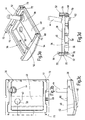
- a special feature of the invention is that the fuel tank 36 for the fuel supply of the drive motor at the same time as ground cover in the shape of a double-walled floor pan with a over a filler neck 44 accessible cavity 46 adapted to receive fuel is.
- the fuel tank 36 has at its upper, trough-shaped Boundary wall 38 a trough 40, which at its lowest point 42 in a closable with a lid 45, the cavity 46 penetrating Outflow channel 50 opens.
- the fuel tank 36 also has raised double-walled side edges 52, the outer surfaces 54 than with adjacent Body parts are aligned side panels are formed.
- Of the Filler 44 is on the upper trough-shaped boundary wall 38th molded and engages in a free part of the engine compartment.
- One of the connecting pieces 66 is designed as a suction nozzle, at the inside of the cavity 46 a reaching to the tank bottom, not shown suction pipe is connected, while the other Connecting piece 66 is formed as a return pipe, on the circulating Fuel is returned to the fuel tank 36.
- the fuel tank 36 designed as a bottom trough forms a closed one Ground cover and thus ensures an effective seal in the bottom area against noise emissions from the engine compartment. Anything from the Engine or the units located on the engine leaking fluids or parts are trapped in the trough and can pass through the drainage channel 50 be lowered down specifically.
- the invention relates to a mobile construction machine, for example a mortar spraying machine or a compressed air generator.
- the construction machine has one in an engine compartment 32 arranged drive motor with an engine compartment 32 down to the end, on a chassis 10 fixable bottom cover and with a formed as a plastic molding fuel tank 36.
- the fuel tank 36 has a multiple function. He is at the same time designed as a ground cover and has for this purpose the Shape of the engine compartment 32 down final double-walled Floor pan with a via a filler neck 44 accessible cavity 46 for receiving fuel.
Landscapes
- Engineering & Computer Science (AREA)
- Mechanical Engineering (AREA)
- Architecture (AREA)
- Chemical & Material Sciences (AREA)
- Combustion & Propulsion (AREA)
- Transportation (AREA)
- Structural Engineering (AREA)
- Sustainable Development (AREA)
- Sustainable Energy (AREA)
- Life Sciences & Earth Sciences (AREA)
- Civil Engineering (AREA)
- Cooling, Air Intake And Gas Exhaust, And Fuel Tank Arrangements In Propulsion Units (AREA)
- Body Structure For Vehicles (AREA)
- Filling Or Discharging Of Gas Storage Vessels (AREA)
Abstract
Description
- Fig. 1
- eine Mörtelspritzmaschine in schaubildlicher Darstellung;
- Fig. 2
- eine Untenansicht der Mörtelspritzmaschine in schaubildlicher Darstellung;
- Fig. 3a bis 3d
- den Kraftstofftank der Mörtelspritzmaschine nach Fig. 1 und Fig. 2 in schaubildlicher Darstellung, in Draufsicht und in zwei Seitenansichten.
Claims (12)
- Mobile Baumaschine, insbesondere Mörtelspritzmaschine oder Drucklufterzeuger, mit einem in einem Motorraum (32) angeordneten Antriebsmotor, mit einer den Antriebsmotor nach unten abschließenden, an einem Fahrgestell (10) fixierten Bodenabdeckung und mit einem als Kunststoff-Formteil ausgebildeten Kraftstofftank (36), dadurch gekennzeichnet, dass der Kraftstofftank (36) zugleich die Bodenabdeckung bildet.
- Mobile Baumaschine nach Anspruch 1, dadurch gekennzeichnet, dass der Kraftstofftank (36) die Gestalt einer den Motorraum (32) nach unten abschließenden doppelwandigen Bodenwanne mit einem über einen Einfüllstutzen (44) zugänglichen Hohlraum (46) zur Aufnahme von Kraftstoff aufweist.
- Mobile Baumaschine nach Anspruch 1 oder 2, dadurch gekennzeichnet, dass der Kraftstofftank (36) an seiner oberen wannenförmigen Begrenzungswand (38) eine Mulde (40) aufweist, die an ihrer tiefsten Stelle (42) in einen mit einem Deckel (45) verschließbaren, den Hohlraum (46) durchdringenden Abflusskanal (50) mündet.
- Mobile Baumaschine nach einem der Ansprüche 1 bis 3, dadurch gekennzeichnet, dass der Kraftstofftank (36) hochgezogene doppelwandige Seitenränder (52) aufweist, deren Außenflächen (54) als mit benachbarten Karosserieteilen (30) fluchtende Seitenblenden ausgebildet sind.
- Mobile Baumaschine nach einem der Ansprüche 1 bis 4, dadurch gekennzeichnet, dass der Einfüllstutzen (44) an der oberen wannenförmigen Begrenzungswand (38) angeformt ist und nach oben in einen freien Teil des Motorraums (32) eingreift.
- Mobile Baumaschine nach einem der Ansprüche 1 bis 5, dadurch gekennzeichnet, dass an der unteren Begrenzungswand (56) nach unten überstehende, vorzugsweise hohl ausgebildete Verstärkungsrippen (58) angeformt sind.
- Mobile Baumaschine nach Anspruch 6, dadurch gekennzeichnet, dass durch die Verstärkungsrippen (58, 68) zugleich Lüftungskanäle (60) begrenzt sind.
- Mobile Baumaschine nach einem der Ansprüche 1 bis 7, dadurch gekennzeichnet, dass die seitlichen Wannenränder (52) nach unten überstehende, über die gesamte Länge der Bodenwanne sich erstreckende Randrippen (68) aufweisen.
- Mobile Baumaschine nach Anspruch 8, dadurch gekennzeichnet, dass an der Unterkante der Randrippen (58) jeweils eine Längsnut (70) eingeformt ist, in die ein am Fahrgestell (10) fixierter Metallbügel (74) eingreift.
- Mobile Baumaschine nach Anspruch 9, dadurch gekennzeichnet, dass die Längsnuten (70) über die endseitigen Begrenzungskanten (73) der Randrippen (68) nach oben verlängert sind, und dass die Metallbügel (74) mit abgebogenen Enden in die nach oben weisenden Verlängerungen (72) eingreifen.
- Mobile Baumaschine nach Anspruch 8 oder 9, dadurch gekennzeichnet, dass die Metallbügel (74) an ihren Enden eine durch eine fahrgestellfeste Öffnung hindurchsteckbare Gewindepartie zur Aufnahme einer Befestigungsmutter aufweisen.
- Mobile Baumaschine nach einem der Ansprüche 1 bis 11, dadurch gekennzeichnet, dass an den Oberkanten der Randrippen (68) zwei Anschlussstutzen (66) angeordnet sind, von welchen mindestens einer im Hohlrauminneren mit einem bis zum Hohlraumboden führenden Saugrohr verbunden ist.
Applications Claiming Priority (2)
| Application Number | Priority Date | Filing Date | Title |
|---|---|---|---|
| DE10351279 | 2003-10-31 | ||
| DE10351279A DE10351279A1 (de) | 2003-10-31 | 2003-10-31 | Mobile Baumaschine mit Motorantrieb und Kraftstofftank |
Publications (2)
| Publication Number | Publication Date |
|---|---|
| EP1528184A1 true EP1528184A1 (de) | 2005-05-04 |
| EP1528184B1 EP1528184B1 (de) | 2006-06-07 |
Family
ID=34399662
Family Applications (1)
| Application Number | Title | Priority Date | Filing Date |
|---|---|---|---|
| EP04025464A Expired - Lifetime EP1528184B1 (de) | 2003-10-31 | 2004-10-27 | Mobile Baumaschine mit Motorantrieb und Kraftstofftank |
Country Status (5)
| Country | Link |
|---|---|
| EP (1) | EP1528184B1 (de) |
| AT (1) | ATE329100T1 (de) |
| DE (2) | DE10351279A1 (de) |
| ES (1) | ES2265134T3 (de) |
| PT (1) | PT1528184E (de) |
Cited By (2)
| Publication number | Priority date | Publication date | Assignee | Title |
|---|---|---|---|---|
| WO2014166770A1 (de) * | 2013-04-12 | 2014-10-16 | Putzmeister Mörtelmaschinen GmbH | Misch- und fördergerät mit hydraulikaggregat |
| EP2878817A1 (de) * | 2013-11-27 | 2015-06-03 | BMS Bau-Maschinen-Service AG | Mörtelpumpe |
Families Citing this family (2)
| Publication number | Priority date | Publication date | Assignee | Title |
|---|---|---|---|---|
| CN112593687B (zh) * | 2021-01-14 | 2022-04-08 | 义乌市昕闵日用品有限公司 | 一种用于地面刷漆的刷漆车 |
| DE112022003356T5 (de) | 2021-09-08 | 2024-06-20 | Yachiyo Industry Co., Ltd. | Kraftstofftank |
Citations (5)
| Publication number | Priority date | Publication date | Assignee | Title |
|---|---|---|---|---|
| US3881706A (en) * | 1973-06-28 | 1975-05-06 | William C Mohrmann | Trailer having concrete mixer thereon |
| EP0482930A2 (de) * | 1990-10-24 | 1992-04-29 | Baker Hughes Incorporated | Mischapparat |
| US5433520A (en) * | 1993-12-13 | 1995-07-18 | Michigan Ash Sales Company | Method and apparatus for continuously processing particulate cementitious material and fly ash solids and mixing them with a liquid to provide a liquid slurry of consistent proportions |
| US20030002384A1 (en) * | 2000-04-05 | 2003-01-02 | Jeffrey Flood | Portable concrete plant |
| US20030085299A1 (en) * | 2001-03-23 | 2003-05-08 | Schacht Mark W | Self-contained finish spraying apparatus |
Family Cites Families (8)
| Publication number | Priority date | Publication date | Assignee | Title |
|---|---|---|---|---|
| DE3611455A1 (de) * | 1986-04-05 | 1987-10-08 | Rolf Mayer | Hydraulisch steuerbares, fahrbares arbeitsgeraet, insbesondere bagger |
| DE8904166U1 (de) * | 1989-04-04 | 1989-05-18 | Still Gmbh, 2000 Hamburg | Gabelstapler |
| FR2671321A1 (fr) * | 1991-01-08 | 1992-07-10 | Renault | Structure assemblee de plancher pour vehicules automobiles avec reservoir de combustible integre. |
| DE9317321U1 (de) * | 1993-11-15 | 1994-02-03 | Rotzler GmbH + Co Spezialfabrik für Seilwinden und Hebezeuge, 79585 Steinen | Mehrzweck-Fahrzeug |
| DE19741314A1 (de) * | 1997-09-19 | 1999-03-25 | Bayerische Motoren Werke Ag | Kraftstoffversorgungsanlage für ein Kraftfahrzeug |
| DE29804856U1 (de) * | 1998-03-18 | 1998-07-09 | Karl Schaeff GmbH & Co. Maschinenfabrik, 74595 Langenburg | Bagger, insbesondere Minibagger |
| DE10013079A1 (de) * | 2000-03-17 | 2001-09-20 | Still Gmbh | Mobile Arbeitsmaschine |
| DE10054876C2 (de) * | 2000-11-06 | 2002-11-07 | Sig Kautex Gmbh & Co Kg | Doppelwandiger Kraftstoffbehälter aus Kunststoff |
-
2003
- 2003-10-31 DE DE10351279A patent/DE10351279A1/de not_active Withdrawn
-
2004
- 2004-10-27 ES ES04025464T patent/ES2265134T3/es not_active Expired - Lifetime
- 2004-10-27 AT AT04025464T patent/ATE329100T1/de not_active IP Right Cessation
- 2004-10-27 PT PT04025464T patent/PT1528184E/pt unknown
- 2004-10-27 DE DE502004000701T patent/DE502004000701D1/de not_active Expired - Lifetime
- 2004-10-27 EP EP04025464A patent/EP1528184B1/de not_active Expired - Lifetime
Patent Citations (5)
| Publication number | Priority date | Publication date | Assignee | Title |
|---|---|---|---|---|
| US3881706A (en) * | 1973-06-28 | 1975-05-06 | William C Mohrmann | Trailer having concrete mixer thereon |
| EP0482930A2 (de) * | 1990-10-24 | 1992-04-29 | Baker Hughes Incorporated | Mischapparat |
| US5433520A (en) * | 1993-12-13 | 1995-07-18 | Michigan Ash Sales Company | Method and apparatus for continuously processing particulate cementitious material and fly ash solids and mixing them with a liquid to provide a liquid slurry of consistent proportions |
| US20030002384A1 (en) * | 2000-04-05 | 2003-01-02 | Jeffrey Flood | Portable concrete plant |
| US20030085299A1 (en) * | 2001-03-23 | 2003-05-08 | Schacht Mark W | Self-contained finish spraying apparatus |
Cited By (3)
| Publication number | Priority date | Publication date | Assignee | Title |
|---|---|---|---|---|
| WO2014166770A1 (de) * | 2013-04-12 | 2014-10-16 | Putzmeister Mörtelmaschinen GmbH | Misch- und fördergerät mit hydraulikaggregat |
| DE102013206592B4 (de) | 2013-04-12 | 2025-05-28 | Putzmeister Mörtelmaschinen GmbH | Misch- und Fördergerät mit Hydraulikaggregat |
| EP2878817A1 (de) * | 2013-11-27 | 2015-06-03 | BMS Bau-Maschinen-Service AG | Mörtelpumpe |
Also Published As
| Publication number | Publication date |
|---|---|
| DE10351279A1 (de) | 2005-06-02 |
| PT1528184E (pt) | 2006-09-29 |
| ES2265134T3 (es) | 2007-02-01 |
| DE502004000701D1 (de) | 2006-07-20 |
| ATE329100T1 (de) | 2006-06-15 |
| EP1528184B1 (de) | 2006-06-07 |
Similar Documents
| Publication | Publication Date | Title |
|---|---|---|
| DE19959557B4 (de) | Blasgerät | |
| DE19543350C1 (de) | Aggregateträger für eine Brennkraftmaschine | |
| EP1830071B1 (de) | Kunstoffverdichtergehäuse | |
| DE4401186A1 (de) | Schneidmaschine | |
| DE2620774A1 (de) | Kraftfahrzeug mit schalldaemmend verkleidetem motor | |
| DE7714617U1 (de) | Omnibus-Klimaanlage | |
| DE102011115792A1 (de) | Anordnung mit Wasserkasten und Wasserablauf für ein Kraftfahrzeug | |
| DE2649043A1 (de) | Kompressoraggregat | |
| EP3359309B1 (de) | Luftgekühltes hochdruckreinigungsgerät | |
| DE112012003486T5 (de) | Kraftstoffversorgungssystem und Siphonschutz-Strahlpumpe | |
| DE202007003326U1 (de) | Straßenfertiger | |
| EP3490881A1 (de) | Aufblasbares sportgerät, vorzugsweise für den wassersport | |
| DE102015107708A1 (de) | Lufteinlass eines Klimatisierungssystems eines Kraftfahrzeugs | |
| DE4427738A1 (de) | Arbeitsgerät mit einem Verbrennungsmotor | |
| EP1528184B1 (de) | Mobile Baumaschine mit Motorantrieb und Kraftstofftank | |
| DE10302191A1 (de) | Akustisch wirksame Ölwanne | |
| DE10028985A1 (de) | Kraftstoff-Förder- und Lüftungssystem | |
| DE102006058070A1 (de) | Arbeitsmaschine mit Traggestell und Abdeckhaube | |
| DE102005045292A1 (de) | Entwässerungsanordnung für einen Hohlraum einer Kraftwagenkarosserie | |
| DE10061013B4 (de) | Fördereinrichtung für ein Kraftfahrzeug und Vorratsbehälter für eine Fördereinrichtung | |
| DE3630435A1 (de) | Fahrzeugfront mit wenigstens einer lufteintrittsoeffnung auf jeder seite | |
| DE19545979A1 (de) | Luftansaugfilter-Einrichtung für einen Kraftfahrzeugmotor | |
| EP0284727B1 (de) | Ölbehälter | |
| DE102007028185A1 (de) | Versorgungseinheit mit einem Motor-Generator-Aggregat als Stromerzeuger | |
| DE19644464B4 (de) | Kraftstoffbehälter für ein Kraftfahrzeug |
Legal Events
| Date | Code | Title | Description |
|---|---|---|---|
| PUAI | Public reference made under article 153(3) epc to a published international application that has entered the european phase |
Free format text: ORIGINAL CODE: 0009012 |
|
| AK | Designated contracting states |
Kind code of ref document: A1 Designated state(s): AT BE BG CH CY CZ DE DK EE ES FI FR GB GR HU IE IT LI LU MC NL PL PT RO SE SI SK TR |
|
| AX | Request for extension of the european patent |
Extension state: AL HR LT LV MK |
|
| 17P | Request for examination filed |
Effective date: 20050319 |
|
| GRAP | Despatch of communication of intention to grant a patent |
Free format text: ORIGINAL CODE: EPIDOSNIGR1 |
|
| AKX | Designation fees paid |
Designated state(s): AT BE BG CH CY CZ DE DK EE ES FI FR GB GR HU IE IT LI LU MC NL PL PT RO SE SI SK TR |
|
| GRAS | Grant fee paid |
Free format text: ORIGINAL CODE: EPIDOSNIGR3 |
|
| GRAA | (expected) grant |
Free format text: ORIGINAL CODE: 0009210 |
|
| AK | Designated contracting states |
Kind code of ref document: B1 Designated state(s): AT BE BG CH CY CZ DE DK EE ES FI FR GB GR HU IE IT LI LU MC NL PL PT RO SE SI SK TR |
|
| PG25 | Lapsed in a contracting state [announced via postgrant information from national office to epo] |
Ref country code: IT Free format text: LAPSE BECAUSE OF FAILURE TO SUBMIT A TRANSLATION OF THE DESCRIPTION OR TO PAY THE FEE WITHIN THE PRESCRIBED TIME-LIMIT;WARNING: LAPSES OF ITALIAN PATENTS WITH EFFECTIVE DATE BEFORE 2007 MAY HAVE OCCURRED AT ANY TIME BEFORE 2007. THE CORRECT EFFECTIVE DATE MAY BE DIFFERENT FROM THE ONE RECORDED. Effective date: 20060607 Ref country code: CZ Free format text: LAPSE BECAUSE OF FAILURE TO SUBMIT A TRANSLATION OF THE DESCRIPTION OR TO PAY THE FEE WITHIN THE PRESCRIBED TIME-LIMIT Effective date: 20060607 Ref country code: SK Free format text: LAPSE BECAUSE OF FAILURE TO SUBMIT A TRANSLATION OF THE DESCRIPTION OR TO PAY THE FEE WITHIN THE PRESCRIBED TIME-LIMIT Effective date: 20060607 Ref country code: FI Free format text: LAPSE BECAUSE OF FAILURE TO SUBMIT A TRANSLATION OF THE DESCRIPTION OR TO PAY THE FEE WITHIN THE PRESCRIBED TIME-LIMIT Effective date: 20060607 Ref country code: RO Free format text: LAPSE BECAUSE OF FAILURE TO SUBMIT A TRANSLATION OF THE DESCRIPTION OR TO PAY THE FEE WITHIN THE PRESCRIBED TIME-LIMIT Effective date: 20060607 Ref country code: PL Free format text: LAPSE BECAUSE OF FAILURE TO SUBMIT A TRANSLATION OF THE DESCRIPTION OR TO PAY THE FEE WITHIN THE PRESCRIBED TIME-LIMIT Effective date: 20060607 Ref country code: SI Free format text: LAPSE BECAUSE OF FAILURE TO SUBMIT A TRANSLATION OF THE DESCRIPTION OR TO PAY THE FEE WITHIN THE PRESCRIBED TIME-LIMIT Effective date: 20060607 |
|
| REG | Reference to a national code |
Ref country code: GB Ref legal event code: FG4D Free format text: NOT ENGLISH |
|
| REG | Reference to a national code |
Ref country code: CH Ref legal event code: EP |
|
| REG | Reference to a national code |
Ref country code: IE Ref legal event code: FG4D Free format text: LANGUAGE OF EP DOCUMENT: GERMAN |
|
| REF | Corresponds to: |
Ref document number: 502004000701 Country of ref document: DE Date of ref document: 20060720 Kind code of ref document: P |
|
| GBT | Gb: translation of ep patent filed (gb section 77(6)(a)/1977) |
Effective date: 20060725 |
|
| PG25 | Lapsed in a contracting state [announced via postgrant information from national office to epo] |
Ref country code: DK Free format text: LAPSE BECAUSE OF FAILURE TO SUBMIT A TRANSLATION OF THE DESCRIPTION OR TO PAY THE FEE WITHIN THE PRESCRIBED TIME-LIMIT Effective date: 20060907 Ref country code: SE Free format text: LAPSE BECAUSE OF FAILURE TO SUBMIT A TRANSLATION OF THE DESCRIPTION OR TO PAY THE FEE WITHIN THE PRESCRIBED TIME-LIMIT Effective date: 20060907 |
|
| REG | Reference to a national code |
Ref country code: PT Ref legal event code: SC4A Effective date: 20060811 |
|
| PG25 | Lapsed in a contracting state [announced via postgrant information from national office to epo] |
Ref country code: MC Free format text: LAPSE BECAUSE OF NON-PAYMENT OF DUE FEES Effective date: 20061031 |
|
| ET | Fr: translation filed | ||
| REG | Reference to a national code |
Ref country code: ES Ref legal event code: FG2A Ref document number: 2265134 Country of ref document: ES Kind code of ref document: T3 |
|
| PLBE | No opposition filed within time limit |
Free format text: ORIGINAL CODE: 0009261 |
|
| STAA | Information on the status of an ep patent application or granted ep patent |
Free format text: STATUS: NO OPPOSITION FILED WITHIN TIME LIMIT |
|
| 26N | No opposition filed |
Effective date: 20070308 |
|
| PG25 | Lapsed in a contracting state [announced via postgrant information from national office to epo] |
Ref country code: GR Free format text: LAPSE BECAUSE OF FAILURE TO SUBMIT A TRANSLATION OF THE DESCRIPTION OR TO PAY THE FEE WITHIN THE PRESCRIBED TIME-LIMIT Effective date: 20060908 |
|
| PG25 | Lapsed in a contracting state [announced via postgrant information from national office to epo] |
Ref country code: EE Free format text: LAPSE BECAUSE OF FAILURE TO SUBMIT A TRANSLATION OF THE DESCRIPTION OR TO PAY THE FEE WITHIN THE PRESCRIBED TIME-LIMIT Effective date: 20060607 Ref country code: BG Free format text: LAPSE BECAUSE OF FAILURE TO SUBMIT A TRANSLATION OF THE DESCRIPTION OR TO PAY THE FEE WITHIN THE PRESCRIBED TIME-LIMIT Effective date: 20060907 |
|
| PG25 | Lapsed in a contracting state [announced via postgrant information from national office to epo] |
Ref country code: HU Free format text: LAPSE BECAUSE OF FAILURE TO SUBMIT A TRANSLATION OF THE DESCRIPTION OR TO PAY THE FEE WITHIN THE PRESCRIBED TIME-LIMIT Effective date: 20061208 Ref country code: LU Free format text: LAPSE BECAUSE OF NON-PAYMENT OF DUE FEES Effective date: 20061027 |
|
| PG25 | Lapsed in a contracting state [announced via postgrant information from national office to epo] |
Ref country code: CY Free format text: LAPSE BECAUSE OF FAILURE TO SUBMIT A TRANSLATION OF THE DESCRIPTION OR TO PAY THE FEE WITHIN THE PRESCRIBED TIME-LIMIT Effective date: 20060607 |
|
| PGFP | Annual fee paid to national office [announced via postgrant information from national office to epo] |
Ref country code: TR Payment date: 20090924 Year of fee payment: 6 |
|
| PGFP | Annual fee paid to national office [announced via postgrant information from national office to epo] |
Ref country code: AT Payment date: 20091015 Year of fee payment: 6 Ref country code: CH Payment date: 20091026 Year of fee payment: 6 Ref country code: DE Payment date: 20091028 Year of fee payment: 6 Ref country code: ES Payment date: 20091028 Year of fee payment: 6 Ref country code: IE Payment date: 20091028 Year of fee payment: 6 |
|
| PGFP | Annual fee paid to national office [announced via postgrant information from national office to epo] |
Ref country code: NL Payment date: 20091016 Year of fee payment: 6 |
|
| PGFP | Annual fee paid to national office [announced via postgrant information from national office to epo] |
Ref country code: PT Payment date: 20091016 Year of fee payment: 6 |
|
| PGFP | Annual fee paid to national office [announced via postgrant information from national office to epo] |
Ref country code: FR Payment date: 20091110 Year of fee payment: 6 Ref country code: GB Payment date: 20091022 Year of fee payment: 6 Ref country code: IT Payment date: 20091027 Year of fee payment: 6 |
|
| PGFP | Annual fee paid to national office [announced via postgrant information from national office to epo] |
Ref country code: BE Payment date: 20091130 Year of fee payment: 6 |
|
| BERE | Be: lapsed |
Owner name: *PUTZMEISTER MORTELMASCHINEN G.M.B.H. Effective date: 20101031 |
|
| REG | Reference to a national code |
Ref country code: PT Ref legal event code: MM4A Free format text: LAPSE DUE TO NON-PAYMENT OF FEES Effective date: 20110427 |
|
| REG | Reference to a national code |
Ref country code: NL Ref legal event code: V1 Effective date: 20110501 |
|
| REG | Reference to a national code |
Ref country code: CH Ref legal event code: PL |
|
| GBPC | Gb: european patent ceased through non-payment of renewal fee |
Effective date: 20101027 |
|
| PG25 | Lapsed in a contracting state [announced via postgrant information from national office to epo] |
Ref country code: FR Free format text: LAPSE BECAUSE OF NON-PAYMENT OF DUE FEES Effective date: 20101102 Ref country code: CH Free format text: LAPSE BECAUSE OF NON-PAYMENT OF DUE FEES Effective date: 20101031 Ref country code: PT Free format text: LAPSE BECAUSE OF NON-PAYMENT OF DUE FEES Effective date: 20110427 Ref country code: LI Free format text: LAPSE BECAUSE OF NON-PAYMENT OF DUE FEES Effective date: 20101031 |
|
| REG | Reference to a national code |
Ref country code: FR Ref legal event code: ST Effective date: 20110630 |
|
| PG25 | Lapsed in a contracting state [announced via postgrant information from national office to epo] |
Ref country code: GB Free format text: LAPSE BECAUSE OF NON-PAYMENT OF DUE FEES Effective date: 20101027 Ref country code: AT Free format text: LAPSE BECAUSE OF NON-PAYMENT OF DUE FEES Effective date: 20101027 Ref country code: BE Free format text: LAPSE BECAUSE OF NON-PAYMENT OF DUE FEES Effective date: 20101031 Ref country code: NL Free format text: LAPSE BECAUSE OF NON-PAYMENT OF DUE FEES Effective date: 20110501 |
|
| REG | Reference to a national code |
Ref country code: DE Ref legal event code: R119 Ref document number: 502004000701 Country of ref document: DE Effective date: 20110502 |
|
| PG25 | Lapsed in a contracting state [announced via postgrant information from national office to epo] |
Ref country code: IE Free format text: LAPSE BECAUSE OF NON-PAYMENT OF DUE FEES Effective date: 20101027 |
|
| REG | Reference to a national code |
Ref country code: ES Ref legal event code: FD2A Effective date: 20111118 |
|
| PG25 | Lapsed in a contracting state [announced via postgrant information from national office to epo] |
Ref country code: IT Free format text: LAPSE BECAUSE OF NON-PAYMENT OF DUE FEES Effective date: 20101027 |
|
| PG25 | Lapsed in a contracting state [announced via postgrant information from national office to epo] |
Ref country code: ES Free format text: LAPSE BECAUSE OF NON-PAYMENT OF DUE FEES Effective date: 20101028 |
|
| PG25 | Lapsed in a contracting state [announced via postgrant information from national office to epo] |
Ref country code: TR Free format text: LAPSE BECAUSE OF NON-PAYMENT OF DUE FEES Effective date: 20101027 |
|
| PG25 | Lapsed in a contracting state [announced via postgrant information from national office to epo] |
Ref country code: DE Free format text: LAPSE BECAUSE OF NON-PAYMENT OF DUE FEES Effective date: 20110502 |