EP1528327A2 - appareil cuisinier - Google Patents
appareil cuisinier Download PDFInfo
- Publication number
- EP1528327A2 EP1528327A2 EP04014793A EP04014793A EP1528327A2 EP 1528327 A2 EP1528327 A2 EP 1528327A2 EP 04014793 A EP04014793 A EP 04014793A EP 04014793 A EP04014793 A EP 04014793A EP 1528327 A2 EP1528327 A2 EP 1528327A2
- Authority
- EP
- European Patent Office
- Prior art keywords
- cooking
- cooking appliance
- state
- appliance according
- field
- Prior art date
- Legal status (The legal status is an assumption and is not a legal conclusion. Google has not performed a legal analysis and makes no representation as to the accuracy of the status listed.)
- Withdrawn
Links
Images

Classifications
-
- F—MECHANICAL ENGINEERING; LIGHTING; HEATING; WEAPONS; BLASTING
- F24—HEATING; RANGES; VENTILATING
- F24C—DOMESTIC STOVES OR RANGES ; DETAILS OF DOMESTIC STOVES OR RANGES, OF GENERAL APPLICATION
- F24C15/00—Details
- F24C15/20—Removing cooking fumes
- F24C15/2042—Devices for removing cooking fumes structurally associated with a cooking range e.g. downdraft
-
- F—MECHANICAL ENGINEERING; LIGHTING; HEATING; WEAPONS; BLASTING
- F24—HEATING; RANGES; VENTILATING
- F24C—DOMESTIC STOVES OR RANGES ; DETAILS OF DOMESTIC STOVES OR RANGES, OF GENERAL APPLICATION
- F24C7/00—Stoves or ranges heated by electric energy
- F24C7/10—Stoves or ranges heated by electric energy with special adaptation for travelling, e.g. collapsible
-
- F—MECHANICAL ENGINEERING; LIGHTING; HEATING; WEAPONS; BLASTING
- F24—HEATING; RANGES; VENTILATING
- F24C—DOMESTIC STOVES OR RANGES ; DETAILS OF DOMESTIC STOVES OR RANGES, OF GENERAL APPLICATION
- F24C15/00—Details
- F24C15/30—Arrangements for mounting stoves or ranges in particular locations
Definitions
- the invention relates to a cooking appliance, the at least one Garfeld with at least one cooking zone includes.
- Cooking method for example, cooking, roasting or Grilling.
- cooking appliances used for the execution of this cooking process.
- the underlying the cooking appliances Technique is usually based on the conventional thermal Heating with gas or electrical energy, on microwave radiation and on induction.
- the Cooking process are in the cooking appliances corresponding cooking areas, in particular Garfelder or cooking chambers formed.
- Cooking appliances are usually set up as stand-alone appliances or integrated in kitchenettes. Your space requirement is pretty big. This is usually not a problem if there is enough space in kitchens. Different On the other hand, in smaller apartments, one-room apartments, termetenneckn, offices, etc. off. There is often There is not enough space for common cooking appliances or setting up a cooking appliance would be the remaining Space too tight.
- EP 0 873 669 B1 discloses a compact design for a cooking appliance.
- This cooking appliance has cooking zones on top and bottom on, with each the upward facing Garzonen can be used. Furthermore, this cooking appliance is not firmly integrated into a kitchenette, rather it may be due to Its compact dimensions in a designated Tray kept and set up for operation only become.
- the disadvantage here however, that the device for the operation specially brought out of his compartment and possibly still needs to be connected.
- a suitable Storage area with corresponding electrical connection options be present and cleared.
- the invention is therefore the object of a cooking appliance indicate that solves the space problems mentioned above, flexible and mobile in different places can be used and eliminates haze and steam produced during cooking. Further the cooking appliance should be designed such that the Room then, if the cooking appliance is not used, too without clearing the device the above-mentioned kitchen character no longer has.
- the advantage achieved by the invention is in particular in that the cooking appliance in addition to an operating condition also can take a rest and / or transport state and thus easy to transport and thus mobile and is flexible.
- Another advantage exists in that the cooking appliance comprises a trigger device and therefore always a deduction for each site for Haze and steam is present and thus the emergence of Odors can be prevented or at least reduced.
- the cooking appliance according to the invention claimed in peace and / or Transport state significantly less space than in the operating state, especially in small apartments, apartments, Offices or small rooms is beneficial.
- the cooking appliance in the first state a more compact, especially flatter, outer shape than in second state, in particular in at least one spatial dimension in the first state smaller dimensions, preferably by at least the factor 4 smaller dimensions than in the second state.
- the Gärfeld in the second Condition a width of 60 to 100 cm, in particular of 80 to 90 cm, and a depth of 20 to 60 cm, in particular from 35 to 45 cm, and the trigger unit in the second Condition is located about 50 to 70 cm above the cooking field, and the cooking appliance in the first state has a depth of at most 10 cm, in particular of the highest 8 cm.
- the advantage of this design and these dimensions of the Cooking appliance is particularly in the small footprint of the Device, especially in the first resting and / or transport state.
- the Garfeld and / or the trigger device hinged or pivotally connected to the support element are such that the Garfeld and / or the trigger device in the first state a first folding position and in second state take a second folding position.
- first and second folding position of the cooking field and / or the discharge device substantially a 90 ° angle lock in.
- the hinged connection between Garfeld and carrier element and / or take-off device and carrier element is formed by at least one hinge.
- At least one locking device is provided with the cooking field and / or the extraction device in at least one predetermined position, in particular in the first and / or second folding position, can be locked or locked.
- Such a lock ensures that the given Folding positions are taken safely and stably. This is especially in the unfolded second folding position of the Garfelds of particular importance, since in this Operating state considerable loads, such as pots, Pans and the food itself, arranged on the cooking field become.
- the lock must ensure that the cooking field not tilted even under heavy load, but stable maintains its position.
- a further advantageous embodiment provides that the Transition from the second to the first folding position of the cooking field only when falling below a predetermined temperature the Garzonen is possible. This will prevent a to hot plate is folded and thereby the support element and / or the trigger device is damaged. This can of course also by a corresponding Heat-resistant training of support element and / or trigger device be prevented.
- the cooking appliance according to the invention provides that the cooking appliance for attachment to and / or at least partially Integration in a substantially vertical wall, in particular a house and / or room wall, is formed.
- This embodiment is particularly space-saving and therefore especially for small apartments, apartments or Offices suitable.
- Another application is the supplement to conventional cooking appliances in kitchens. That saves space attachable cooking device according to the invention can be used here as Supplementary device rarely needed cooking techniques or cooking process keep ready or additional cooking zones at strong Provide kitchen utilization.
- the wall mounting of the cooking appliance can take place in that the carrier element of the cooking appliance for the attachment of the cooking appliance and / or for at least partial integration the cooking appliance is formed in the wall.
- the carrier element comprises a carrier plate, when mounting the cooking appliance on the wall substantially oriented parallel to the wall.
- the wall mounting of the cooking appliance can by at least one Be screwed or be prepared. alternative or additively, the wall mounting is also by at least a wall hook, hung in the cooking appliance and / or can be hung, manufactured or manufactured.
- one of the first side of the Garfeld's opposite side of the Garfelds and / or one of the first side of the discharge device opposite lying second side of the trigger device colored is designed and / or decorated and / or decorable is trained.
- the Garfeld In the first state (resting and / or transport state) hangs the cooking appliance like a picture on a wall. A viewer sees of the cooking appliance especially him in the first state facing second sides of Garfeld and trigger device.
- the Garfeld By appropriate design, i. coloring or decoration, the Garfeld is therefore in the first state to a decorative wall object. The design can do this be targeted conspicuous designed.
- a corresponding decor but also an adaptation to more arranged in the room furniture, such as a Kitchenette, possible.
- the wall mounting takes place such that the height of the cooking zones of the cooking field above one below the Cooking appliance floor in the second state (operating state) between 50 cm and 130 cm, preferably between 80 cm and 110 cm.
- the wall bracket is adjustable, in such a way that the height of the Garzonen in the second state to the height a user is customizable to allow for the user to enable an ergonomically correct working posture.
- a particularly preferred and advantageous embodiment of the cooking appliance according to the invention provides that the Garfeld at or near a lower end of the support member on the support member is attached and / or the trigger on the or near an upper end of the support member on the support member is appropriate.
- the Garfeld and withdrawal device folded against the support element and the cooking appliance hangs flat on the picture like a picture Wall.
- this allows Embodiment the greatest possible distance between Garfeld and extractor and thus an easily accessible Working area above the cooking area.
- the transition from the first to second folding position and / or from the second to the first Folding position of the cooking field and / or the trigger device manually and / or by gravity and / or electrically and / or hydraulically and / or pneumatically.
- the Garfelds and / or the trigger device braked done and in particular provided braking elements are. This prevents, for example, the cooking field when unfolding "falls too fast after lower” and thereby the locking device, the carrier element and / or damaged itself.
- a switch in particular a touch and / or actuation-dependent switch, preferably one Overheating switch and / or a click switch and / or a Pressure switch and / or a push button, and / or by a sensor, in particular a touch and / or operation-dependent Sensor, is triggered.
- Overhub switch is a switch to understand against the first must be pressed to subsequently to allow a movement in the opposite direction. For example, it may be provided that the user of the cooking appliance in its idle state (first state) first against the Garfeld in the direction of one behind arranged support plate and thereby the pivoting or folding movement of the Garfelds away from the carrier plate triggered or enabled.
- a handle for the manual opening and / or closing of the cooking field and / or the withdrawal device is provided.
- the transition from the first to the second folding version of the Discharge device together with the transition from the first is triggered to the second folding position of the cooking field, in particular through a common switch and / or sensor, and / or the transition from the second to the first folding position the withdrawal device together with the transition from the second triggered to the first folding position of the cooking field is, in particular by a common switch and / or sensor.
- a further embodiment of the invention provides that in the second state of the cooking appliance, the cooking area and the extraction device essentially parallel to each other stand.
- the cooking area and the extraction device aligned substantially parallel to each other are such that they connect to each other and form complementary surfaces. This will make a visual created particularly appealing solution. Furthermore The available space is used optimally.
- the cooking appliance amounts the area ratio of the complementary areas of the cooking field and the discharge device about 2 to 1. Of course, however, any other area ratios possible.
- the arrangement may be such be designed that for the transition from the first to the second state first the Garfeld and then the Discharge device must be unfolded.
- the reverse arrangement is possible.
- the advantage of this arrangement lies in the fact that thereby the Garfeld and / or the Make extraction device with a greater depth and thereby, for example, on the Garfeld a larger area is available for the arrangement of the cooking zones.
- the height of the mounted on the wall cooking appliance in about the sum of Depth dimensions of Garfeld and extractor. at on the other hand, the alternative embodiment explained here The depth dimension of both the cooking field and the Discharge device almost equal to the height of the cooking appliance.
- Cooking appliance provides that in the first state of the cooking appliance the cooking field substantially parallel and the trigger device is oriented substantially perpendicular to the wall.
- Cooking appliance provides that the cooking field and / or the trigger device can be inserted into the carrier element, in particular completely insertable.
- the electrical connection of the cooking appliance can via a plug / socket coupling unit respectively. self-evident But it is also a fixed electrical installation possible.
- the operating mode for the discharge device can expediently a recirculation mode be provided. Especially in fixed installation of the cooking appliance but is also an exhaust air operation possible, the exhaust air to the outside or in one moved to another room.
- An expedient development also provides; that in or on the cooking appliance, in particular in or on the extraction device, a lighting is provided. This lighting can, for example, during the transition from the first in the second state will be turned on automatically and in the transition from the second to the first state automatically turned off.
- the operating and / or display elements for the Garfeld and / or the trigger device be integrated in a remote control for the cooking appliance.
- the carrier element at least predominantly from at least a heat-resistant material, in particular glass ceramic and / or stainless steel. This can damage be avoided due to heat.
- An expedient development of the cooking appliance provides that at least the cooking field and / or the carrier element a storage element is provided, in particular a glass plate or a wire mesh in the first state in the Cooking device inserted or retractable and / or retractable or folded and that can be pushed out in the second state or pushed out or unfolded or unfoldable is to provide the user with additional storage space.
- the cooking zones of the cooking appliance can be thermal heated cooking zones, in particular to cook, roast and / or Grill zones, and / or act around induction cooking zones. there all cooking zones can use the same technique but also different techniques used side by side become.
- the cooking field at least includes two Garzonen, in particular in their Diameter and / or in the cooking process provided by them differ.
- At least the first side of the cooking field in Essentially consists of glass ceramic.
- the extraction device may include a vent fan or air duct technology connected to a vent fan be. It can also be provided that the extraction device essentially an air guide element This is in particular essentially transparent Material, preferably made of Plexiglas or glass.
- At least two cooking fields and / or at least two extraction devices are provided, which can be opened and closed separately from one another and which in each case can be operated independently of one another in the unfolded state.
- a carrying handle may be provided on the cooking appliance with which the cooking appliance can be transported, in particular in the first state.
- a further development provides that the Garzonen of the Garfelds in the first state of the carrier element substantially be covered. As a result, the cooking zones are in the first state protected. In particular, during transport of the cooking appliance will damage the Garzonen by external action prevented.
- the cooking appliance Due to the mobility and flexibility of the cooking appliance can the cooking appliance can also be installed in areas where it is accessible to many people. It is therefore advantageous an anti-theft device, in particular a shut-off device, provided.
- An alternative or additive embodiment to the wall suspension of the cooking appliance according to the invention provides that the cooking appliance for resting on a base, in particular a worktop or a table; is trained.
- the cooking appliance can also be operated without wall mounting become.
- a frame in particular a mobile frame, attached or attachable.
- the device can also be used in places where there is no wall, be set up .
- this Frame can be folded to transport the cooking appliance and / or be designed removable from the cooking appliance.
- An advantageous embodiment of the cooking appliance provides that the cooking appliance, in particular the cooking field, easy to clean is designed. This makes the cooking appliance special user-friendly.
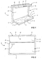
- FIG. 1 shows an embodiment of a cooking appliance 2 according to of the invention in a second state in a three-dimensional Presentation.
- a Garfeld 3 (often called cooktop) with a first page 4 (in FIG. 1 an upper side) and one of the first side 4 opposite second side 5 (bottom).
- At the first side 4 of the cooking field 3 are three Garzonen 6 and a Display and control panel 7 arranged for the cooking zone 2.
- Garzonen 6 all gardening techniques come into consideration, for example various types of thermal heating, but also induction heating.
- the cooking zones 6 all are equipped with identical technology, as well but also the provision of different techniques to the individual cooking zones 6 possible. Also the shape and the diameter of the individual Garzonen 6 can vary.
- the first page 4 of the cooking zone 3 consists in the illustrated Embodiment essentially of glass ceramic.
- the Glass ceramic is i.d.R. from a frame made of other materials, For example, stainless steel or plastic, edged (not shown in FIG. 1).
- the display and control panel 7 of the cooking zone 3, depending on the design of the operating and display elements also consist of glass ceramic (in this case, could be used to operate sensors below the glass ceramic can be arranged) or from another Material, such as plastic or metal.
- the cooking field 3 in FIG. 1 is configured flat, i. his Width and depth are significantly greater than its height. in the Interior of Garfelds 3 is at least partially for the Operation of the Garzonen 6 required technology housed (not shown).
- the Garfeld 3 shown in FIG 1 is hinged or pivotally mounted on a support member 8 near a lower End 9 of the support member 8 attached.
- the carrier element 8 comprises a rearwardly arranged carrier plate 10, which is encompassed by a support frame 11.
- ' is the Support frame 11 in the direction of the cooking field 3 with respect to the Support plate 10 before.
- the support plate 10 is at least An'der the user-facing side of a heat-resistant Material, such as stainless steel or glass ceramic.
- Near an upper end 12 of the support member 8 is also folding or pivoting a trigger device 13th appropriate.
- the extraction device 13 has a first side 14 (in FIG 1, a bottom) and one of the first side 14th Opposite second side 15 (top) on.
- the extraction device 14 in FIG. 1 is also flat, i.e. their width and depth. are significantly larger than their height.
- width and height correspond to the Discharge device 13 in about the width and height of Garfelds 3, the depth of the discharge device 13, however, is only about half as big as the depth of the cooking field 3.
- the deduction device 13 serves the deduction of the cooking resulting mist and steam. This can be, among other things Prevent the formation of disturbing odors or at least to reduce.
- a vent fan provided (not shown)
- the trigger the air and thus the vapor and steam is carried over the first page 14 (in FIG 1 bottom) of the trigger device 13.
- the blower including the engine and required electrical / electronic can in the interior of the discharge device 13th be arranged.
- the trigger device 13 only ventilation with one at another Place, for example, in or on the carrier element 8, arranged
- blower for example via air ducts (not shown).
- the extraction device 13 to an exhaust air installation connect the extracted air to the outside or in takes off another room.
- the trigger unit 13 of the cooking device 2 for a recirculation mode provided, i. the extracted air is cleaned and returned to the room.
- the deduction device 13 in FIG. 1 points to a user facing end face 16 a display and control panel 17 for controlling the functions of the discharge device 13th on.
- the cooking appliance 2 shown in FIG 1 is located in one second state, i. in an operating state.
- the cooking device 2 is ready for operation, i. Gar Vietnamesen and food can be placed on the Garzonen 6 and the food can be cooked. Evolving haze and steam can be sucked through the discharge device 13. in the second state close both the Garfeld 3 and the Discharge device 13 a 90 ° angle with the carrier plate 10 of the support member 8 a.
- the support plate 10 is vertical aligned, Garfeld 3 and extractor 13 are aligned horizontally and stand up with their first Pages 4, 14 parallel to each other.
- suitable Locking provided (not shown), which make sure that the cooking zone 3 and the triggering device 13 even under load, Garfeld 3 for example by cooking utensils we pots or pans and through the food to be cooked, to safely maintain its position.
- FIG 2 shows the embodiment of FIG 1 in the first Condition (rest and / or transport condition) in a frontal View.
- the cooking zone 3 and the discharge device 13 wherein the viewer in FIG 2, the second Page 5 of the cooking field 3 and the second side 15 of the trigger device 13 faces.
- the second page 5 of Garfelds 3 and the second side 15 of the discharge device 13th form a common area that only slightly through a separating strip between a narrow side 18 of the cooking field 3 and a narrow side 19 of the discharge device 13th is interrupted. From this common area takes the second side 5 of the cooking field 3 in the illustrated embodiment about 2/3 of the total area, the second page 15 the discharge device 13 about 1/3. Of course they are but also any other area divisions possible.
- the separating strip between Garfeld 3 and trigger device 13 not (as shown) horizontal and Straight line, rather, is also an oblique and / or a curved course possible.
- the second side 5 of the cooking field 3 and the second side 15 the trigger 13 may be colored. she but can also decoratively designed and with a corresponding Decor be or be provided. This can the cooking appliance visually to other room design elements, For example, other furniture or appliances, be adapted or be.
- Garfeld 3 and discharge device 13 are shown in FIG first state collapsed, i. against the carrier plate 10 panned.
- the support plate 10 is almost in FIG 2 completely covered by Garfeld 3 and deduction device 13.
- Garfeld 3 and discharge device 13 are parallel aligned with each other and parallel to the support plate 10, Furthermore, the narrow side 18 of the Garfeld 3 borders on the Narrow side 19 of the discharge device 13.
- a handle 20 for manual Unfold the cooking field 2 is provided.
- a sensor or switch whose operation is a motor-driven, electrical, hydraulic or pneumatic opening both the Garfelds 3 and the discharge device 13th triggers.
- a main switch is provided (not shown), which ensures that the cooking appliance is not operated in the first state can be, in particular, is switched off.
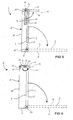
- FIG. 3 shows the embodiment of FIG 1 in the second State (operating state) in a side view
- FIG. 4 Embodiment according to FIG. 1 in the first state (rest and / or Transport state), also in a side view.
- the support frame 11 of the carrier element can be seen in each case 8, wherein the support frame 11, the support plate 10th hidden (shown in dashed lines). Furthermore, the cooking field 3 and the discharge device 13 shown.
- Garfeld 3 'and withdrawal device 13 take a unfolded state in which the first page 4 the Garfelds 3 and the first page 14 of the trigger device 13 facing each other in parallel. Good to see in FIG 3 also the 90 ° angle, both the Garfeld. 3 as well as the discharge device 13 with the support plate 10th lock in.
- Garfeld 3 and take-off device 13 take a collapsed state in which the first page 4 of Garfelds 3 and the first page 14 of the discharge device 13th lie parallel in a plane, which in turn parallel to Support plate 10 is oriented.
- the depth of the support frame 11 is formed such that it is the folded Garfeld 3 and the retracted extraction device 13 in the side view just covered.
- Hinges 21 are also shown in FIG. 3 and FIG. over which the cooking zone 3 and the extraction device 13 fold or are pivotally mounted on the carrier element 8.
- the Arrows in FIG. 3 and FIG. 4 indicate the respective folding or Pivoting directions of Garfelds 3 and the trigger device 13, starting from the respective position shown are executable and for a transition of the Garfelds 3 of the state shown in each case (FIG. 3: second state; 4: first state) in the other state (FIG 3: in the first state; 4: in the second state) are to be executed. From the comparison of FIG. 3 and FIG. 4 becomes clear that the positions of the Garfeld 3 in the first Condition and in the second state include a 90 ° angle. Also, the positions of the discharge device 13 in the first Condition and in the second state close a 90 ° angle one.
- FIG 5 shows schematically a to that shown in FIG 1 to FIG 4 Embodiment alternative embodiment a cooking device 2 according to the invention in a side view.
- the carrier element 8 can be seen with support plate 10 and support frame 11, the Garfeld 3 and the extraction device 13.
- Garfeld 3 and withdrawal device 13 are also hinges in this embodiment 21 hinged or pivotally mounted on the support element.
- FIG Garfeld 3 and discharge device 13 in the first state in the cooking field 3 and discharge device 13 in the direction of the support plate 10 are folded, not parallel in one Level, but arranged in parallel one behind the other.
- the trigger device 13 is closer to the Support plate 10 as the Garfeld 3.
- Garfeld 3 is also a (not shown) reverse arrangement possible.
- Garfeld 3 extends over almost the entire height the support plate 10 and thus covers for a before the Cooking appliance 2 standing user of the cooking appliance 2 in the first state the discharge device 13 completely.
- the arrangement of the cooking field 3 and the discharge device 13 in the second state (operating state) is dashed lines in FIG shown.
- the basic arrangement and mutual Orientation of the cooking field 3 and the trigger device 13 corresponds to the above with reference to FIG. 3 illustrated embodiment.
- the Garfeld points 3 in the embodiment shown in FIG a significantly greater depth, so that on the Garfeld 3 several Garzonen 6 not only next to each other, but also arrange one behind the other (not shown).
- the arrows shown in FIG. 5 indicate the cooking field 3 and the trigger 13, which folding or Swinging movements for the transition from the first state (resting or transport state) to the second state (operating state) are to be executed. It is clear that first the Garfeld 3 is open, by 90 °, and then the discharge device 13, also at 90 °. In the reverse process, the transition from the second state in the first state, first must be the trigger device 13 are folded and then the Garfeld 3.
- FIG. 6 schematically shows a further one, with reference to those hitherto of FIG 1 to FIG 5 described alternative embodiments Embodiment of a cooking appliance according to the Invention in a side view.
- the carrier element 8 with carrier plate 10 and support frame 11, the Garfeld 3 and the discharge device 13.
- Garfeld 3 and take-off device 13 are also in this embodiment via hinges 21 hinged or pivotable on the Carrier element attached.
- the Garfeld 3 and the trigger device 13 in the first state in which the cooking field. 3 and the discharge device 13 in the direction of the support plate 10 are collapsed, no longer parallel to each other arranged.
- the training, attachment and orientation of Garfelds 3 6 corresponds to the cooking field in FIG. 5.
- the cooking field is in turn parallel to the carrier plate 10 oriented, also extends the Garfeld 3 over almost the entire height of the support plate 10 and covered thus for a user of the cooking device 2 in the first Condition the trigger 13 completely.
- the extraction device 13 is in FIG 6, however, in the first State of the cooking device 2 perpendicular to the support plate 10 and oriented to Garfeld 3.
- the arrangement of the cooking field 3 and the discharge device 13 in the second state (operating state) is dashed in FIG shown.
- the basic arrangement and mutual Orientation of the cooking field 3 and the trigger device 13 corresponds to the above with reference to FIG. 5 illustrated embodiment.
- Embodiment 1 has the Garfeld 3 opened be, by 90 °. Subsequently, the trigger device 13 unfolded. Unlike the ones described above However, embodiments here is one Folding movement provided by 180 ° for the discharge device 13. In the reverse process, the transition from the second state in the first state, first must be the trigger device 13 are folded, again by 180 °, and then the Garfeld 3.
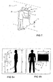
- FIG 7 shows a possibility for attaching an embodiment a cooking appliance 2 according to the invention on a Wall 22.
- two wall hooks 23 mounted in corresponding recesses (not shown) of the support plate 10 of the support element 8 of the cooking device 2 engage.
- the wall mounting is - as shown in FIG 7 - in a simple manner for a user 24 feasible, by hand without other tools or aids.
- the electrical connection via an electric cable 25 and a thereto attached plug 26, which in one with the plug 26th corresponding electrical wall socket 27 inserted becomes.
- FIG 7 The mounting option shown in FIG 7 for a Cooking appliance 2 according to the invention illustrates the mobility of the cooking appliance according to the invention 2. Without great effort it was taken from its current location, to one transported to another place and attached there. Further results from FIG 7, that for the ready attachment only two wall hooks and one electric Socket are required. These conditions are in Almost all rooms and often also outdoors or given can be created easily. The invention Cooking device 2 can thus be used almost everywhere in different rooms as well as outdoors or in one Caravans.
- FIG 8a and 8b show schematically an example of a ergonomically adapted to a user 24 attachment of a Embodiment of a cooking appliance 2 according to the invention on a wall 22 (not shown in FIG 8a / b).
- FIG. 8 a / b is a user standing on a floor 28 24 of the cooking device 2 to recognize.
- FIG. 8a / b the following are shown Dimensions indicated by double arrows: distance a between the floor 28 and the lower end 9 of the support element 8 of the cooking device 2, height h and width b of the cooking appliance 2 and size g of the user 24.
Landscapes
- Engineering & Computer Science (AREA)
- Chemical & Material Sciences (AREA)
- Combustion & Propulsion (AREA)
- Mechanical Engineering (AREA)
- General Engineering & Computer Science (AREA)
- Cookers (AREA)
- Baking, Grill, Roasting (AREA)
- Electric Ovens (AREA)
Applications Claiming Priority (2)
| Application Number | Priority Date | Filing Date | Title |
|---|---|---|---|
| DE10348713 | 2003-10-16 | ||
| DE10348713A DE10348713A1 (de) | 2003-10-16 | 2003-10-16 | Garofen |
Publications (2)
| Publication Number | Publication Date |
|---|---|
| EP1528327A2 true EP1528327A2 (fr) | 2005-05-04 |
| EP1528327A3 EP1528327A3 (fr) | 2011-11-02 |
Family
ID=34399538
Family Applications (1)
| Application Number | Title | Priority Date | Filing Date |
|---|---|---|---|
| EP04014793A Withdrawn EP1528327A3 (fr) | 2003-10-16 | 2004-06-24 | appareil cuisinier |
Country Status (2)
| Country | Link |
|---|---|
| EP (1) | EP1528327A3 (fr) |
| DE (1) | DE10348713A1 (fr) |
Cited By (13)
| Publication number | Priority date | Publication date | Assignee | Title |
|---|---|---|---|---|
| WO2008022685A1 (fr) | 2006-08-19 | 2008-02-28 | Electrolux Home Products Corporation N.V. | Appareil de cuisson, en particulier appareil de cuisson domestique |
| EP1927811A1 (fr) * | 2006-12-01 | 2008-06-04 | Niro-Plan Ag | Élément de cuisine équipée doté d'une hotte et d'une plaque de cuisson pivotante |
| WO2009157842A1 (fr) * | 2008-06-24 | 2009-12-30 | Aktiebolaget Electrolux | Appareil de cuisson |
| CN102472496A (zh) * | 2009-07-05 | 2012-05-23 | 易福德·纳文 | 可折叠式炉 |
| ITMI20120616A1 (it) * | 2012-04-16 | 2013-10-17 | Franke Technology & Trademark | Assieme cappa-piano di cottura, a scomparsa |
| CN104964324A (zh) * | 2015-07-07 | 2015-10-07 | 浙江机电职业技术学院 | 移动式集成灶 |
| EP3037734A1 (fr) * | 2014-12-19 | 2016-06-29 | Faber S.p.A. | Ensemble de cuisson portatif pourvu d'une hotte pliable |
| EP3070409A1 (fr) * | 2015-03-17 | 2016-09-21 | BSH Hausgeräte GmbH | Systeme de cuisson |
| CN106382661A (zh) * | 2016-10-24 | 2017-02-08 | 华帝股份有限公司 | 一种新型的厨房一体机 |
| CN108194947A (zh) * | 2018-03-20 | 2018-06-22 | 广东美的厨房电器制造有限公司 | 燃气灶具 |
| DE102017204238A1 (de) * | 2017-03-14 | 2018-09-20 | E.G.O. Elektro-Gerätebau GmbH | Kochvorrichtung mit einem Kochfeld und Anordnung einer Kochvorrichtung |
| US20220070979A1 (en) * | 2019-01-11 | 2022-03-03 | Fabita S.R.L. | Improved induction cooking system |
| CN118208753A (zh) * | 2024-05-21 | 2024-06-18 | 杭州老板电器股份有限公司 | 一种排放装置以及集成灶 |
Families Citing this family (1)
| Publication number | Priority date | Publication date | Assignee | Title |
|---|---|---|---|---|
| DE102006035251A1 (de) * | 2006-07-26 | 2008-01-31 | Vienco Gmbh | Verfahren und Anordnung zur Bestimmung der Garnqualität und/oder Spulenqualität eines laufenden Fadens auf Basis der Laser-Doppler-Anemometrie |
Family Cites Families (4)
| Publication number | Priority date | Publication date | Assignee | Title |
|---|---|---|---|---|
| FR2123750A5 (fr) * | 1971-01-29 | 1972-09-15 | Coste Caumartin Ets | |
| DE2414993A1 (de) * | 1974-03-28 | 1975-10-09 | Herbert Billian | Integrierte koch- und backstelle |
| FR2539846A1 (fr) * | 1983-01-24 | 1984-07-27 | Salvade Daniel | Cuisiniere |
| FR2618884B1 (fr) * | 1987-07-30 | 1989-11-24 | Invest Indl Immobilier | Dispositif de ventilation pour des systemes de cuisson du type a rechaud, table de cuisson encastrable ou cuisiniere |
-
2003
- 2003-10-16 DE DE10348713A patent/DE10348713A1/de not_active Withdrawn
-
2004
- 2004-06-24 EP EP04014793A patent/EP1528327A3/fr not_active Withdrawn
Cited By (22)
| Publication number | Priority date | Publication date | Assignee | Title |
|---|---|---|---|---|
| JP2010501972A (ja) * | 2006-08-19 | 2010-01-21 | エレクトロラクス ホーム プロダクツ コーポレーション エヌ ヴィ | 調理機器、特に家庭用調理機器 |
| AU2007287901B2 (en) * | 2006-08-19 | 2011-06-09 | Electrolux Home Products Corporation N.V. | Cooking appliance, in particular a household cooking appliance |
| WO2008022685A1 (fr) | 2006-08-19 | 2008-02-28 | Electrolux Home Products Corporation N.V. | Appareil de cuisson, en particulier appareil de cuisson domestique |
| CN101484756B (zh) * | 2006-08-19 | 2012-05-30 | 伊莱克斯家用产品股份有限公司 | 烹饪用具,尤其是家用烹饪用具 |
| EP1927811A1 (fr) * | 2006-12-01 | 2008-06-04 | Niro-Plan Ag | Élément de cuisine équipée doté d'une hotte et d'une plaque de cuisson pivotante |
| US8519310B2 (en) | 2008-06-24 | 2013-08-27 | Aktiebolaget Electrolux | Cooking appliance |
| WO2009157842A1 (fr) * | 2008-06-24 | 2009-12-30 | Aktiebolaget Electrolux | Appareil de cuisson |
| EP2318768A4 (fr) * | 2008-06-24 | 2017-06-07 | Aktiebolaget Electrolux | Appareil de cuisson |
| CN102472496A (zh) * | 2009-07-05 | 2012-05-23 | 易福德·纳文 | 可折叠式炉 |
| EP2452127A4 (fr) * | 2009-07-05 | 2013-01-02 | Yftach Navon | Réchaud pliant |
| ITMI20120616A1 (it) * | 2012-04-16 | 2013-10-17 | Franke Technology & Trademark | Assieme cappa-piano di cottura, a scomparsa |
| EP2653240A1 (fr) * | 2012-04-16 | 2013-10-23 | Franke Technology and Trademark Ltd | Ensemble hotte/plaque escamotable |
| EP3037734A1 (fr) * | 2014-12-19 | 2016-06-29 | Faber S.p.A. | Ensemble de cuisson portatif pourvu d'une hotte pliable |
| EP3070409A1 (fr) * | 2015-03-17 | 2016-09-21 | BSH Hausgeräte GmbH | Systeme de cuisson |
| CN104964324A (zh) * | 2015-07-07 | 2015-10-07 | 浙江机电职业技术学院 | 移动式集成灶 |
| CN104964324B (zh) * | 2015-07-07 | 2017-11-17 | 浙江机电职业技术学院 | 移动式集成灶 |
| CN106382661A (zh) * | 2016-10-24 | 2017-02-08 | 华帝股份有限公司 | 一种新型的厨房一体机 |
| DE102017204238A1 (de) * | 2017-03-14 | 2018-09-20 | E.G.O. Elektro-Gerätebau GmbH | Kochvorrichtung mit einem Kochfeld und Anordnung einer Kochvorrichtung |
| DE102017204238B4 (de) * | 2017-03-14 | 2021-05-06 | E.G.O. Elektro-Gerätebau GmbH | Kochvorrichtung mit einem Kochfeld und Anordnung einer Kochvorrichtung |
| CN108194947A (zh) * | 2018-03-20 | 2018-06-22 | 广东美的厨房电器制造有限公司 | 燃气灶具 |
| US20220070979A1 (en) * | 2019-01-11 | 2022-03-03 | Fabita S.R.L. | Improved induction cooking system |
| CN118208753A (zh) * | 2024-05-21 | 2024-06-18 | 杭州老板电器股份有限公司 | 一种排放装置以及集成灶 |
Also Published As
| Publication number | Publication date |
|---|---|
| EP1528327A3 (fr) | 2011-11-02 |
| DE10348713A1 (de) | 2005-05-12 |
Similar Documents
| Publication | Publication Date | Title |
|---|---|---|
| DE102006039087B4 (de) | Gargerät, insbesondere Haushalts-Gargerät | |
| DE3601460C2 (fr) | ||
| EP1528327A2 (fr) | appareil cuisinier | |
| EP2541154A1 (fr) | Hotte aspirante dotée d'un écran à vapeur guidé de manière coulissante | |
| DE102013014895A1 (de) | Küchenmöbel | |
| DE10309226A1 (de) | Kochvorrichtung | |
| DE102021105049A1 (de) | Einbaugargerät | |
| EP0650679B2 (fr) | Armoire de cuisine avec compartiment climatisé, notamment chauffé | |
| DE102012017121A1 (de) | Dunstabzugshaubensystem | |
| EP0034295A2 (fr) | Installation de cuisine encastrée | |
| DE10116098A1 (de) | Küchensystem | |
| DE202016104282U1 (de) | Downdraft-Abzugshaube mit reduziertem Raumbedarf | |
| EP3211325A1 (fr) | Filtre de table destine a aspirer les vapeurs de cuisine | |
| DE2753827A1 (de) | Tischgeraet zum garen mit hilfe von heissluft | |
| DE4305257C2 (de) | Küche | |
| EP2786674B1 (fr) | Meuble de cuisine avec plateau de travail déplaçable | |
| DE102020200077A1 (de) | Anordnung mit Arbeitsplatte und versenkbaren Kochfeld | |
| EP1254623B1 (fr) | Système de cuisson modulaire | |
| DE8905998U1 (de) | Gargerät | |
| DE102007018372B4 (de) | Ceranfeldabdeckung | |
| DE10000841A1 (de) | Dunstabzugsvorrichtung | |
| DE29722103U1 (de) | Kochfeldanordnung | |
| DE630354C (de) | Kocheinrichtung fuer Wohnkuechen u. dgl. | |
| DE202005000557U1 (de) | Gartenküche | |
| DE102014216165A1 (de) | Dunstabzugshaube mit Ablagefläche |
Legal Events
| Date | Code | Title | Description |
|---|---|---|---|
| PUAI | Public reference made under article 153(3) epc to a published international application that has entered the european phase |
Free format text: ORIGINAL CODE: 0009012 |
|
| AK | Designated contracting states |
Kind code of ref document: A2 Designated state(s): AT BE BG CH CY CZ DE DK EE ES FI FR GB GR HU IE IT LI LU MC NL PL PT RO SE SI SK TR |
|
| AX | Request for extension of the european patent |
Extension state: AL HR LT LV MK |
|
| RAP1 | Party data changed (applicant data changed or rights of an application transferred) |
Owner name: ELECTROLUX HOME PRODUCTS CORPORATION N.V. |
|
| RAP1 | Party data changed (applicant data changed or rights of an application transferred) |
Owner name: ELECTROLUX HOME PRODUCTS CORPORATION N.V. |
|
| RAP1 | Party data changed (applicant data changed or rights of an application transferred) |
Owner name: ELECTROLUX HOME PRODUCTS CORPORATION N.V. |
|
| PUAL | Search report despatched |
Free format text: ORIGINAL CODE: 0009013 |
|
| AK | Designated contracting states |
Kind code of ref document: A3 Designated state(s): AT BE BG CH CY CZ DE DK EE ES FI FR GB GR HU IE IT LI LU MC NL PL PT RO SE SI SK TR |
|
| AX | Request for extension of the european patent |
Extension state: AL HR LT LV MK |
|
| RIC1 | Information provided on ipc code assigned before grant |
Ipc: F24C 15/20 20060101ALI20110927BHEP Ipc: F24C 7/10 20060101AFI20110927BHEP |
|
| 17P | Request for examination filed |
Effective date: 20111010 |
|
| AKX | Designation fees paid |
Designated state(s): AT BE BG CH CY CZ DE DK EE ES FI FR GB GR HU IE IT LI LU MC NL PL PT RO SE SI SK TR |
|
| STAA | Information on the status of an ep patent application or granted ep patent |
Free format text: STATUS: THE APPLICATION IS DEEMED TO BE WITHDRAWN |
|
| 18D | Application deemed to be withdrawn |
Effective date: 20150106 |