EP1528334A2 - Embedded structure for installing an air-conditioning system to a wall - Google Patents
Embedded structure for installing an air-conditioning system to a wall Download PDFInfo
- Publication number
- EP1528334A2 EP1528334A2 EP04025109A EP04025109A EP1528334A2 EP 1528334 A2 EP1528334 A2 EP 1528334A2 EP 04025109 A EP04025109 A EP 04025109A EP 04025109 A EP04025109 A EP 04025109A EP 1528334 A2 EP1528334 A2 EP 1528334A2
- Authority
- EP
- European Patent Office
- Prior art keywords
- frame according
- wall
- boxlike
- tray
- container
- Prior art date
- Legal status (The legal status is an assumption and is not a legal conclusion. Google has not performed a legal analysis and makes no representation as to the accuracy of the status listed.)
- Withdrawn
Links
Images


Classifications
-
- F—MECHANICAL ENGINEERING; LIGHTING; HEATING; WEAPONS; BLASTING
- F24—HEATING; RANGES; VENTILATING
- F24F—AIR-CONDITIONING; AIR-HUMIDIFICATION; VENTILATION; USE OF AIR CURRENTS FOR SCREENING
- F24F13/00—Details common to, or for air-conditioning, air-humidification, ventilation or use of air currents for screening
- F24F13/22—Means for preventing condensation or evacuating condensate
- F24F13/222—Means for preventing condensation or evacuating condensate for evacuating condensate
-
- F—MECHANICAL ENGINEERING; LIGHTING; HEATING; WEAPONS; BLASTING
- F24—HEATING; RANGES; VENTILATING
- F24F—AIR-CONDITIONING; AIR-HUMIDIFICATION; VENTILATION; USE OF AIR CURRENTS FOR SCREENING
- F24F13/00—Details common to, or for air-conditioning, air-humidification, ventilation or use of air currents for screening
- F24F13/22—Means for preventing condensation or evacuating condensate
- F24F13/222—Means for preventing condensation or evacuating condensate for evacuating condensate
- F24F2013/227—Condensate pipe for drainage of condensate from the evaporator
Definitions
- the object of the present invention is an embedded frame for the wall mounting of conditioning systems or conditioners.
- the air conditioning systems are anchored to a support plate, or "template", which is in turn affixed to the wall by means of bolts, pressure nails or the like.
- a preparing (prearranging) box is wall-embedded behind the conditioner for the equipment power supply cables, conduits for the delivery of fluids used by the conditioner, condensate drain conduits, etc. to be passed therethrough and sorted out.
- This preparing box generally consists of a rectangular parallelepiped boxlike body that is embedded in the wall and closed by a removable protective lid, in order to allow access to the box for the arrangement and connection of the several conduits to the conditioner that is hanged to the wall by means of the template.
- the preparing box requires to be concealed from the user, mainly for visual appearance, and hence is covered by the conditioner.
- All-purposes preparing boxes of this type can be coupled, at the lower portion thereof, with a tray provided with a side drain port and having its longitudinal size equal to the preparing box size. This tray can be oriented in two directions such as to allow the drain port to be arranged at either one of the box side ends.
- the known all-purposes boxes force the operator to place the tray outlet port in proximity of only one of both conditioners.
- the object of the present invention is to provide an embedded frame of the all-purposes type, i.e. suitable for applications both with direct coupling for condensate outlet port, and with the possibility of applying a condensate collection tray, thereby overcoming the drawbacks of the all-purposes boxes conventionally used.
- the one according to the present invention allows for the coupling, in several distinct locations and orientations, with a lower container comprising at least one tray having a smaller longitudinal size than the box, thereby facilitating, as will be explained below, the mounting of the box in case of wall restraints.
- the all-purposes box of the present invention has a non-negligible advantage of providing, among the various possible embodiments of the coupling with a tray, the outlet port being in a substantially centred position relative to the vertical axis of the box.
- the lower container comprises at least two trays being aligned along the longitudinal axis and connected to each other via a junction element, which can be broken, if desired.
- a junction element which can be broken, if desired.
- Two distinct trays can be thus easily provided for one preparing box, or, by breaking the junction element, only one tray, the outlet port thereof can be placed and oriented according to various configurations along the lower wall of the preparing box.
- the all-purposes embedded frame consists of a body 1 having a substantially boxlike configuration developing along a longitudinal axis X (figures 1 and 2) and is open in the front to allow for the electric cables, or gas and water pipes to be inserted therein.
- this body 1 On the upper longitudinal 2 and lower coupling 3 walls of this body 1 there are provided some lips 4, and 4A being fixed at the pre-breaking lines 5, a preset number of these lips 4, 4A being removable by breaking the same, in order to obtain "windows" for the connecting pipes of the conditioner to be inserted therethrough and then subsequently applying a container 6A being provided with one or more condensate drain trays 6 (see figures 4, 5, 4A, 5A).
- the container 6A can be fastened, as required, to the lower wall 3 of the boxlike body 1, via removable fixing means 5A, 8, allowing the coupling of this container 6A in distinct locations and orientations along this wall 3.
- the single tray 6, consisting of an elongated concave body 7 (figures 4A and 5A) with a substantially U-shaped section (figure 6), can be snap fixed to the body 1 of the box, by means of elastic hooks 8 being integral with the edges of tray 6 and suitable to engage within corresponding seats 5A, being provided along the lower wall 3 of the body 1.
- the tray 6 is equipped with a condensate outlet port 15 being preferably arranged at a side end thereof, and according to an advantageous aspect, having two or more diameters in order to be connected to pipes having different diameters.
- the lower wall of the drain tray 6 can be biased in a sloping manner towards the outlet port 15, according to known techniques, in order to facilitate condensate drainage.
- the longitudinal linear development of tray 6 is less than the length (as considered on the X axis of figures 1-3) of the coupling wall 3, and preferably less than or equal to half the length thereof.
- the tray 6 can be coupled to the box 1, such as partially shown in figure 8, according to different positions and orientations, with the outlet port 15 coming either on the right, on the left, or in the center, thereby allowing a high installation flexibility.
- the tray 6 can be indeed shifted relative to the box 1 and coupled therewith in a location where it does not interfere with such obstacles.
- two trays 6 can be aligned along the longitudinal axis thereof and be connected to each other via a junction element, or partition wall, 16, such as shown in figures 4 and 5, such as to form the above container 6A.
- the container 6A In the event that the trays 6 have side outlet ports 15, the container 6A, the longitudinal extension thereof being preferably equal to the length of coupling wall 3 of the boxlike body 1, will be thus provided with outlets 15 that, after the container 6A has been mounted on the wall 3 of the boxlike body 1, will be arranged at the side ends of the latter.
- the partition wall 16 can advantageously have two prebreaking lines at each one of the trays 6, such that the container 6A, when required by the installation conditions, can be divided in the two trays 6.
- the box 1 of figures 1 and 3 can be either provided with one single condensate drain 6 that, as described above, can be variously positioned and oriented along the coupling wall 3 of the boxlike body 1, or with two drain trays 6.
- the use of the container 6A with the two trays 6 being fastened by the partition wall 16 is particularly advantageous when one desires to mount two conditioners in a series using the same box 1 for each.
- the box from figures 1 to 3 is provided with an almost planar lower wall 3, for an optional condensate drain pump to be housed therein.
- the conditioner is affixed to the wall 14, the box 1 being previously embedded therein, for the arms 9 of the corresponding support plate (not illustrated) to be engaged thereon.
- the box 1 is provided on the front side thereof with a plurality of flanges 10, whether previously drilled or not, which are slidingly mounted along guide ribs 11 provided on the edge 12 of the front opening of the box 1 (figures 1 and 6). These flanges are positioned at the arms 9 of figure 6, and offer the opportunity of anchoring the support template for the conditioner with screws 13 or the like.
Landscapes
- Engineering & Computer Science (AREA)
- Chemical & Material Sciences (AREA)
- Combustion & Propulsion (AREA)
- Mechanical Engineering (AREA)
- General Engineering & Computer Science (AREA)
- Air Filters, Heat-Exchange Apparatuses, And Housings Of Air-Conditioning Units (AREA)
- Devices For Blowing Cold Air, Devices For Blowing Warm Air, And Means For Preventing Water Condensation In Air Conditioning Units (AREA)
- Cultivation Receptacles Or Flower-Pots, Or Pots For Seedlings (AREA)
Abstract
Description
- Figures 1 to 3 shows front, top and bottom views of the inventive box without tray, respectively;
- Figure 1A shows the closing lid of the box;
- Figures 4 and 5 show top and bottom views of a twin tray to be used with the box of the above figures, respectively;
- Figures 4A and 5A show top and bottom views of a single tray to be used with the box of the preceding figures, respectively;
- Figure 6 shows a cross-section of the inventive box as being mounted on an air conditioning system;
- Figure 7 shows the side sectional view of the box; and
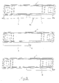
- Figure 8 shows three possible mounting configurations of the box
Claims (12)
- An embedded frame for the wall mounting of conditioning systems of the type comprising a boxlike body (1) being provided with at least one coupling wall (3) with a lower container (6A) for condensate drainage, said lower container (6A) comprising at least one tray (6) having a condensate outlet port (15), characterized in that said tray (6) has a lower length than the length of said coupling wall (3) and said structure (1) also comprises means (5A, 8) for removably fixing said container (6A) in different positions and orientations along said coupling wall (3).
- The frame according to claim 1, characterized in that the length of said tray (6) is less than or equal to half the length of said coupling wall (3) of the boxlike body (1).
- The frame according to claim 1 or 2, characterized in that said container (6A) comprises at least two trays (6).
- The frame according to claim 3, characterized in that said two trays (6) are aligned along the longitudinal axis thereof and are connected to each other by a junction element (16).
- The frame according to claim 3 or claim 4, characterized in that each of said two trays (6) comprises an outlet port (15), said outlet ports being provided at the opposite longitudinal ends of the container (6A).
- The frame according to any claim 3 to 5, characterized in that each of said two trays (6) comprises an outlet port (15) and has a lower wall being biased in sloping manner towards said outlet port (15).
- The frame according to any claim 3 to 6, characterized in that said junction (16) can be broken in order to obtain the separation of said two trays (6).
- The frame according to any preceding claim, characterized in that said fixing means comprise a plurality of grip hooks (8) being integral with the container (6A) and corresponding seats (5A) being formed in the boxlike body (1) at and/or in proximity of said coupling wall (3).
- The embedded boxlike frame according to the preceding claims, characterized in that the coupling of said body with each tray (6) is provided by means of a plurality of removable lips (4A) and slots (5A) being provided on the lower wall (3) of said boxlike body (1).
- The embedded boxlike frame according to the preceding claims, characterized in that said lips (4, 4A) are fixed at pre-breaking lines provided on the upper longitudinal wall, on the lower longitudinal wall, and side walls of said boxlike body (1).
- The embedded boxlike frame according to the preceding claims, characterized by having one or more flanges or plates (10) being slidingly mounted on a guide rib (11) provided along the edge (12) of the front opening of said body (1).
- The embedded boxlike frame according to the preceding claims, characterized in that said flanges or plates (10) are drilled.
Applications Claiming Priority (2)
| Application Number | Priority Date | Filing Date | Title |
|---|---|---|---|
| ITMI20030501 ITMI20030501U1 (en) | 2003-10-28 | 2003-10-28 | BUILT-IN STRUCTURE FOR WALL INSTALLATION OF CONDITIONING PLANTS |
| ITMI20030501 | 2003-10-28 |
Publications (2)
| Publication Number | Publication Date |
|---|---|
| EP1528334A2 true EP1528334A2 (en) | 2005-05-04 |
| EP1528334A3 EP1528334A3 (en) | 2007-04-25 |
Family
ID=30131046
Family Applications (1)
| Application Number | Title | Priority Date | Filing Date |
|---|---|---|---|
| EP04025109A Withdrawn EP1528334A3 (en) | 2003-10-28 | 2004-10-22 | Embedded structure for installing an air-conditioning system to a wall |
Country Status (2)
| Country | Link |
|---|---|
| EP (1) | EP1528334A3 (en) |
| IT (1) | ITMI20030501U1 (en) |
Cited By (1)
| Publication number | Priority date | Publication date | Assignee | Title |
|---|---|---|---|---|
| US20180202685A1 (en) * | 2017-01-18 | 2018-07-19 | Nicola Pignolo | Built-in box for supplying internal units of air conditioning systems provided with a condensate collection tray |
Family Cites Families (3)
| Publication number | Priority date | Publication date | Assignee | Title |
|---|---|---|---|---|
| US611536A (en) * | 1898-09-27 | Rotary engine | ||
| IT242870Y1 (en) * | 1997-07-31 | 2002-02-04 | Nicola Pignolo | BUILT-IN BOX FOR THE SUPPLY OF THE INDOOR UNITS OF THE AIR CONDITIONING SYSTEMS, PROVIDED WITH A COLLECTION-CONDENSATE CHANNEL |
| IT1311815B1 (en) * | 1999-01-28 | 2002-03-19 | Tecnosystemi Srl | BUILT-IN CONTAINER STRUCTURE, IN PARTICULAR FOR THE ARRANGEMENT OF AIR CONDITIONING SYSTEMS. |
-
2003
- 2003-10-28 IT ITMI20030501 patent/ITMI20030501U1/en unknown
-
2004
- 2004-10-22 EP EP04025109A patent/EP1528334A3/en not_active Withdrawn
Cited By (1)
| Publication number | Priority date | Publication date | Assignee | Title |
|---|---|---|---|---|
| US20180202685A1 (en) * | 2017-01-18 | 2018-07-19 | Nicola Pignolo | Built-in box for supplying internal units of air conditioning systems provided with a condensate collection tray |
Also Published As
| Publication number | Publication date |
|---|---|
| ITMI20030501V0 (en) | 2003-10-28 |
| ITMI20030501U1 (en) | 2005-04-29 |
| EP1528334A3 (en) | 2007-04-25 |
Similar Documents
| Publication | Publication Date | Title |
|---|---|---|
| US5685113A (en) | Lay-in wireways for a space divider system | |
| US5486650A (en) | Partition for dividing a device box | |
| US5913787A (en) | Communications conduit connector mounting device | |
| KR100355010B1 (en) | Box for the Feeding of the Inner Units of Air-conditioning Systems | |
| US20090090073A1 (en) | Cable management system for a raised floor grid system | |
| US7825336B2 (en) | Electrical outlet box having high and low voltage compartments | |
| US20060285812A1 (en) | Cable trough cover | |
| US3996959A (en) | Washer-connector service box | |
| GB2289903A (en) | Conduit connecting mechanism for a screen panel | |
| CA2639087C (en) | Cable junction box with provision for service loops | |
| CA2689180A1 (en) | Cable and box support plate | |
| US7446266B1 (en) | Reconfigurable conduit body assembly for non-metallic conduit | |
| US4973797A (en) | Gasketless weatherproof housing | |
| US20060231278A1 (en) | Expandable structured wiring box | |
| JPH0748888A (en) | Power panel body | |
| US9841209B2 (en) | Evaporator rough-in box | |
| US7126058B2 (en) | Adaptable low voltage electrical box | |
| AU774788B2 (en) | Trunking port accessory | |
| US4974421A (en) | Plastic pan assembly having an U-shaped supporting bracket for use in air conditioners and refrigerators | |
| EP1528334A2 (en) | Embedded structure for installing an air-conditioning system to a wall | |
| US20020185293A1 (en) | Communications distribution box having improved access | |
| CN101868894B (en) | Flexible cover for cable trough system | |
| KR100354485B1 (en) | Distributing duct having external connection grooves | |
| EP0035516B1 (en) | Wall for partitioning into sections a channel for electrical cables | |
| US6362430B1 (en) | Integrated cable management and equipment mounting device |
Legal Events
| Date | Code | Title | Description |
|---|---|---|---|
| PUAI | Public reference made under article 153(3) epc to a published international application that has entered the european phase |
Free format text: ORIGINAL CODE: 0009012 |
|
| AK | Designated contracting states |
Kind code of ref document: A2 Designated state(s): AT BE BG CH CY CZ DE DK EE ES FI FR GB GR HU IE IT LI LU MC NL PL PT RO SE SI SK TR |
|
| AX | Request for extension of the european patent |
Extension state: AL HR LT LV MK |
|
| PUAL | Search report despatched |
Free format text: ORIGINAL CODE: 0009013 |
|
| AK | Designated contracting states |
Kind code of ref document: A3 Designated state(s): AT BE BG CH CY CZ DE DK EE ES FI FR GB GR HU IE IT LI LU MC NL PL PT RO SE SI SK TR |
|
| AX | Request for extension of the european patent |
Extension state: AL HR LT LV MK |
|
| 17P | Request for examination filed |
Effective date: 20071019 |
|
| AKX | Designation fees paid |
Designated state(s): AT BE BG CH CY CZ DE DK EE ES FI FR GB GR HU IE IT LI LU MC NL PL PT RO SE SI SK TR |
|
| 17Q | First examination report despatched |
Effective date: 20081219 |
|
| GRAP | Despatch of communication of intention to grant a patent |
Free format text: ORIGINAL CODE: EPIDOSNIGR1 |
|
| INTG | Intention to grant announced |
Effective date: 20150310 |
|
| STAA | Information on the status of an ep patent application or granted ep patent |
Free format text: STATUS: THE APPLICATION IS DEEMED TO BE WITHDRAWN |
|
| 18D | Application deemed to be withdrawn |
Effective date: 20150721 |